1st row area
sensitivity potentiometer
2nd & 3rd row area
sensitivity potentiometer
Check the wiring cable.
Check the connector.
Replace as necessary.
Check the
dipswitch settings
.
Set 1st row area angle at -5 degrees
(shallow) or 2nd & 3rd row area angle
at +5 degrees (deep).
Set dipswitch 6 on left bank dipswitch of
OA-613 on/up (shallow).
Remove the objects.
Verify proper settings.
See installation manual section 4.
Adjust the sensitivity lower.
Adjust the sensitivity higher.
Set the snow mode to “Snow”.
Set the rain mode to “Rain”.
Use the rain-cover (Separately available).
Or install in a place keeping the
water drops off.
Check the installation condition referring
to MANUFACTURER'S STATEMENT.
Remove the objects.
Verify proper settings.
See installation manual section 4.
Verify proper settings.
See installation manual section 4.
Possible countermeasures
Set to the stated voltage.
Wrong wiring cable (Brown &Orange wires)
of OC-913C.
Connection failure from OA-613 to
OC-913C.
Twice
Orange
blinking
Defective communication cable.
Blinking
Yellow
Blinking
Green
OC-913C dipswitches set wrong.
Solid
Green
or
Solid
Red
or
Blinking
Red
Proper
Improper 1st row or 2nd & 3rd row area
angle adjustment.
Stalling caused by traffic just outside of
swing path.
Moving objects near guide rails.
Area width dipswitches set wrong.
(Right bank dipswitches on OA-613)
Sensitivity is too high.
Sensitivity is too low.
Snow drifting.
Other than above.
Water drops on the detection window.
Wet floor.
The exhaust emission or fog penetrate
into the detection area.
Reflecting objects in the detection area.
Objects that move or emit light
(Ex.Plant, illumination, etc.)
Red or
Blinking
Red
Area width dipswitches set wrong.
(Right bank dipswitches on OA-613)
Slow
Green
blinking
Proper
Signal saturation
.
Sensor failure.
Fast
Green
blinking
Proper
Slow
Orange
blinking
When all the area are inactive.
(Right bank dipswitches on OA-613)
Solid
Green Proper
Twice
Orange
blinking
or
None
Proper
Solid
Green
Proper
Symptom
OA-613
None
Operation indicator
OC-913C
Initial setup
can not start.
Incomplete
initial setup
Door operates
when no one
is in the
detection area.
(Ghosting)
OA-613 detects
but door operate.
Door remains
open.
Door does not
operate properly
when a person
enters the
detection area.
(Sensor does
not detect.)
Possible cause
Power supply voltage.None
OC-913C dipswitches set wrong.
Check the
dipswitch settings
.
See installation manual section 2.
Remove highly reflecting objects from the
detection area. Or lower the sensitivity.
Set 1st row area angle at -5 degrees
(shallow) or 2nd & 3rd row area angle
at +5 degrees (deep).
Improper 1st row or 2nd & 3rd row area
angle adjustment.
Wipe the detection window with a damp
cloth. (Do not use any cleaner or solvent.)
Dirty detection window.
Contact your installer or service engineer.
Improper wiring of door equipment on / off /
hold switch.
Verify proper wiring of on / off /
hold switch.
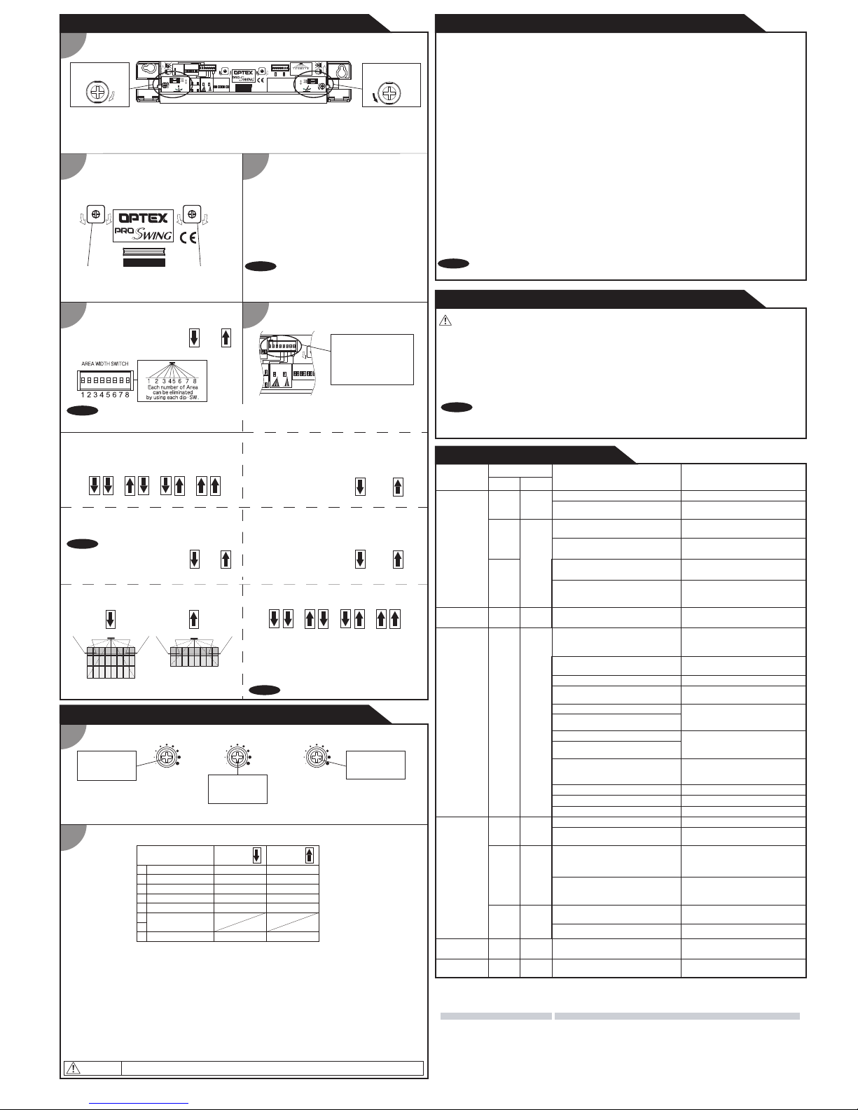
2Setting the dipswitches
1Area depth angle adjustment
5Mode setting switch
(left bank)
4Area width setting switch
(right bank)
5-1.Setting the presence timer
2
ADJUSTMENTS for OA-613
Adjusting the sensitivity
1. Always keep the detection window clean. If dirty, wipe the window with a damp cloth.(Do not use any cleaner / solvent.)
2. Do not wash the sensor with water.
3. Do not disassemble, rebuild or repair the sensor yourself, otherwise electric shock may occur.
4. When the operation indicator blinks Green, contact your installer or service engineer.
5. Always contact your installer or service engineer when changing the settings.
6. Do not paint the detection window.
WARNING
1. After applying power, wait 10 seconds then walk test detection area to ensure proper operation.
2. Do not place any objects that move or emit light in the detection area. (e.g. Plant, illumination, etc.)
NOTE
INFORM BUILDING OWNER / OPERATOR OF THE FOLLOWING ITEMS
1 2 1 2 1 2 1 2
15 Sec. 30 Sec. 60 Sec. 120 Sec.
33
Setting2Setting1
To comply with ANSI standard, set to "30sec." or longer.
1st row area
angle screw
2nd &3rd row area
angle screw
Set the dipswitch as necessary.
Active
Inactive
1,2
3
4
5
6
7,8
: Presence timer
: Frequency
: Rain mode
: Snow mode
: Area depth
: Extend Lockout timer
1Timer adjustment
ADJUSTMENTS for OC-913C
3Initial setup
This sensor has the function to fit floor condition changes
automatically.
Therefore, even if objects are put in the detection area,
sensor will learn the changes gradually and set back to
normal operations automatically after presence timer has
expired.
To enable a Learn process only, flip any dipswitch
on OA-613 sensor head and wait 1 second, then flip it
back to the original position.
NOTE
See PREMIER Mk2 installation manual section 6
(Premier Learn process).
InactiveActive
5-2.Setting the frequency
When using more than two sensors close to each other,
set the different frequency for each sensor by dipswitch 3.
44
RainNormal
5-3.Setting the rain mode
Set dipswitch 4 to "Rain" if the sensor is used in a
region with a lot of rain.
55
SnowNormal
5-4.Setting the snow mode
Set dipswitch 5 to "Snow" if the sensor is used in a
region with snow or a lot of insects.
66
SHALLOWDEEP
5-5.Setting the area depth 5-6.Setting the Extend Lockout timer
NOTE
Safety output
hold time
(0.5 to 10sec.)
Lockout
timer
(0 to 24sec.)
MaxMinMaxMin
Set the dipswitches as shown below.
OPTEX Co.,LTD.
Manufacturer
5-8-12 Ogoto Otsu 520-0101, Japan
TEL.: +81(0)77 579 8700
FAX.: +81(0)77 579 7030
WEBSITE: www.optex.co.jp
East Coast Office
8510 McAlpines Park Drive, Suite 108
Charlotte, NC 28211 U.S.A.
TOLL-FREE: 800 877 6656
FAX.: +1 704 365 0818
WEBSITE: www.optextechnologies.com
OPTEX Technologies Inc.
Corporate Headquarters
North and South American Subsidiary
3882 Del Amo Blvd., Suite 604
Torrance, CA 90503 U.S.A.
TOLL-FREE: 800 877 6656
FAX.: +1 310 214 8655
WEBSITE: www.optextechnologies.com
TROUBLESHOOTING
NOTE
When set to "Rain", the actual
detection area may become
smaller.
NOTE Whenever a Dipswitch is moved a Premier Learn process is enabled, ensure proper completion of
process (See step 3).
7 8 7 8 7 8 7 8
+0 Sec. +1Sec. +2 Sec. -1 Sec.
Fine-tune the lockout time after setting the lockout timer
on OC-913C by volume (0-24 sec.)
Only effective when Dipswitch 3 is set to “Manual” and
Dipswitch 5 is set to “OFF” on OC-913C.
MaxMin
Knowing act
timer
(0 to 24sec.)
Knowing Act Function
1. Safety Relay Contact
2. Door Open Signal Switch
3. Auto Lock out
4. Knowing Act
5. Data Input
6,7. Future Development (not used)
8. Stand Alone
Set the lockout time to the time for the door
to reach full closed position
from full open position. Lockout timer is
effective only when dipswitch 3 is set
to “Manual” and dipswitch 5 is set to “OFF”.
Set the time required for door to close from fully open position to
within 10 degrees when uses for Knowing Act application(dipswitch 4:ON).
See ADJUSTMENTS for OC-913C
NOTE
Set the safety output duration time.
5733580
OA-613
Green
Red Blink
Red
YellowBlink
: Stand-by
:
1st Row Area
Det.
: 2
nd㸤UGRow Area
Det.
: Learning
OPERATION INDICATOR
SHALLOWDEEP
AREA DEPTH
6 6
CONNECTOR
1st row area depth Adjustment
DEEP
SHALLOW
SHALLOW
DEEP SHALLOW
PATTERN
DEEP
PATTERN
OPERATION INDICATOR
Min Max Min Max
Active Inactive
AREA WIDTH SWITCH
2nd㸤UGrow areadepth Adjustment
DEEP
SHALLOW
DEEP
PATTERN
SHALLOW
PATTERN
DEEP
SHALLOW
CONNECTOR
Each numberofArea
canbeeliminated
byusingeachdip-SW.
1st row area
sensitivity
potentiometer
2nd 㸤UG row
area sensitivity
potentiometer
EXTEND
LOCKOUTTIMER(Sec.)
+0 +1 +2 -1
7 8 7 8 7 8 7 8
SNOW MODE
612:1250$/
55
RAINMODE
5$,11250$/
44
FREQUENCY
SWITCH
6(77,1*
3
6(77,1*
3
PRESENCE
TIMER(Sec.)
1 2
1 2
1 2
1 2
OA-613
OPERATION INDICATOR
Min Max Min Max
1st row area
sensitivity
potentiometer
2nd 㸤UG row
area sensitivity
potentiometer
Start with 2nd & 3rd row area depth angle
at +5 degrees(deep).
If after walk test the pattern is too deep,
adjust towards shallow as necessary.
For standard
application.
For bi-fold or
smaller door.
OC-913C Dip-SW 8 is ON,
but OA-613 is also connected to OC-913C.
: Enable area
: Disable area
Use this function when Primary Activation is knowing act (i.e. Push Plate, Card reader, etc.) and
a secondary activation sensor(door mount or header mount) is desired.
See WIRING in the installation manual when Knowing Act Function is required.
Secondary activation sensor status in Knowing Act Function:
- Full Closed position
Secondary activation sensor is inactive until the knowing act device is initiated.
Door can be used manually without activation or reactivation from sensor.
- Door Opening & Full Open
When door is activated by Knowing Act, the secondary activation sensor is active
and the door will remain open when the sensor is in detection.
- Door closing
Secondary activation sensor is active and will reactivate the door upon detection
until the Knowing Act timer expires. Set the Knowing Act timer on OC-913C control
to stay active to within 10 degrees from full closed.
When using the Knowing Act Function, Push/Pull activation MUST be disabled at the door control.
Safety Relay Contact
Door Open Signal Switch
Auto Lock Out
Knowing Act ON
Manual
OFF
Auto
1
2
3
4
5
6
7
8
Dipswitch setting ONOFF
Data Input
Future Development
Stand Alone OFF
OFF
ON
ON
Act
NO NC
Saf
: Choose the Relay Contact.
: Determines safety output when door is open.
: Set the lockout method
ON : Manual (by volume setting on OC-913C)
OFF : Auto (by motor voltage)
: If uses KnowingAct Function, set to “ON”.
: If using data output from door control for Lockout, set to “ON”.
When Data Input is “ON”, setting of Auto Lock Out(dipswitch 3) is ignored.
: Set to “ON” when door mount sensor and OC-913C are used
for Knowing Act application without OA-613.
If use OA-613, set OC-913C Dip-SW 8
to “OFF”.
If do not use OA-613, disconnect it.
When using OA-613, dipswitch 8 must be set to “OFF”.
Start with 1st row area depth angle
at -5 degrees(shallow).
If after walk test the pattern is too shallow,
adjust towards deep as necessary.
CAUTION