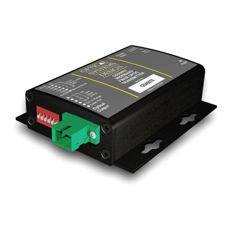
Optical Systems Design OSD8810 User manual

Doc. ID 10108405
OPERATOR MANUAL
OSD8810
Digital Single Channel Micro
Video Transmitter
The OSD8810 fiber optic video transmitter is designed to
provide wideband CCTV quality video over up to 3km of
multimode optical fiber or at least 30km of singlemode
fiber with 100km optionally possible. Its major feature
compared to other digital transmitters is its small size, just
25mm x 40mm elliptical diameter x 38mm long. It also fits
directly onto the BNC connector of the camera. It
operates with the OSD8815, OSD8865 digital video
receivers.
Specifications and Features
▲
Surveillance links up to over 100km
▲
Industrial process monitoring
▲
Safe city CCTV system video transmission
▲
Broadcast links
▲
Extends wideband video transmission to over
3km of multimode fiber and at least 30km of
singlemode fiber with 100km optionally possible
▲
Performance is maintained at the same quality
over all link lengths
▲
Fits directly onto the camera
▲
Eliminates length dependant adjustments often
required with coax or Cat 5 based systems
▲
More secure than coaxial or Cat 5 cables
▲
Broadcast quality true 10 bit video with 10MHz
bandwidth
▲
Operates with the OSD8815R and OSD8865
digital receivers
▲
Two audio channels are optionally available
Typical Configurations
Mounting Details
The OSD8810 can be mounted directly on the back of a
camera to the female BNC connector. Below is an outer
case drawing showing the dimensions.
Power Connection
The OSD8810 requires external DC or AC power. The
acceptable DC voltage range is +9 to +35V
DC
, and the
allowed AC voltage range is 22 to 28V
AC
, @ 1.5VA. Power
should be connected to the 3.5mm 2-way terminal block
located at the side of the case. Take care to connect DC
power with the correct polarity as shown below. A 3.5mm 2-
way terminal plug is supplied with the OSD8810.
Signal Connection
Video input signal should be connected to the male BNC
connector on the OSD8810 directly from the camera.
The optical fiber cable must be terminated with the
appropriate ST type optical connector. Before
connection, inspect the ends of the connectors to ensure
that no dust or dirt is present as it could contaminate the
modem connector and result in poor performance.
If it is necessary to clean the cable connectors use
isopropyl alcohol and lint free tissue to remove
contamination.
LED INDICATORS
Indicator Colour Function
Video Present Blue Video signal connected
Off No video signal present
Laser OK
Green Laser in normal operation
Red Laser Fail/No optical output
Video
Input
Video
Output
Optical
Fiber Link
OSD8810
OSD8815R
OSD8810
OSD8810
OSD8810
OSD8865
Optical
Fiber Link
Video
Inputs
Video
Outputs
Rear of camera
Power
ST Fiber cable
OSD8810
38 25
40
17.2
12.8
0V
+ve
LED Indicators
Optical Output
Video Present
Laser OK

Doc. ID 10108405
Optional Audio Version Connections
Technical Specifications
Specification Performance
Input Impedance 75Ω
Input Level 1Vp-p nominal
Video Connector BNC Plug
Power Connector 3.5mm 2-way terminal block
Bandwidth 5Hz to 10MHz +1/-3dB
Weighted Signal to
Noise Ratio
>65dB when operating with the
OSD8815R or OSD8865
Diff Gain/Phase <0.7%, <0.7˚
Audio BW 15Hz to 20KHz +1, -3dB
Audio Input
Impedance >10KΩ/200Ω
Audio Input Level 200mVrms
Audio Headroom 15dB
Audio Weighted SNR
>90dB at maximum level
Audio Distortion <0.02%
Audio Connector 3.5mm Stereo Socket
Transmitter
Wavelength 1310nm ± 40nm
Transmitter Coupled
Power
-15 to -10dBm into singlemode fiber
-10 to -5dBm into multimode fiber
Optical Connectors ST
Power Requirements +9 to +35V
DC
22 to 28V
AC
@ 1.5VA
Enclosure Elliptical Extrusion
Dimensions (mm) 25 x 40 x 38L (excluding connectors)
Weight of Module 50g
Operating
Temperature -40 to 75°C
Relative Humidity 0 to 95% non-condensing
102881005
▲
ELECTROMAGNETIC COMPATIBILITY
WARNING: This is a Class A product. In a domestic
environment this product may cause radio interference
in which case the user may be required to take
adequate measures.
▲
OPTICAL OUTPUT OPERATION
WARNING: Laser Safety: Class 1 Laser Product per
IEC/EN 60825-1:20011 standard.
Class 1
The OSD8810 is a Class 1 laser product.
Precautions
▲
All service personnel should be provided training
as to the hazards of direct viewing of laser
radiation and of the precautionary measures
during servicing of equipment
▲
Areas where laser products are installed should
be restricted in access to trained service
personnel only and appropriate warning signs
posted in the work area.
▲
All laser apertures should be covered by
protective covers when not connected to optical
fibers. Never leave outputs uncovered.
▲
Laser equipment should be positioned above or
below eye level where possible. Apertures should
be positioned away from personnel.
▲
Protective eyewear should be worn in the vicinity
of laser equipment
Maintenance
This equipment has been fully tested prior to dispatch and
is ready for immediate operation. However it is advisable to
check for external transportation damage before operation.
If damage is evident, return the unit with the packaging to
your supplier immediately.
Visually check for the following:
▲
Check that the correct power source is
connected to the power socket.
▲
Check that the video signal is connected to the
modem correctly and that the distant modem
has been terminated correctly to any external
equipment.
▲
Inspect the optical connector for any
contamination and clean using isopropyl
alcohol and a lint free tissue if any
contamination is detected.
▲
Check that any external terminations are
connected if the system configuration
requires them.
Warranty/Repairs
Thank you for purchasing equipment designed, manufactured
and serviced by Optical Systems Design (OSD). OSD warrants
that at the time of shipment, its products are free from defects
in material and workmanship and conforms to specifications.
For warranty period and repair service please call your local
OSD distributor.
Optical Systems Design reserves the right to repair or replace
faulty modules/units. Should your unit be faulty, please obtain a
“Return Material Authorisation” (RMA) form and number before
returning goods.
Goods must be returned in adequate packing material to
Optical Systems Design, Warriewood or its nominated
authorised representative, for all repairs.
This warranty does not apply to defects caused by
unauthorized modifications, misuse, abuse or transport
damage to the equipment. All modifications to OSD’s standard
product will need written authorization and will be charged at
normal repair rates. All modifications are to be carried out by
OSD Technicians. Warranty is void if unauthorized removal
and/or tampering with serial number and/or repair labels is
evident.
OPTICAL SYSTEMS DESIGN PTY LTD
7/1 Vuko Place, Warriewood 2102.
PO Box 891, Mona Vale,
NSW, Australia 1660.
Phone: +61 2 9913 8540
Fax: +61 2 9913 8735
Audio Input
Ch1
Left
Ch2
Right
Gnd
3.5mm Stereo Plug
Other Optical Systems Design Transmitter manuals
Popular Transmitter manuals by other brands

Applied Wireless
Applied Wireless PAR900M user guide

JAROLIFT
JAROLIFT TDRC08W Original assembly and operating instructions

Elinchrom
Elinchrom El-Skyport user manual

SMAR
SMAR LD291 Operation and maintenance instruction manual

DTC
DTC Palladium II Digital manual

Audio Technica
Audio Technica ATW-T6002 S user manual