OPTICLIMATE PRO 3 User manual

OPTICLIMATE
PRO 3 & PRO4 SPLIT (INVERTER)
INSTALLATION AND USER GUIDE
EN
All manuals at:
www.theclimatefactory.com
For any inquiry:
info@theclimatefactory.com
OPTIMAL CLIMATE CONTROL

THE CLIMATE FACTORY/USER MANUALS/OPTICLIMATE SPLIT (INVERTER)
www.theclimatefactory.com info@theclimatefactory.com
© The Climate Factory
INSTALLATION
If the unit is placed in a narrow room or in the ridge of a gable roof, the fan outlet side can be installed at the
short side of the unit.
This can be done simply by reversing the dark panels. The fan panel is moved around to the short side of the
unit. Loosening the corner bracket will eliminate the need for disconnecting cable connections.
It is important, however, to release the outlet air to the fan.
Fan installation (front / side)
Installation
To guarantee proper air suction, leave at least 15cm of space between the wall and the backside of the unit,
where the carbon & dust lters and air inlet are located. At least 15cm of space should also be left between the
topside of the unit and the ceiling. Larger spaces are preferred. The unit must stand free from the wall to avoid
contact noises.

THE CLIMATE FACTORY/USER MANUALS/OPTICLIMATE SPLIT (INVERTER)
www.theclimatefactory.com info@theclimatefactory.com
© The Climate Factory
1 cm mas fall
INSTALLATION
The unit should be mounted in such a way that the side of the condensation drain is at least 1 cm lower than
the other side (slope) to ensure that the condensate drains properly. In practice, the 1 cm elevations at all
corners – except the corner of the condensate drains – are exactly right for a correct fall. Using a spirit level is
recommended.
To avoid contact noises, the OptiClimate is delivered with rubber shock absorbers as standard issue, that are
suitable for suspended installation. If the OptiClimate is going to be placed on a solid base, the rubber shock
absorbers supplied with the connection set need to be used.
Special insulating springs can also be supplied for areas that have to be extra quiet. Placing the insulating
springs on the supports will ensure that the unit has automatic fall to the condensation drain.
The rubber feet with which the OptiClimate is placed on the pallet are use to suspend the unit by means of
thread ends.
A thread end, a large washer and a nut must be tted. (not supplied)
Installation of rubbers Installation of insulating springs

THE CLIMATE FACTORY/USER MANUALS/OPTICLIMATE SPLIT (INVERTER)
www.theclimatefactory.com info@theclimatefactory.com
© The Climate Factory
First, the panel at the left side near the manometer should be removed to make the various electrical connec-
tions.
A ve-core cable, automatic moisture meter, remote control and temperature sensor are supplied with the unit.
Their cables can be led to the outside through the opening at the bottom of the panel. The power cable for the
power supply can be led through the black feed-through rubber at the side of the unit.
Automatic moisture meter,
remote Control, power supply
for clock, temperature sensor,
ve-core cable
ELECTRICAL CONNECTIONS
Power cord

THE CLIMATE FACTORY/USER MANUALS/OPTICLIMATE SPLIT (INVERTER)
www.theclimatefactory.com info@theclimatefactory.com
© The Climate Factory
ELECTRICAL CONNECTION
Room Temperature
Sensor A101
Alarm
port
Alarm port
The printed circuit-board has an alarm port, which is activated (makes contact) in case of a malfunction (error).
This contact can be connected to a GSM detector. The contact can be set to NO (contact open) or NC (con-
tact closed) using the Settings menu. This means that the contact will be opened or closed in case of detection.
See the manual of the GSM detector or alarm for this.
Automatic moisture meter with light cell
The automatic moisture meter with built-in light cell supplied with the unit is already connected. The cable should
be led through the opening in the panel. The automatic moisture meter should be hung in the room and may
NOT be covered.
The light cell in the automatic moisture meter automatically switches the OptiClimate from day to night mode.
Room temperature sensor
The room temperature sensor should be suspended in the space to be cooled. The sensor should be protected
against heat radiation but may not be put in the shade. A protective cover over the sensor is sufcient.
The remote control
The remote control contained in the compartment can be hung
in the room but can also be hung elsewhere. This way the
OptiClimate can also be controlled from outside the room. The
four-core cable is already connected and should be led to the
outside through the opening in the panel.
Five-core cable
A ve-core cable is included to power the outdoor unit, and to connect the temperature sensor in the outdoor
unit to the indoor unit. The ve-core cable is connected to the terminal strip in the indoor unit and the white junc-
tion box on the outdoor unit or, with the larger units, on the power strip behind the terminal cover. The ve-core
cable should be fed into the panel through the opening, and be connected to the indoor unit as follows.
Blue on N
Brown on 7
Yellow/green on PE
Black or grey on 24
Black or grey on 23

THE CLIMATE FACTORY/USER MANUALS/OPTICLIMATE SPLIT (INVERTER)
www.theclimatefactory.com info@theclimatefactory.com
© The Climate Factory
ELECTRICAL CONNECTION
Power cables
Five different OptiClimate models are available. For your safety and the safety of the OptiClimate, the fo-
llowing specications should be observed when connecting the power supply: use the circuit breakers and
cable thickness specied
Model
2000 PRO3 & PRO4 1 phase D16 MCB 2.5mm2 cable
2000 PRO3 & PRO4 3 phase D16 MCB 2.5mm2 cable
3500 PRO3 & PRO4 1 phase D16 MCB 2.5mm2 cable
3500 PRO3 & PRO4 3 phase D10 MCB 2.5mm2 cable
6000 PRO3 & PRO4 1 phase D25 MCB 4.0mm2 cable
6000 PRO3 & PRO4 3 phase D16 MCB 2.5mm2 cable
10000 PRO3 & PRO4 1 phase D35 MCB 4.0mm2 cable
10000 PRO3 & PRO4 3 phase D20 MCB 2.5mm2 cable
15000 PRO3 & PRO4 inverter 1 phase D50 MCB 6.0mm2 cable
15000 PRO3 & PRO4 inverter 3 phase D35 MCB 4.0mm2 cable
15000 PRO3 & PRO4 3 phase D25 MCB 4.0mm2 cable *
* The compressor of this unit is divided over 3 phases
The cables for the supply voltage should be led through the feed-through rubber at the side and connected to
the lefthand side of the terminal strip as described in the illustration. The earthing can be connected to the PE
terminal or to the screw on the metal housing at the bottom right of the terminal strip.
HumidistatoElectroválvulaSin puentes con 400V trifásico

THE CLIMATE FACTORY/USER MANUALS/OPTICLIMATE SPLIT (INVERTER)
www.theclimatefactory.com info@theclimatefactory.com
© The Climate Factory
Inverter models
Note: Failure to observe the above description can cause irreparable damage to compressor/ inverter.
ELECTRICAL CONNECTION
When connecting the inverter models to 3 phase 400volt, there may not be any bridges between L1, L2 and
L3. There may also not be a bridge between N and D. With a new unit, the bridges are always connected.

THE CLIMATE FACTORY/USER MANUALS/OPTICLIMATE SPLIT (INVERTER)
www.theclimatefactory.com info@theclimatefactory.com
© The Climate Factory
ELECTRICAL CONNECTION
Using this safeguard, the OptiClimate can switch off the heat sources (e.g. lamps) when the temperature in
a room becomes too high. The unit has a terminal that can be connected to the timer of a control panel, for
example. The feed wire running to the switch in the timer should be interrupted for this purpose. Terminal 1, for
example, is for a Grasslin clock and terminal 4 for a LeGrand timer.
LeGrand nilssarG
16
15
16
15
The two ends should be connected to terminals 15 & 16 on the terminal strip in the electrical compartment of
the OptiClimate. The OptiClimate supplies the power for the timer.
The OptiClimate supplies the power for the timer. If the room temperature exceeds 35°C, the OptiClimate will
interrupt the circuit, switching off the heat sources. ERROR 15 is then displayed on the remote control.
Always refer to the timer manufacturer’s manual if a model other than the one shown
is used.
M
L N

THE CLIMATE FACTORY/USER MANUALS/OPTICLIMATE SPLIT (INVERTER)
www.theclimatefactory.com info@theclimatefactory.com
© The Climate Factory
INSTALL / CONNECT THE OUTDOOR UNIT
Installing outdoor unit
The outdoor unit should preferably be installed in the open in a cool place (shade), where the unit can suck in
air. Leave enough space around the unit to ensure proper air ow. If the air passing through the outdoor unit is
warmer, the capacity decreases. If the ambient air exceeds 40°C, an error E:16 occurs. The unit will simply
continue to work.
If the outdoor unit is placed near a wall, make sure that the fan blows away from the wall. The fan sucks air
through the outdoor unit.
Refrigerant hose connections
2 refrigerant hoses are included. A hose has a large diameter and is connected to the connector “steam” (abo-
ve) of the indoor unit. The other hose has a slightly smaller diameter and is connected to the “liquid” connector
(below).
On the outdoor unit, the hoses should be connected as indicated on the stickers.
Connecting a ve-core cable to the outdoor unit
The outdoor unit has a white waterproof terminal box. The ve-core cable coming from the indoor unit should
be connected in this.
Blue on blue
Yellow / green on yellow / green
Brown on brown
black or grey on black
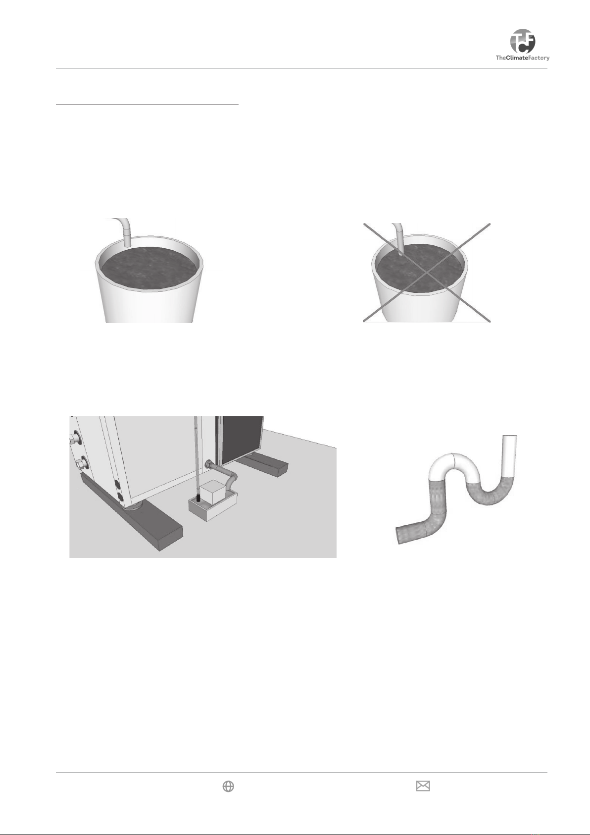
Note: Refrigerant hoses may not be kinked or installed at an acute angle. If they are kinked even briey, they
must be thrown away, a 100% leak will occur at this kink. The hoses must be placed at and must not be pu-
lled. The hoses may not be shortened or extended self. The connections on both the indoor and the outdoor unit
should rst be tightened by hand. After this, the connections are tightened with two spanners, do not tighten too
hard. The hoses should be supported, they may not hang on the indoor or outdoor unit, if they hang they will
buckle under their own weight.

THE CLIMATE FACTORY/USER MANUALS/OPTICLIMATE SPLIT (INVERTER)
www.theclimatefactory.com info@theclimatefactory.com
© The Climate Factory
WATER-SIDED CONNECTIONS
Discharge of the condensation water
The unit will also dehumidify the air during cooling. The moisture extracted from the air comes into the conden-
sation drain. The condensation drain is connected to a sturdy garden hose or a pipeline that does not bend
easily. The condensation water drips from the hose, which can be connected to the drain pipe. The condensate
can also be used as feed water. The cooling block has been adjusted to prevent metals or oxides from entering
the condensate. This is ideal when the only feed water available is hard water.
The drain pipe of the condensation water may not have loops and may not be put under the water level in a
drum. If the unit is installed at the same level or lower than the drain or sewer, a condensation lift pump can
collect the water.
This small lift pump pumps the water through a hose of 9mm to a height of 4 metres into the drain. Stronger
pumps are also available.
The drain to the pump must not be under the water level and the pipe may not have loops as shown above.
It’s possible that too much air is sucked in through the condensation water pipe causing the condensate water
not to drain properly.
Then there is too much resistance in the intake system. Dimension hoses of e.g. a plenum box as large as
possible and ensure that during operation all panels are mounted on the unit. A special syphon can also be
mounted. Ask your dealer.
Drain pump of the condensation water incorrect drain installation
The unit is now installed and ready to use

THE CLIMATE FACTORY/USER MANUALS/OPTICLIMATE SPLIT (INVERTER)
www.theclimatefactory.com info@theclimatefactory.com
© The Climate Factory
PUTTING INTO OPERATION
=
=
T=
FN =
S=
R=
M=
On/Off =
Temp up / scroll
Temp down / scroll
Press and release to set the time / press and hold to set the timer
Fan speed
Press and release to read Sensors / press and hold to bring up the Menu
Press and release to conrm / press and hold to delete error codes
Press and release to switch between day and night mode.
Press and hold to turn automatic light cell mode on/off.
On/Off Turn unit on/off or conrm menu option.
1) On/Off key
The unit is switched On or Off using the On/Off key. The LED will be green when the unit is On. The LED will
be red when the unit is Off. In case of malfunctioning, the LED will ash red and green. The On/Off key is also
used to conrm a menu selection.
2) Mode key M
Pressing the mode key will switch the mode from day mode (cooling) to night mode (heating/dehumidifying).
The display will show a lit snowake in day mode and a sun with drops of water in night mode.
3) Fan speed key Fn
This key is used for selecting the air speed of the fan. The sequence is as follows:
The speed changes whenever the Fn key is pressed. If you select the automatic fan mode in the Cool mode,
the unit will ventilate more or less depending on the need for cooling.
By selecting day or night with the mode key a different fan speed can be chosen for both day and night. For the
night we recommend the lowest fan speed for heating and dehumidifying. If a great deal must be dehumidied
during the night, the fan speed can be set to position 2 or 3.
Temperatures for the day and night can be set using the mode function.
These can be changed later, if required.
A
Remote Control
Automatic Low Medium High

THE CLIMATE FACTORY/USER MANUALS/OPTICLIMATE SPLIT (INVERTER)
www.theclimatefactory.com info@theclimatefactory.com
© The Climate Factory
PUTTING INTO OPERATION
Inverter
The OptiClimate inverter models adjust the cooling capacity to the need. Non-Inverter models operate on
an on / off basis, while the inverter models run the compressor harder/ softer when more or respectively
less cooling capacity is required. This provides an even more stable climate and prevents the frequent tripping
of the unit in case of over capacity.
The inverter function operates on the basis of the fan speed. This means that the fan, in the day position, should
be set to automatic using the remote control (FN). If the fans are set at a xed speed, the inverter function is
switched off and the compressor also runs at a xed speed. (resp. low / middle / high). For the night position,
we recommend that you always use the low setting.
4) Temperature setting
Users can set the temperature from 16°C to 34°C.Pressing the or key will show the set temperature SET
TEMP on the display. By pressing it once more, you can set the required temperature. The set temperature will
be saved and stored after 3 seconds. Switching between day and night temperatures is done using the M
mode key.
5) Time Setting T key
Press the Tkey once to select the hours and then press the or key to change the hours. Press the Tkey again,
and the minutes will ash and then press the or key to change the minutes. Now press the Rkey to conrm
the hours and minutes that you entered.
6) Automatic Light Cell setting (Day /Night programme)
The automatic moisture meter in the PRO3 series has a light cell, which switches to the day mode when it sees
the light is on and to the night mode when the light is off. Only the Day/Night temperatures have to be set,
the rest is done automatically.
If you want to set the unit manually, the automatic light cell can be switched off and the unit will operate ma-
nually. By pressing the Mkey for 3 seconds, the mode switches from light cell to manual. By pressing the M
key again for 3 seconds, the mode switches from manual to light cell. If the automatic light cell is activated,
the display shows an A.
The external automatic moisture meter for the light cell should be connected to the terminal strip in the electrical
compartment (terminals 12, 14 and 18). Otherwise the unit will remain in the night mode because light is not
detected. This is connected by default.
7) Timer Setting (DAY/NIGHT programme)
As a general rule, we recommend using the automatic light cell mode. Only set the timer if you do not
want to work with the light cell!
This function can be used to set the DAY/NIGHT programme. The programme restarts every day regardless of
which day it is. If the timer is set, the display will show the clock icon next to the time.
Press the Tkey for 2 seconds. When “---”, ON becomes visible, you can change the timer setting. Pressing
the or key will allow you to set the hours of the ON time. Pressing the Tkey again will allow you to set the
minutes of the ON time. The ON time is the time that the unit will start to cool.
Pressing the Tkey again will allow you to set the OFF time. The OFF time is the time that the unit will start to
heat/ dehumidify. If the timer is not set yet, the display will show “--:--” or the time that was already set.
Nota: It is important to note that when the Timer setting is programmed the automatic light cell mode is
deactivated. Therefore, install a Timer only if you want to use advanced options. The Timer mode is
active when a clock icon appears in the display.

THE CLIMATE FACTORY/USER MANUALS/OPTICLIMATE SPLIT (INVERTER)
www.theclimatefactory.com info@theclimatefactory.com
© The Climate Factory
PUTTING INTO OPERATION
Example:
The unit must cool between 8:00 AM and 8:00 PM.
The ON time should then be set to 8:00 AM
and the OFF time to 8:00 PM
AM = after midnight (from 0:00 to 12:00 hours)
PM = after noon (from 12:00 to 24:00 hours)
1:00 AM equals 01:00
2:00 AM equals 02:00
3:00 AM equals 03:00
4:00 AM equals 04:00
5:00 AM equals 05:00
6:00 AM equals 06:00
7:00 AM equals 07:00
8:00 AM equals 08:00
9:00 AM equals 09:00
10:00 AM equals 10:00
11:00 AM equals 11:00
12:00 PM equals 12:00
1:00 PM equals 13:00
2:00 PM equals 14:00
3:00 PM equals 15:00
4:00 PM equals 16:00
5:00 PM equals 17:00
6:00 PM equals 18:00
7:00 PM equals 19:00
8:00 PM equals 20:00
9:00 PM equals 21:00
10:00 PM equals 22:00
11:00 PM equals 23:00
12:00 AM equals 00:00
Deleting the time when setting the timer (switching off the timer)
Press the Rkey, and the time is deleted. The display will show “--:--”. CLOSING: Press the Tkey three times to
close immediately or wait 10 seconds to close automatically.
The settings of the current time and the timer settings
should run synchronously with the times of the control panel.
All clocks must run synchronously when the timer function
is used.
8) Using the automatic moisture meter for dehumidifying during the night
The automatic moisture meter can be set to the required maximum air humidity during the night. If the Night
mode is active and the automatic moisture meter indicates that the unit should dehumidify, the Drop icon starts
to ash. During dehumidication the electric heating elements will be activated for the PRO3. This is not the
same with PRO4.
Dehumidification during the day (only PRO4)
Both the PRO3 and the PRO4 will always dehumidify as long as there’s a demand for cooling. However, the
PRO4 can also dehumidify when no cooling is required. This function can be activated by setting option D:39
to 1 in the menu.
If, for example, a constant air humidity and temperature are required continuously in a climatic chamber, cool
at night must be activated in the menu option D:04. By pressing and holding the Mkey the light cell is deacti-
vated and by pressing and releasing the M key a choice must be made for the night setting. The unit can now
cool, heat and dehumidify, while also controlling the humidity at a xed temperature value.

THE CLIMATE FACTORY/USER MANUALS/OPTICLIMATE SPLIT (INVERTER)
www.theclimatefactory.com info@theclimatefactory.com
© The Climate Factory
PUTTING INTO OPERATION
9) Reading function for the temperature sensors
Press the Skey and the sensor will show the temperatures. The number and temperature of the sensors will
show in the spot of the clock. Pressing the and keys will allow users to select the reading of the various
sensors.
CLOSING: Press the Skey to close immediately or wait 60 seconds to close automatically.
C:01= Temperature of cooling block
C:02= Temperature of refrigerant outdoor unit (liquid / return)
C:03= Temperature room 2 (only in case of a dual room conguration, now -40°C)
C:04= Intake (warm) air temperature
C:05= Outlet air temperature
C:06= Temperature of low-pressure (for compressor)
C:07= Temperature of outdoor air (with outdoor unit)
10) Reading function for the error codes
The unit malfunctions if the ON/OFF LED ashes red and green. E:XX will show the actual error code. If the
problem is solved automatically, the error code will disappear.
The error log (alarm history) in located at the bottom in the display of the remote control. If an error occurs,
the error will be continuously visible at the bottom of the display, even if the error has been solved. This way
a malfunction or incorrect setting that is about to come up can be noticed and/or resolved at an early stage.
Deleting the error log (alarm history)
When resolved, errors in the log can be deleted by pressing and holding the Rkey.
Error codes
Nota: Keep the alarm history clear so that problems can be easily resolved at an early stage!

THE CLIMATE FACTORY/USER MANUALS/OPTICLIMATE SPLIT (INVERTER)
www.theclimatefactory.com info@theclimatefactory.com
© The Climate Factory
SETTINGS (SET-UP)
11) Alarm port
The printed circuit-board has an alarm port, which makes contact when an alarm or error occurs. This
contact can be connected to an alarm system or SMS (GSM) detector.
12) Compressor Active mode
If the compressor operates, the display will show the Compressor icon at the bottom right-hand side,
it will disappear when the compressor is turned off. The compressor only operates during the DAY
period, if the set temperature is exceeded, and during the NIGHT period, if the set air humidity is
exceeded. In PRO4, the compressor runs even when there is no cooling demand in case of excessi-
vely high humidity during the daytime.
13) Heating Elements Active mode
If the heating elements are turned on, the display will show the Hot Air icon at the bottom right-hand
side, it will disappear when the heating elements are turned off. The heating elements only operate
during the NIGHT period, if the temperature reaches a value below the set value.
14) Fan of outdoor unit active.
When this symbol appears in the display, the fan(s) on the outdoor unit is running. If you switch off
the fan(s), the symbol disappears. The fan(s) on the outdoor unit only run when needed.
SETTINGS (SET-UP)
Use the or key to change a setting. You press the ON/OFF key to conrm. If you do not want to change
anything and exit the menu, press the Rkey. The settings range from D:01 to D:32. Do not adjust settings D:16
to D:22. These are factory settings.
To restore the factory settings, press and hold the Mkey until the Settings menu opens. All settings will now be
restored to factory settings. Conrm this with the on/off key.
D:01 Switching the heating elements on/off
Depending on the model, an OptiClimate has 2 or 3 heating elements. The heating elements of 1-phase
systems are connected to 1 phase and the heating elements of 3-phase systems are divided over all phases.
Each of these elements can be switched on and off individually in the Settings menu. If a central heating sys-
tem is used for heating, for example, all of these heating elements can also be switched off at the same time.
Setting:
D:1 = 3 means all three elements will heat.
D:1 = 2 means two elements will heat.
D:1 = 1 means one element will heat.
D:1 = 0 means all elements are off.
D:02 Temperature safeguard
If the room temperature exceeds 35°C, terminals 15 and 16 on the terminal strip of the unit will switch off the
heating elements in the rooms that have to be cooled. The switch-off temperature can be changed using the
D:02 setting. The minimum temperature for switching off is 30°C and the maximum temperature is 40°C. If
the temperature drops below the set temperature for cooling mode again, the safeguard will switch off and
restart the heat sources.
The safeguard does not affect the operation of the OptiClimate. However, the display will show the error
message E:15. (also see the fault code list)
D:03 Auto Restart after power interruption
If the power is interrupted when the unit is on and the power is restored, the unit will switch on by default. If
you want the unit to remain off after a power interruption caused by an external fault, you should change the
D:03 setting.

THE CLIMATE FACTORY/USER MANUALS/OPTICLIMATE SPLIT (INVERTER)
www.theclimatefactory.com info@theclimatefactory.com
© The Climate Factory
SETTINGS (SET-UP)
Setting:
D:03 = 0 means Auto Restart is off.
D:03 = 1 means Auto Restart is on. This is the default setting. The display will show error code 14 in case of power
interruption. See also the fault code list.
D:04 Night cooling (Cool at Night) on/off.
Using this setting, the night cooling can be switched on.
D:04 = 0 means Cool at Night is off. This is the default setting.
D:04 = 1 means Cool at Night is on.
If in the timer off mode the minimum temperature is, for example, set to 22°C, the unit will cool the room to 22°C
in the night mode. If the room temperature drops below 22°C, the unit will begin to heat the room. This function
is useful in warm climates, in a very well-insulated room or with other sources of heat that cannot be switched off.
When the Cool at Night function is active a moon icon will be shown on the display.
D:05 Pre-Heating on/off.
Pre-heating can be switched on using this setting.
D:05 = 0 means Pre-Heating is off. This is the default setting.
D:05 = 1 means Pre-Heating is on.
If Pre-Heating is switched on, the unit will heat the room up to the set cooling mode (day) temperature one hour
before daybreak (timer is on). At the beginning of the day, the room will be at the right temperature. Besides the
advantage of giving the day temperature a jump-start, this also prevents the cold parts of the unit from becoming
wet, which reduces or prevents mould build-up.
Note: Only works in conjunction with the timer and not in the light cell mode!
D:06 Slow cool-down (post-heating) on/off.
Slow cool-down (post-heating) can be switched on using this setting.
D:06 = 0 means Slow Cool-Down is off. This is the default setting.
D:06 = 1 means Slow Cool-Down is on.
If Slow Cool-Down is switched on, the unit will slowly cool the room until one hour after the end of the day.
Note: Only works in conjunction with the timer and not in the light cell mode!
D:07 Dual Room (cooling two rooms 12h by 12h) on/off.
Using this setting, you can switch on/off the cooling of two rooms alternately.
D:07 = 0 means Dual Room operation is off. This is the default setting.
D:07 = 1 means Dual Room operation is on. If the Dual Room function is active, the display will show the house
icon at the bottom right-hand side.
To use this function, you will have to order a three-way valve and a connection set consisting of a three-way valve,
plenum box, second temperature sensor and an extensive installation/user manual.
D:08 Alarm port N.O. (Normally Open) or N.C. (Normally Closed)
Using this setting, the alarm port can be adjusted.
D:08 = 0 means N.C. Normally closed. This is the default setting.
D:08 = 1 means N.O. Normally open.
Refer to the user manual for the correct settings of the SMS (GSM) detector or the alarm system that should be
connected.
D:09 Not applicable
D:10 Timer port
If D:10=0, ports 15 and 16 will interrupt the High Temperature alarm. If D:10=1, the high temp alarm will not occur
through these contacts. With D:10=1, port 16 is common and ports 16 & 17 will be each other’s alternate con-
tacts. The clock of the OptiClimate (OC) will operate these make-and-break contacts and the clock/timer of the OC
can replace the clock on the control panel. The lamps will operate synchronous with the cooling mode of the OC.
To install a High Temperature safeguard, contact 16 should be aligned with the alarm port on the printed cir-
cuit-board. If there is a High Temperature alarm, this alarm will interrupt the timer’s signal and the temperature safe-
guard will still operate. The setting of the alarm port should then be the standard setting (0 = N.C.).

THE CLIMATE FACTORY/USER MANUALS/OPTICLIMATE SPLIT (INVERTER)
www.theclimatefactory.com info@theclimatefactory.com
© The Climate Factory
SETTINGS (SET-UP)
D:11 Hysteresis of the temperature
Using this setting, you can adjust the hysteresis (bandwidth) of the temperature control. This is the temperature diffe-
rence required to switch the compressor on and off.
Setting: D:11 = 2 means the hysteresis is 2. This is the default setting.
The hysteresis can be set from 1°C to 4°C in steps of 0.5°C. If, for example, the day temperature is set to 28°C
and the hysteresis to 2°C, the unit will start to cool at 29°C and stop cooling at 27°C. To shorten the hysteresis
effectively, the resting time of the (D:27)
D:12 Minimum adjustable heating temperature
Using this setting, you can change the minimum adjustable heating temperature. The adjustable values in D:12 are:
default = 16°C, max. = 20°C, min. = 10°C.
D:13 Maximum adjustable heating temperature
Using this setting, you can change the maximum adjustable heating temperature. The adjustable values in D:13 are:
default = 35°C, max. = 50°C, min. = 25°C.
D:14 Minimum adjustable cooling temperature
Using this setting, you can change the minimum adjustable cooling temperature. The adjustable values in D:14 are:
default = 16°C, max. = 20°C, min. = 10°C.
D:15 Maximum adjustable cooling temperature
Using this setting, you can change the maximum adjustable cooling temperature. The adjustable values in D:15 are:
default = 35°C, max. = 35°C, min. = 25°C.
D:16 Not applicable
D:17 Anti-freeze protection of the cooling block
Using this setting, you can determine at which temperature the Anti-Freeze alarm of the cooling block is activated.
The settings in D:17 are: default = 0°C, max. = 5°C, min. = -2°C.
D:18 Not applicable
D:19 Not applicable
D:20 Not applicable
D:21 Cooling block too hot
Using this setting, you can determine at which temperature the Cooling block too hot alarm is activated. The settings
in D:21are: default = 4°C, max. = 0°C, min. = 10°C and 1°C. To activate the alarm, the temperature has to be
too high for a certain period of time. The time is determined by D:22. D:21 and D:22 jointly determine when Error
11 is activated.
D:22 Duration of cooling block over heating
Using this setting, you can determine how long it takes before a Cooling block too hot alarm is given. The settings
in D:22 are 30 mins (standard), 40 mins (maximum), 20 mins (minimum).
The temperature level is determined by D: 21. D:21 and D:22 jointly determine when E:11 is activated.
D:23 Temperature compensation of the room temperature sensor
Using this setting, you can calibrate the room temperature sensor. The setting can be changed if the indication on
the display does not correspond with reality. The settings in D:23 are: default = 0°C, max. = 5°C, min. = -5°C
and can be set in 0.5°C increments.
D:24 Temperature compensation of the cooling block temperature sensor
Using this setting, you can calibrate the cooling block temperature sensor. The settings in D:24 are: default = 0°C,
max. = 5°C, min. = -5°C and can be set in 0.5°C increments.

THE CLIMATE FACTORY/USER MANUALS/OPTICLIMATE SPLIT (INVERTER)
www.theclimatefactory.com info@theclimatefactory.com
© The Climate Factory
INSPECTION AND MAINTENANCE
D:25 Temperature of compensating refrigerant return outdoor unit
With this option, the temperature sensor can measure the temperature of the return gas to be calibrated from
the outdoor unit. The setting in D:25 is default = 0°C, max. = 5 °C, min. = -5°C and can be set in 0.5°C
increments.
D:26 Temperature compensation of the Dual Room temperature sensor
With this setting, you can calibrate the second room temperature sensor in the Dual Room conguration. The
settings in D:26 are: default = 0°C, max. = 5°C, min. = -5°C and can be set in 0.5°C increments.
D:27 Resting time of the compressor
Using this setting, you can adjust the resting time between Compressor Off and Compressor On.
Setting: D:27 = 15 means the idle time is 15 seconds. This is the default setting. This setting may be used if
the temperature values in the room change too much because of the time that the compressor is in idle mode.
D:28 Not applicable
D:29 Display lighting
Using this option, you can switch the lighting in the display of the remote control on and off. 0 = Automatic
(default)
1 = Always on
D:30 Fan outdoor unit on / off.
This option determines at which Liquid / Return refrigerant temperature the fan(s) of the outdoor unit will switch
on. The default setting is 27°C. The setting can be changed from 23°C to 33°C.
D:31 Waiting time of outdoor unit fan
With this function, the waiting time can be set and then the fan will run on the outdoor unit after the compressor
is switched on. The standard setting is 30 seconds. (3). The time can be changed between 0 and 90 se-
conds,. (0 to 9). In case of high ambient temperatures, it may be desirable to change the time to 10 seconds,.
In case of cold outdoor temperatures, the setting should be 30 seconds.
D:32 Outdoor air temperature too high.
Standard setting is 40°C. The setting can be changed from 35°C to 45°C
D:33 Temperature of compensating intake (warm) air
Standard setting is 0°C. The setting can be changed from -5°C to +5°C.
D:34 Temperature of compensating outlet (cold) air
Standard setting is 0°C. The setting can be changed from -5°C to +5°C
D:35 Temperature of compensating refrigerant low pressure side
Standard setting is 0°C. The setting can be changed from -5°C to +5°C
D:36 Temperature of compensating outdoor air temperature sensor
Standard setting is 0°C. The setting can be changed from -5°C to +5°C
D:37 Buzzer on / off.
0=off / 1=on

THE CLIMATE FACTORY/USER MANUALS/OPTICLIMATE SPLIT (INVERTER)
www.theclimatefactory.com info@theclimatefactory.com
© The Climate Factory
FAULT ANALYSIS AND ERROR MESSAGES
D:38 Celsius / Fahrenheit
0=C/1=Fh
D:39 Super dehumidification in day mode is on / off.
0=off / 1=on
INSPECTION AND MAINTENANCE
Frequently check whether all couplings are properly tightened. Also check that there are no leaks. The dust
lter at the backside of the unit should be checked every 10-12 weeks for dust accumulation. If the lter has
a layer of dust, the dust should be removed using a vacuum cleaner.
The carbon lter should be replaced every 10-12 weeks in order to guarantee proper operation of the unit.
This is essential and should not be forgotten! If this is not carried out, the lter will break down sooner than
normal. To replace the carbon lter, you rst have to remove the dust lter.
Note : If you want to work with a humidifier, make sure that it is connected to a reverse osmosis filter or
scale filter. Fan faults caused by lime deposits are not covered under the warranty.
If the dust lter is still clogged with white particles when using a humidier in conjunction with a scale lter,
then an osmosis lter is required. The water is too hard to use with a scale lter. There is no need to use a
humidier if the space is not too large.
FAULT ANALYSIS AND ERROR MESSAGES
If the unit does not switch on and the remote control display and the LEDs on the printed circuit-board are off,
most likely there is no power supply. It is also possible that the internal fuse has blown. This fuse is located
near the printed circuit-board in a synthetic housing.
If there is power (the LED on the printed circuit-board ashes and the remote control display shows E:01), but
the unit does not switch on, two of the three phases should probably be switched. It does not matter which
ones of the three phases are switched.
If the fuse circuit breaker burst when the unit has to start cooling, most likely a fuse of the wrong value or
incorrect type was installed. Check the technical specications (page 8) for the correct details.
If the unit makes strange noises or is cooling poorly, check the manometer to ensure that the pointer is not
pointing too far to the right from the centre of the screen and check that the outdoor temperature (C:07) does
not exceed 50°C.
If that is the case, make sure that the outdoor unit receives more / colder air and check whether the pointer
of the manometer drops.
If water drips from the sides of the unit, you have a problem with the condensation water drainage. Check
whether the unit has sufcient fall (see the Mounting section) using a spirit level. It is also possible that the
condensation hose has too many loops/bends or is blocked.

THE CLIMATE FACTORY/USER MANUALS/OPTICLIMATE SPLIT (INVERTER)
www.theclimatefactory.com info@theclimatefactory.com
© The Climate Factory
FAULT ANALYSIS AND ERROR MESSAGES
This manual suits for next models
1
Table of contents
Other OPTICLIMATE Inverter manuals
Popular Inverter manuals by other brands

SMA
SMA SUNNY ISLAND 3.0M Quick reference guide

Lenze
Lenze L-force 8400 Series Reference manual

SamplexPower
SamplexPower PST-1500-12 owner's manual

Black & Decker
Black & Decker POWER TO GO CPI100B instruction manual

Generac Power Systems
Generac Power Systems 0K2502SPFR owner's manual

WEG
WEG MVW3000 Series Programming manual

Vector
Vector MAXX SST VEC053D Owner's manual & warranty information

GYS
GYS CONVERGYS 300 manual

Icel Manaus
Icel Manaus GV-2005 user manual

CyberPower
CyberPower CPSPV3600ETL-IN SLV user manual

YASKAWA
YASKAWA VS-606V7 Series instruction manual

Mitsubishi Electric
Mitsubishi Electric FR-A802-E instruction manual