Opticon EBS-50 User manual

1
Specifications manual
EBS-50 Smart Base station
ESL base station with built-in server

2
The information in this document is subject to change without notice.
© 2020 Opticon. All rights reserved.
This manual may not, in whole or in part, be copied, photocopied, reproduced, translated, or
converted to any electronic or machine-readable form without prior written consent from
Opticon.
Limited Warranty and Disclaimers
Please read this manual carefully before installing or using the product.
Serial Number
A serial number appears on all Opticon products. This official registration number is directly
related to the device purchased. Do not remove the serial number from your Opticon device.
Removing the serial number voids the warranty.
Warranty
Unless otherwise agreed in a written contract, all Opticon products are warranted against
defects in materials and workmanship for two years after purchase excluding batteries. Opticon
will repair or, at its option, replace products that are defective in materials or workmanship with
proper use during the warranty period. Opticon is not liable for damages caused by
modifications made by a customer. In such cases, standard repair charges will apply. If a
product is returned under warranty and no defect is found, standard repair charges will apply.
Opticon assumes no liability for any direct, indirect, consequential or incidental damages arising
out of use or inability to use both the hardware and software, even if Opticon has been informed
about the possibility of such damages.
Packaging
The packing materials are recyclable. Damage caused by improper packaging during shipment
is not covered by the warranty.
Trademarks
Trademarks used are the property of their respective owners.
Opticon Inc. and Opticon Sensors Europe B.V. are wholly owned subsidiaries of
OPTOELECTRONICS Co., Ltd., 12-17, Tsukagoshi 4-chome, Warabi-shi, Saitama, Japan 335-
0002. TEL +81-(0) 48-446-1183; FAX +81-(0) 48-446-1184
Support
USA
Europe
Phone: 800-636-0090
Phone: +31235692728
Email: support@opticonusa.com
Email: support@opticon.com
Web: www.opticonusa.com
Web: www.opticon.com

3
Revision History
EBS-50 Specifications Manual
Edition
Date
Page
Section
Description of Changes
1st
October 21, 2020
-
-
Initial release.

4
Contents
1Overview............................................................................................................................ 6
2About the EBS-50 Smart base station................................................................................ 7
3Physical Features............................................................................................................... 8
3.1 Weight........................................................................................................................ 8
3.2 Dimensions................................................................................................................. 8
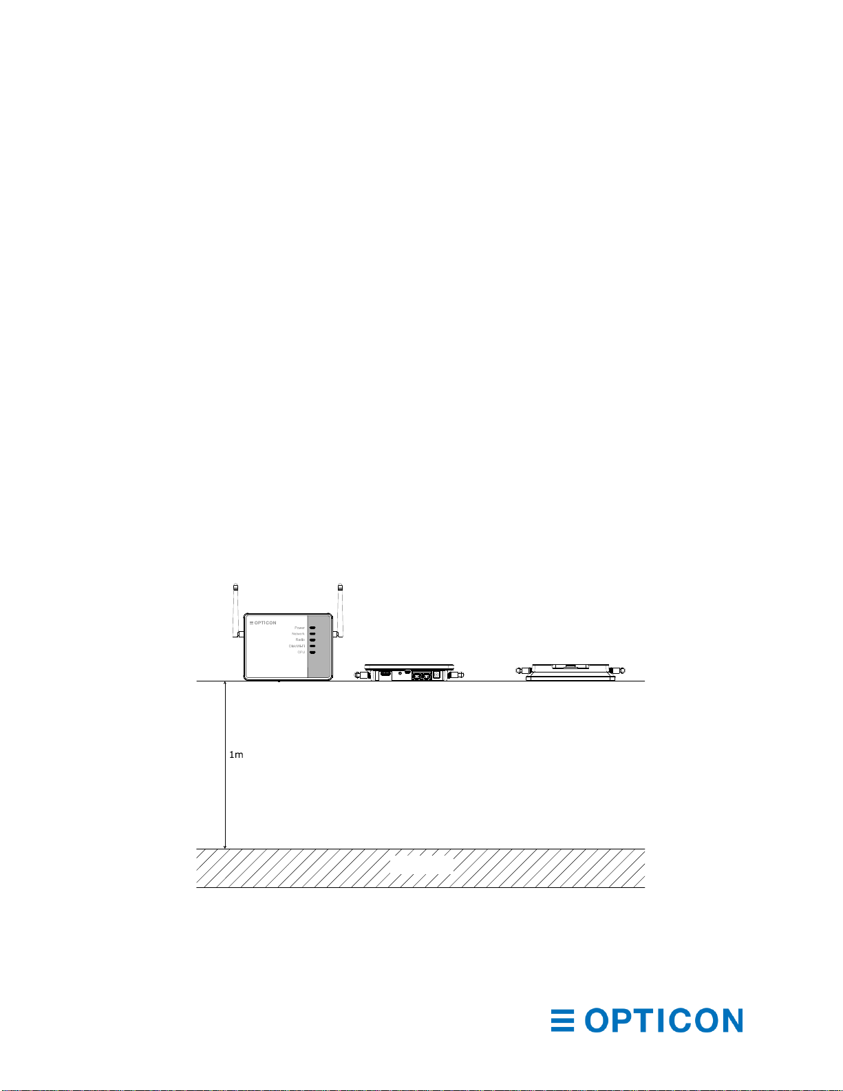
3.3 Maximum total height.................................................................................................. 8
3.4 Mounting..................................................................................................................... 9
4Environmental Specifications ............................................................................................10
4.1 Operating Temperature and Humidity........................................................................10
4.2 Storage Temperature and Humidity...........................................................................10
4.3 Static Electricity.........................................................................................................10
4.4 Drop resistance. ........................................................................................................10
4.5 Dust and Drip Proof...................................................................................................10
5Electrical specifications .....................................................................................................11
5.1 Computer...................................................................................................................11
5.2 Radio.........................................................................................................................11
5.3 Electrical Characteristics TBD ...................................................................................11
6Interfaces..........................................................................................................................12
6.1 USB-Host ..................................................................................................................12
6.2 Reset switch..............................................................................................................13
6.3 USB-OTG..................................................................................................................13
6.4 Ethernet ports............................................................................................................13
6.5 DC input connector....................................................................................................13
7Indicators ..........................................................................................................................14
8Labels ...............................................................................................................................15
8.1 Product label .............................................................................................................15
8.2 Anatel label................................................................................................................15
8.3 Label positions...........................................................................................................16
8.4 White box label..........................................................................................................16
8.5 Shipment box label....................................................................................................17
9Packing.............................................................................................................................18
9.1 Individual packing......................................................................................................18
9.2 Shipment packing......................................................................................................19
10 Software configuration.......................................................................................................20

5
10.1 Basic setup................................................................................................................20
10.2 ESL Server setup ......................................................................................................24
Table of Figures
Figure 1: EBS-50 Dimensions.......................................................................................................................8
Figure 2: EBS-50 Maximum height...............................................................................................................8
Figure 3: Mounting plate ...............................................................................................................................9
Figure 4: Attaching and detaching the EBS-50 to the mounting plate..........................................................9
Figure 5: Drop test ......................................................................................................................................10
Figure 6: Interfaces .....................................................................................................................................12
Figure 7: Wi-Fi Dongle................................................................................................................................12
Figure 8: DC plug dimensions.....................................................................................................................13
Figure 9: LED Indicators .............................................................................................................................14
Figure 10: Product label..............................................................................................................................15
Figure 11: Anatel label................................................................................................................................15
Figure 12: Label position.............................................................................................................................16
Figure 13: White box label ..........................................................................................................................16
Figure 14: Shipment box label ....................................................................................................................17
Figure 15: Individual packing ......................................................................................................................18
Figure 16: Shipment packing ......................................................................................................................19

6
1Overview
The EBS-50 is a base station, equipped with two 2.4GHz radios for data communication with
Opticon’s electronic shelf labels (ESLs) plus a built-in computer that runs the Opticon ESL
server. The EBS-50 allows for a very compact ESL system. Everything needed for a running
system is the EBS-50 itself, a power supply, and an Ethernet connection (Wi-Fi is optional) plus
of course the ESLs themselves.
The product uses Direct Sequence Spread Spectrum RF technology that allows for an ultra-low
power consumption combined with a reduced sensitivity to background noise. That means less
interference by other radios that operate in the 2.4GHz band. The radio protocol that is used is
based on the IEEE 802.15.4 standard that specifies the physical layer and media access control
for low-rate wireless personal area networks.
The base station can run a local price/article database on its own flash disk that can be updated
remotely, either manually or automatically with database triggers, or it can be configured to use
an external database. With the information from the database, the EBS-50 can create images
for the ESLs that are connected to it and send those to the corresponding ESLs. Having the
option to run the database either locally or externally allows for a very flexible setup of the ESL
system, from a very small stand-alone system to very large cloud-based system where the EBS-
50 is then the gateway in the shop to the Internet. In that case, a central dashboard server is
required where the EBS-50 can upload status information.
The EBS-50 can be controlled via a web browser on any device that connects to the same
network. There is no need to connect a keyboard and/or monitor to it, which makes it easier to
install the EBS-50 in the most convenient location. Maintenance and configuration to the EBS-
50 can then be done from any location provided that that location is connected to the same
network as the EBS-50. It is even possible to do that from a remote location but in that case, a
VPN tunnel is required because of safety concerns. The EBS-50 can setup that VPN tunnel by
itself, provided that the remote location already has a VPN server running but this is usually not
needed. The EBS-50s can download configuration and maintenance files from a central server
and will store its status information there.

7
2About the EBS-50 Smart base station
The most important features of the EBS-50 are listed below.
•Small and compact: The EBS-50 is not bigger than a regular base station but is
powerful enough to handle all basic tasks of a separate ESL server.
•Built-in computer: The built-in computer runs a Linux operating system plus Opticon’s
ESL server, and both are optimized for each other. A separate computer will always
have a hassle with libraries and other parts of the operating system that may not be fully
compatible or not installed, whereas the EBS-50 comes pre-configured with the correct
software.
•No separate computer needed: Shop owners usually do not like a separate computer
that requires maintenance and updates, especially when this is a Windows computer.
The EBS-50 removes the need for this since it has a built-in computer and updates are
much easier to do than with a normal computer. The EBS-50 can update itself
automatically from a remote server, but updates can also be done with a USB-stick. The
frequency of updates is much lower than with a full blown (Linux or Windows) computer
since the EBS-50 only contains the software that is really needed to run the server.
•Power over Ethernet (PoE): PoE is supported on one of the Ethernet ports to make
installation even more simple. When a location has PoE switches, the EBS-50 does not
need a separate power supply and so no wall socket is needed.
•Two Ethernet ports: The EBS-50 comes with two gigabit Ethernet ports, and a built-in
switch and router. This makes larger setups, where more than one base station is
required, much easier as it is possible to daisy-chain the base stations via the 2nd
Ethernet port while the first port is used for the connection with the LAN.
•USB ports: Two USB ports are available. One is a USB-host port, with a USB-A style
connector and the other is a USB-OTG port, with a micro USB style connector. The main
use of the host port is for a Wi-Fi dongle and Opticon will come with a list of approved
dongles for which the driver is already installed. This port however can also be used for
software updates that come on a USB-stick for those situations where the EBS-50
cannot connect to the Internet.

8
3Physical Features
3.1 Weight
The weight of the EBS-50 is approx. 250g (TBD)
3.2 Dimensions
The dimensions of the EBS-50 base station: 145 x 110 x 27.1 mm (179.6x158.3x27.1 mm with
the antennas mounted alongside the main housing).
Figure 1: EBS-50 Dimensions
3.3 Maximum total height
The antennas can be rotated, but the most common position is vertical. The height with both
antennas in this position and with the base station horizontal, mounted on the mounting plate is
95.3mm.
Figure 2: EBS-50 Maximum height

9
Use a flat screwdriver and push
here to unlock the EBS-50
3.4 Mounting
The EBS-50 comes with a mounting plate for easy mounting to e.g. a wall or the ceiling. The
EBS-50 can slide over the mounting plate to click and lock it into place. To unlock it, use a flat
screwdriver to push the locking tap down and then slide the EBS-50 away from the screwdriver.
Figure 3: Mounting plate
The mounting plate can be attached to a wall with two screws, spaced 40mm apart. The top of
the mounting plate, where the Opticon logo is visible, should face forward, away from the wall.
Once the mounting plate is attached, the EBS-50 can slide over the mounting plate until it locks
into position.
Figure 4: Attaching and detaching the EBS-50 to the mounting plate
Slide the EBS-50 over the mounting
plate in this direction to lock it in place

10
4Environmental Specifications
4.1 Operating Temperature and Humidity
Temperature: 0 to 70° C
Humidity: 20% to 85% RH
4.2 Storage Temperature and Humidity
Temperature: -20 to 70° C
Humidity: 20% to 85% RH
4.3 Static Electricity
Air discharge:
± 8 kV (No malfunction / Automatic recovery)
± 15 kV (No damage but operator involvement may be required)
Contact discharge:
± 4 kV (No malfunction / Automatic recovery)
± 8 kV (No damage but operator involvement may be required)
4.4 Drop resistance.
The EBS-50 has withstood the following drop test:
Drop the base station 12 times (3 times at each of 4 orientations), from a height of 1m onto a
concrete floor as shown below. Note the position of the antennas.
Figure 5: Drop test
4.5 Dust and Drip Proof
This product has not undergone any IP tests. The intended use is indoor only.
Concrete

11
5Electrical specifications
5.1 Computer
Item
Specifications
Remarks
CPU
Type
Dual core ARM Cortex A7
1.2GHz clock speed
Single core ARM Cortex M4
200MHz clock speed
Memory
Storage
64GByte eMMC
eMMC flash disk
RAM
512Mbyte
DDR3 memory
Interfaces
2 x Ethernet
10/100/1000 gigabit
Port 1 supports PoE
Class 3.
1 x USB Host
USB-A type dongles supported
1 x USB-OTG
Micro USB type connector
5.2 Radio
Items
Specifications
Remarks
Radio
Modulation
DSSS
Frequency
2400 ~ 2495 MHz
Channel 11 ~ Channel 261
Channels 27~28 are available
on request.2
Baud rate
250 Kbits / second
Number of independent
radios
2
1Channels 1~10 are reserved for sub-GHz frequencies, which are not supported by the EBS-50.
2Local regulations may not allow the use of these channels.
Parameter
Min
Typ
Max
Unit
Remarks
Receiver sensitivity
-100.3
dBm
1% PER
Output power
5.4
10
21.1
dBm
Configurable
Frequency
2400
2495
MHz
5.3 Electrical Characteristics TBD
Parameter
Min
Typ
Max
Remarks
Operating voltage
DC Input
9 V
12V
16V
PoE Powered
57V
As per PoE standard
Operating power
7W
10W
Either DC powered or PoE powered

12
6Interfaces
The drawing below shows the position of the various interfaces on the EBS-50
Figure 6: Interfaces
Item
Interface
Connector type
Description
1
USB-Host
Female USB type A
For USB gadgets such as a Wi-Fi dongle
2
Reset switch
3
USB-OTG
Female USB micro
4
Ethernet port 1
RJ-45
10/100/1000 Mbps Ethernet with PoE
5
Ethernet port 2
RJ-45
Same as port 1 but without PoE
6
DC Jack
12V DC input
6.1 USB-Host
This interface is meant for a USB dongle such as a USB stick or a Wi-Fi dongle. To protect the
dongle and make it a bit harder for people to take it away, it is in a recessed area. Therefore,
the dongle cannot be too wide. The available size is 18.5x8mm and most small, modern Wi-Fi
dongles will fit in.
Figure 7: Wi-Fi Dongle
Wi-Fi Dongle
placed in the USB
host connector.

13
6.2 Reset switch
The reset switch can be used to reset the EBS-50 to factory default. This can be used for
instance when the operator has made a mistake and has accidentally locked the EBS-50 out
from the network. Since the EBS-50 must be controlled via a web-browser, a working Ethernet
connection is required to change the setup, so when that is not working the reset switch is the
only thing that can bring the EBS-50 back online.
To reset the Ethernet configuration, follow the steps below:
•Remove the power
•Press and hold the reset switch.
•While keeping the switch pressed, apply power (either via the DC jack or PoE)
•Keep the reset key pressed for at least 10 seconds.
When this is done, the Ethernet connection settings are set to automatic (DHCP)
6.3 USB-OTG
This port can be used for various other USB gadgets, but its main purpose is for testing,
debugging and firmware download during the production in the factory.
6.4 Ethernet ports
The EBS-50 has two 10/100/1000 MBits/s Ethernet ports. Port 1 can be used to power the EBS-
50 via Power Over Ethernet (PoE) but can work with non-PoE Ethernet as well. The other port
has no PoE capabilities but is the same otherwise. Both ports are configured as a switch so one
port can be used for instance to connect to the local network, while the other can be used to
daisy-chain other base stations.
6.5 DC input connector
This connector has a center pin with a diameter of 2.1mm and a hole diameter of 6.5mm. The
mating plug should therefore have a center hole of 2.1mm and an outer diameter of 5.5mm as
shown. The center pin is +12V.
Figure 8: DC plug dimensions

14
7Indicators
The EBS-50 has 5 LED indicators that are visible from the top of the device.
Figure 9: LED Indicators
Power. This LED turns red right after the power is applied. The internal computer will then start
running and when it is done with the boot process, the led will turn green. If the LED stays red
for several minutes, a severe problem has occurred. In that case, it may be required install a
fresh operating system via the USB port.
Network. This LED turns green when an Ethernet link is established on LAN port 1 and starts
flashing green when data is received or sent out. This LED turns red when an Ethernet link is
established on LAN port 2 and starts flashing red when data is received or sent out.
Radio. This LED flashes green when radio 1 is active and flashes red when radio 2 is active.
Disk/Wi-Fi.This LED flashes green when the internal disk is accessed, and it flashes red when
the Wi-Fi interface is used (provided that a suitable Wi-Fi dongle is installed)
CPU. This LED flashes green when CPU0 is busy and flashes red when CPU1 is busy.
Apart from these LED indicators, the two Ethernet ports have a link (on the left side) and an
activity LED (on the right side).

15
8Labels
8.1 Product label
The product label shown below is placed on the back side of the base station.
Figure 10: Product label
The label shows product name, article code and the various regulatory logos plus the product’s
Ethernet MAC address. The addresses for the two 802.15.4 radios are derived from this
address. These addresses (both are the same) are essentially the same as the Ethernet
address, but with two bytes extra. Below is a description of those addresses:
Ethernet MAC address: M1M2M3-S1S2S3
802.15.4 MAC address: M1M2M3-SaSbS1S2S3
M1M2M3 defines the manufacturer ID, which is 00126A for Opticon and is the same for both
address types. The bytes that follow the manufacturer ID, define the product number which is
three bytes long for an Ethernet address and 5 bytes for an 802.15.4 address. To convert the
two, we have set SaSb both to zero. So e.g. an Ethernet MAC address of 00126A-45AB23
results in an 802.15.4 address of 00126A-000045AB23.
Material: Base + laminate protection against wear.
Base: PP film, thickness 80µm, backing with glue.
Laminate: PET film, clear, thickness 25µm.
Colors: Black & White
The dimensions of the product label are 50 x 25 mm.
8.2 Anatel label
The Anatel label is a regulatory label required for the Brazilian market. The size and material
specs are the same as those for the product label.
Figure 11: Anatel label

16
8.3 Label positions
The labels are placed as shown below
Figure 12: Label position
8.4 White box label
The white box label is made from plain paper and is meant to show the product number and
serial number. The label size is 60x25mm and the design is shown below.
Figure 13: White box label
The white box label lists the item number and serial number just as on the product label. It also
shows a GTIN barcode that has the Opticon manufacturer number and the article code
encoded.
Model EBS-50
Quantity: 1
*000001*
*14828*
Item:
S/N:
8 7 1 9 9 8 2 1 4 8 2 8 6

17
8.5 Shipment box label
The shipment box label is Opticon’s standard shipment box label and contains information about
the order number, box quantity, manufacturing spec. number, software versions etc. The label
also contains a GTIN barcode. The label is according to Opticon’s shipment box standard rev 9
and the size is 160x105mm.
Figure 14: Shipment box label

18
9Packing
9.1 Individual packing
After putting the base station in a foam bag, it is packed in a white box with the following
accessories:
- Two antennas
- One quick start guide
- The safety instructions
- One mounting plate
The white box size is 19x5.5x15.5cm.
Figure 15: Individual packing

19
9.2 Shipment packing
30 individual EBS-50 boxes are packed into one shipment box.
The weight of the shipment box is 10kg TBD
Figure 16: Shipment packing

20
10 Software configuration
10.1 Basic setup
To start working with the EBS-50, the first step that needs to be done is to connect it to a
network via Ethernet. Once that is done, the EBS-50 can be configured via any computer on the
same network. All that is needed is a web browser. So, start with plugging a network cable into
one of the Ethernet ports and plug the other end in a network socket.
Once the EBS-50 has an Ethernet connection, start a browser on any device (all modern
browsers are supported) and navigate to:
http://EBS50.local
Please note that the EBS50 in this URL is the default hostname that is programmed into the device. It is possible to
configure this in the Network setup, so when this has been changed, the URL is different.
When this is done, the login screen is shown:
The default username is: Admin
The default password is: Admin
Please note that once users are created in the database, this default user and password are automatically deleted.
The users and the roles that are defined there can then be used to login to this page.
Table of contents
Other Opticon Accessories manuals