Optimal 1100 User manual

O P E R A T I N G M A N U A L
FOR
TREE SPADE OPTIMAL 1 1 0 0
MOUNTED ON FORD F550
Manufacturer: Distributor:
Optimal-Vertrieb Opitz GmbH Prichard's Nursery Equipment LLC
Eysoelden M 41 P.O.Box 549
91177 Thalmaessing Portland, TN 37148
Germany U.S.A.
Phone: ++ 49 - 9173 - 79 18 0 Phone: (423) 326 - 0753
Fax: ++ 49 - 9173 - 79 18 49 Fax: (615) 323 - 7667
eMail: info@opitz-optimal.com eMail: sales@optimaltreespades.com
web: www.opitz-optimal.com web: www.optimaltreespades.com

- 1 -
C O N T E N T S
page
Safety Instructions 2
1. Operating Specifications 3
2. Hydraulic Supply 4
3. Operation and Transport 5
4. Care and Maintenance 8
5. Electro-Hydraulic 14
6. Lubrication chart
6.1 Digging Head 15
6.2 Superstructure 16
7. Trouble Shooting 17
8. Spare Parts List 19
9. Warranty

- 2 -
Safety Instructions for OPTIMAL Tree Spade
The operator and his assistant(s) must have read and understood the Operating
Manual before running the tree spade. Furthermore, the operator must be
experienced in driving the truck and he must have studied the relevant truck manual.
Before starting operations, bolts and hydraulic fittings of the tree spade must be checked
to make sure they are free of damage and well tightened.
Defective or loose hose pipes might cause serious injuries and therefore must be
replaced immediately.
The operator is responsible for ensuring that no person is near the tree spade when
in operation; in particular, no one should be standing underneath the raised tree spade or
near shearing and pinching areas, or near the gate, or near blades or near
hydraulic components.
We are advising the user that due to their functional positions and movements the
danger areas cannot be furnished with protective guides.
When sight is limited, an assistant must direct the operator by hand signals.
When driving, the tree spade should be in the lowest possible position. When moving
and working on public roads, the relevant traffic rules and regulations must be
adhered to.
When doing cleaning, maintenance or repair work, lower the tree spade to the ground
and stop the engine of the power unit.
The tree spade must be inspected by an expert on operational reliability annually.
All hydraulic hose pipes must get replaced every six years.
Do not modify the equipment unless the manufacturer has given his approval. Use original
spare parts only.
When digging it might happen that a stone gets caught between two blades and the blades
get bent. This causes tremendous tension in the steel blades. Place the digging head again
into the planting hole and retract the blades. Thereby the stone will come loose. The blades
got a high degree of bending strength and they will regain their former shape. After the stone
has been released, the root ball can be dug again.
Do not try to release the stone by means of a crow bar or other tools!
When travelling, the hydraulic pump must be switched off.

-
2A -
1. Tower: 4. Tower:
7. Frame:
Part N°7118000001 Part N°7118000004 Part N°7118000001
Part N°7118000005
Part N°7118000006
Part N°7118000008
8. Oil - Manifold:
Part N°7118000009
Part N°7118000010
Part N°7118000015 Part N°7118000016
5. Gate Cylinder: 5. Gate Cylinder:
Part N°7118000007 Part N°7118000007
2. Tower: 3. Tower:
Part N° 7118000001
Part N° 7118000001
Part N°7118000012 Part N°7118000014
6. Lock Cylinder:
Part N°7118000020 Part N°7118000017
Part N°7118000019
Part N°7118000018
Part N° 7118000013

- 3 -
1. Operating Specifications
Description Tree Spade OPTIMAL 1100
serial number 111 070
capacity upper root ball diameter 114 cm (44")
root ball depth 75 cm (30")
dimensions of height 179 cm (70")
basic machine width, gate closed 131 cm (52")
width, gate open 198 cm (78")
clearance between open gate 100 cm (39")
weights basic machine, empty 940 kg (2035 lbs.)
superstructure 1030 kg (2270 lbs.)
hydraulics working pressure 200 bar (2,900 lbs/in²)
oil flow 40 – 60 l/min. (11 – 16 GPM)
controls hydraulic valves, double acting,
activated from valve banks and control box at the base frame
field of application tree nurseries; gardens; civic greens

- 4 -
2. Hydraulic Supply
2.1 All working movements of the tree spade are performed hydraulically.
The hydraulic pressure is provided by an axial piston pump to be attached to the
PTO-shaft, with an oil tank.
We are recommending a hydraulic oil with a viscosity of 4°to 5°E at 50°C, as per Standard
DIN 5102, e.g. ARAL VITAM GF 46, or BP ENERGOL HLP 46 or SHELL TELLUS 46.
2.2 The hydraulic pump is activated by means of a rotary switch which is to be installed
in the drivers cabin.
IMPORTANT: The pump must be switched off when the truck is travelling!
2.3 All working movements are activated by manual control valves and a control box
which is placed at the LH side of the truck.
The functions are:
S1
S2
S3
S4
Control Valve: Control Box:
(1) digging head S1 – spade 1
(2) main lift arm S2 – spade 2
(3) digging head rotation S3 – spade 3
(4) rear stabilizer, RH S4 – spade 4
(5) rear stabilizer, LH
The functions of the digging head are selected by means of the rotary switch and then they are activated
with control valve (1). Function 3 "blades" offers the additional facility of activating each blade individually
by means of push buttons S1 through S4.
1
2
3
4
5
rotary switch:
function 1 – gate lock
function 2 – gate
function 3 – blades
function 4 – root ball pad

- 5 -
The movements main lift arm, digging head rotation and rear stabilizer RH and LH are operated directly
with control valves (2) through (5).
3. Operation and Transport
IMPORTANT: The operators must work absolutely reliable. Before they start with
production work, they must have studied these instructions thoroughly.
The following safety instructions must always be observed:
It is the operators responsibility to ensure that no persons are in the
danger area of the tree spade. In particular, no one should be
underneath the raised tree spade or near areas where work functions
might cause shearing and pinching injuries.
Do not perform any manual work on trees which are inside the tree
spade. In particular, do not work with hand or feet inside the machine.
Do not tie the tree when it is inside the digging head.
When sight is limited, an assistant must direct the driver by hand
signals.
Before starting operations, bolts and hydraulic fittings must be checked
to make sure they are well tightened and free of damage.
When moving and working on public roads, the relevant traffic rules and
regulations must be adhered to.
When the tree spade is not working, the digging head should be resting
on the chassis of the truck.
IMPORTANT: Before commencing tree spade operation, switch on the hydraulic
pump. The switch is located in the drivers cabin.
3.1 Operation
Switch on pump of hydraulic system !
3.1.1 Before lowering the digging head to the ground, extend both rear stabilizers:
control valve (4) and (5) ▼"down".
The truck should be in a horizontal position,as far as possible.
3.1.2 In order to lower the digging head to the ground, the lift arm must be raised first and the
digging head must be rotated.
control valve (2), lift arm ▲"up"
control valve (3), digging head ▼"rotate"

- 6 -
The movements lift arm (2) ▲"up" and digging head (3) ▼"rotate out" must be performed
alternately until the digging head is fully rotated and there is sufficient clearance to the base
frame. When rotating the digging head (3) (digging head ▼"rotate"), the digging head must
not touch the base frame, nor the lift arm cylinder, nor the lift arm.
When the digging head is in a vertical position, it is lowered carefully:
control valve (2), lift arm ▼"down"
Care must be taken that the digging head does not touch the rear of the truck. If necessary,
the position of the digging head must be corrected.
Now all 4 spades must be retracted:
control valve (1), rotary switch No. 3, blades ▲"up".
Lower the digging head until the points of the blades are about 20 cm (8") above the ground.
The digging head should be close to the truck without touching it.
3.1.3 Before commencing with the digging operation, the gate lock must be unlocked:
control valve (1), rotary switch No. 1, gate lock ▲"unlock".
Next the gate is opened:
control valve (1), rotary switch No. 2, gate ▲"open".
3.1.4 Now the rear stabilizers must be retracted:
control valve (4) and 5 ▲"up".
IMPORTANT: The truck must not be moved before the
rear stabilizers have been retracted!
Reverse the truck until the tree is positioned in the center of the digging head frame.
Then close the gate:
control valve (1), rotary switch No. 2, gate ▼"close".
Then lock the gate:
control valve (1), rotary switch No. 1, gate lock ▼"lock"
In order to prevent the spades from digging with the gate not being properly locked,
the gate lock is furnished with a safety switch. Therefore the blades cannot move in
case the gate is notlocked properly.
IMPORTANT: Locking the gate is of utmost importance.
If the gate is not locked when digging, it will bend!

- 7 -
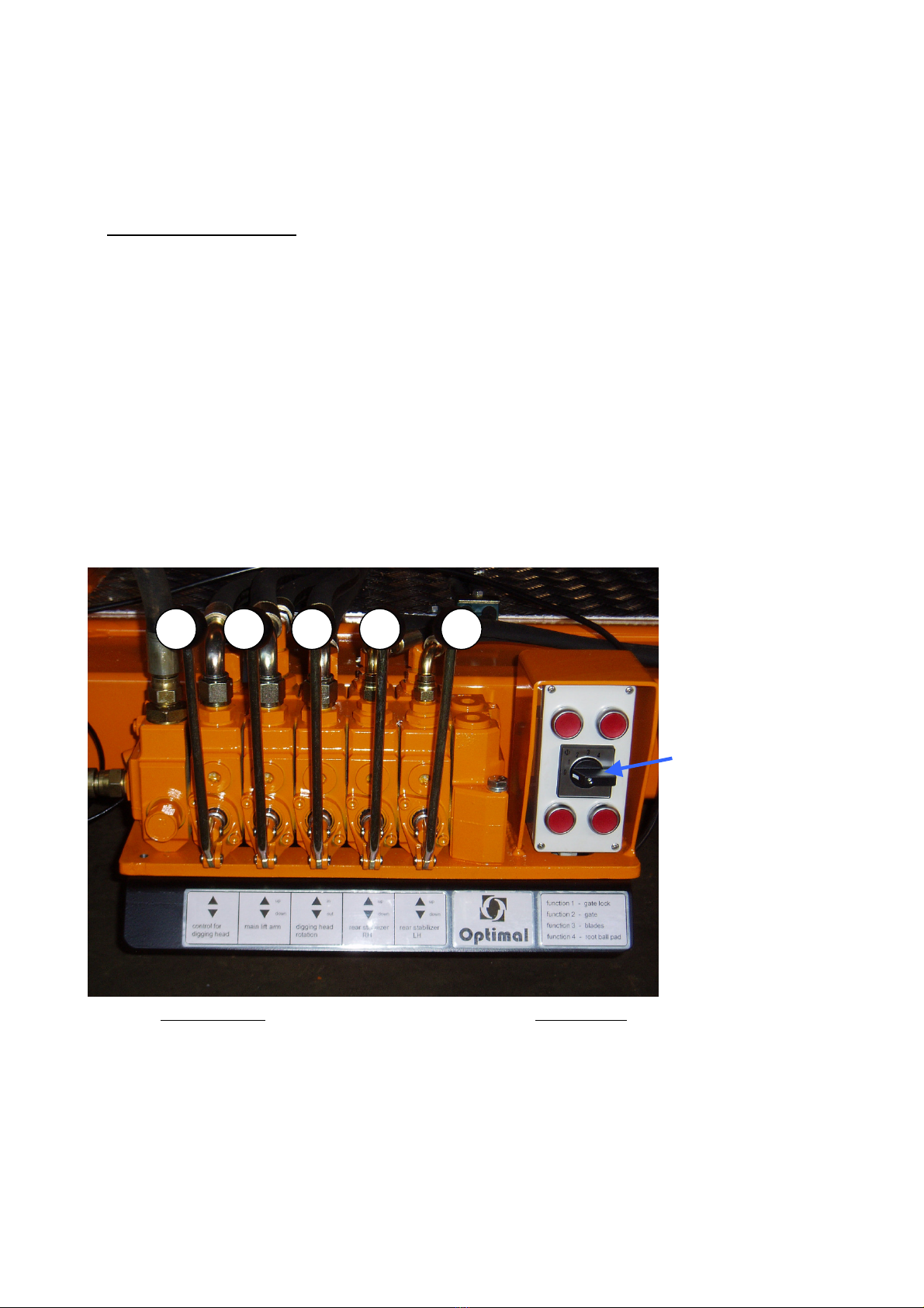
By means of control valve (2) lift arm ▼"down" the digging head is lowered fully until resting on the
ground. With control valve (3), digging head "rotate" ▲"in", ▼"out" the digging head frame is aligned
horizontally. Check again if the tree is in the center of the frame and correct, if necessary.
3.1.5 Now digging can commence:
control valve (1), rotary switch No. 3, alternatively push button S1-S4,
blades ▼"down".
For clean digging and to get the full depth of the root ball, the digging head must be kept
steady. This is achieved by working the blades crosswise, i.e. first two blades opposite to
each other are pressed for about 1/3 into the ground. Then the other two blades are pressed
into the ground. This crosswise digging is repeated until all four blades are completely in the
ground.
However, this digging depth of 1/3 is a rule of thumb only because the successive digging
process depends on the soil.
As soon as the digging head frame begins to lift, digging must be carried on with the other
two opposite blades.
3.1.6 Once all four blades have been fully pressed into the ground, the root ball pads are gently
pressed onto the root ball:
control valve (1), rotary switch No. 4, root ball presses ▼"down"
The root ball presses serve to hold the root ball together and keep it in shape.
3.1.7 Now the root ball together with the tree can be lifted out of the ground. First the rear
stabilizers must be extended. This is done as described under item 3.1.1.
3.1.8 The tree is in a vertical position and it is lifted with control valve
(2
). When the digging head is
above the base frame, it is rotated in until the tree is in a horizontal position:
control valve (3), digging head ▲"rotate in"
Lower lift arm until the digging head rests on the base frame:
control valve (2), lift arm ▼"down"
Now digging head and tree are in transport position.
3.1.9 Before the truck moves, both rear stabilizers must be retracted:
control valve (4) and (5) ▲"up"
IMPORTANT: When moving and working on public roads, the traffic rules
and regulations must be adhered to.!

- 8 -
4. Care and Maintenance
4.1 Blade Guides
The blades are furnished with plastic linings which slide on steel guides.
Once the plastic lining is worn to the point that the heads of the countersunk screws are flush
with the surface of the plastic linings, they must be replaced to prevent the screws
from damaging the guides.
IMPORTANT: Keep the guides clean.
4.2 No Lubrication
All sliding surfaces and bearings are made of plastic and do not require any lubrication.
4.3 Hydraulic Oil Supply
Check level of hydraulic oil regularly. For checking, retract all blades “up”
and lower the tree spade to the ground. If in that position the oil level is
below the mark of the sight glass, oil must be refilled.
4.4 Hydraulic Hoses
All hydraulic hoses must be inspected at least once per year. Damaged hoses
must be replaced. At least after 6 years all hoses must be replaced.
4.5 Cylinders
In case the tree spade is not getting used for two weeks, all piston rods of the hydraulic
cylinders must be cleaned and covered with a preserving oil film.
IMPORTANT: Tree spade must be lowered to the ground and switched
off when doing cleaning, maintenance or repair work !
Use original spare parts only !
The tree Spade must be inspected by an expert on
operational safety once per year !
Do not alter the design of the tree spade without having
consulted the manufacturer !

- 9 -
4.6 Adjusting Blades
Illustration 1 Illustration 2
1. General view of spade tower
2. A adjustment screw
B locking screw
C locking screw
3. Loosen locking screws B and C.
Move spade tower forward or
backward by means of adjustment
screw A
When blades are in desired position,
tighten locking nuts B and C.
Locking nut C must be tightened
with a torque of 420 Nm.
Illustration 3
C
B
A

- 10 -
4.7 Replacing Plastic Bush of Spade Cylinder
Illustration 4 Illustration 5
Unscrew bolts (D) and (E), remove worn bushes, insert new bushes (F) and (G).
D
E
F
G

- 11 -
4.8 Replacing Plastic Bush of Gate Cylinder
Illustration 6 Illustration 7
Illustration 8 Illustration 9

- 12 -
Illustration 10 Illustration 11
Illustration 12 Illustration 13

- 13 -
Illustr.6: General view of gate cylinder with piston rod and eye joint.
Illustr.7: Screw off plastic thread plug.
Illustr.8: Remove dowel pin by means of drift punch.
Illustr.9: Dowel pin has been removed. Note female thread on top of the pin,
Illustr.10: Place extractor on top of pin and fasten screw into female thread.
Illustr.11: When screw has a firm grip, hold it with wrench in position and tighten nut until
it is stopped by the extractor. Now hold nut and tighten screw further into
pin thread, thereby extracting the pin.
Illustr.12: Pin and plastic bush is removed from eye joint.
Illustr.13: The plastic bush is replaced.
Extractor with screw and nut.

- 14 -
5. Electro Hydraulic OPTIMAL 1100
control box
casing
electrical system - machine

- 15 -
6. Lubrication chart OPTIMAL 1100
6.1 Digging head

- 16 -
6.2 Superstructure

- 17 -
7. Trouble Shooting
1. Nothing moves. (none of the hydraulic functions works)
- Electricity supply to rotary switch is interrupted. Check fuses at power unit.
- Hydraulic disconnect is not properly attached. Check attachment.
2. Two hydraulic functions (e.g. gate lock and spades) work at the same time.
- On one of the valves the plunger does not move.
This defect might be caused by a dirt particle. Disassemble and clean the respective
valve.
- If this does not solve the problem, the valve is damaged and must be replaced.
3. After the blades have been retracted and the valve has been relieved, they immediately move
down again.
- If the spades move down a short way only, the oil supply of the pump might be too
high. Oil flow of power unit must be regulated by service of manufacturer.
- If the spades move down all the way, the seals in the spade cylinder might be defect
und must be replaced.
- If the spades move down all the way, the spade valve might be defect and must be
replaced.
4. The gate does not close and / or lock completely.
- The adjustment screw at the hinge wants readjustment.
Adjust adjustment screw.
- The eye joint is worn, bushes must be replaced.
5. Although the gate has been closed and locked properly, the blades do not move down.
- The safety switch at the lock needs readjustment.
- The electricity supply is interrupted. Check fuses at power unit.

- 18 -
6. The blades do not close properly although the spade cylinders are fully extended.
- Guides are worn and must be replaced.
- Blades are bent and have to be adjusted.
7. One function (any) does not work.
- The electricity supply is interrupted. Check power circuit.
- The magnet of the respective control valve is defect. Valve must be replaced.
- The plunger of the control valve is seized, probably due to a dirt particle in the
hydraulic oil. Disassemble valve and clean.
Trouble Shooting - individual spade control
8. The spades cannot be operated individually, i,e, all spades move at the same time.
- Controls were not switched to individual control. (When working in the individual
control mode, the red light must show red.)
- Circuit board is defect and must be replaced.
9. One of the blades moves even when not actuated.
- The electricity between valve and blade has been interrupted.
- Valve of the respective blade is defect. Replace valve.
10. None of the hydraulic functions works.
- Electricity supply to joy stick is interrupted. Check fuses at power unit.
- Hydraulic disconnect is not properly attached. Check attachment.
- Circuit board is defect and must be replaced.
Other manuals for 1100
1
This manual suits for next models
1
Table of contents
Popular Farm Equipment manuals by other brands

Unverferth
Unverferth BRENT V700 manual

Land Pride
Land Pride RBT6010 Operator's manual

Farmi Forest Corporation
Farmi Forest Corporation VALBY HF 231 OPERATION, MAINTENANCE AND SPARE PARTS MANUAL

Global
Global Corn Crusher Instructions for use

Wacker Neuson
Wacker Neuson GreenTec 1402 Handbook

GSI Group
GSI Group TopDry 2000 Series installation manual

Kubota
Kubota AP-SGR1566 Operator's manual

Wintex Agro
Wintex Agro WINTEX 1000 Workshop manual

breviglieri
breviglieri Hypermaster XL Operating and maintenance manual

Maschio
Maschio JUMBO RAPIDO Series Use and maintenance

Farm King
Farm King 1450 Operator and parts manual

Amazone
Amazone ZG-TS 5500 WAB operating manual