OPTIMUM Maschinen BF 30 Vario User manual

OPTIMUM
MASCHINEN - GERMANY
23. Oktober 2008 Page 1Add-on kit BF 46 / BF30 Vario CNC ; Version 1.0.2
©2008
GB
Modification instruction
Version 1.0.2
BF46 /BF 30 Vario CNC
Keep for future reference!
Fig.0-1: BF 46 Vario with CNC modification

OPTIMUM
MASCHINEN - GERMANY
23. Oktober 2008Page 2 Add-on kit BF 46 / BF30 Vario CNC ; Version 1.0.2
©2008 GB
Table of contents
1 Safety warnings (warning notes) ...........................................................................3
1.1 Classification of hazards......................................................................................................... 3
1.2 Proper use .............................................................................................................................. 4
1.3 Required auxiliary material...................................................................................................... 4
2 Packing list BF 30 Vario.........................................................................................5
3 Packliste BF 46 Vario.............................................................................................7
4 Assembly CNC kit..................................................................................................9
4.1 Assembly X-axis...................................................................................................................... 9
4.2 Assembly Y-axis.................................................................................................................... 13
4.3 Assembly Z-axis.................................................................................................................... 18
5 Assembly notes ...................................................................................................23
5.1 Assembly and disassembly of ball bearing spindles............................................................. 23
5.2 Maintenance instruction ball bearing spindle........................................................................ 24
6 Assembly ball bearing spindles ...........................................................................25
6.1 Disassembly of all axes......................................................................................................... 25
6.2 Assembly on the X- and Y-axis............................................................................................. 31
6.3 Assembly on the Z-axis......................................................................................................... 36
7 Installation of step motors....................................................................................39
7.1 Wiring X-, Y- and Z-axis........................................................................................................ 39
7.2 Plug assembly for X-, Y- and Z-axis...................................................................................... 41
8 Appendix..............................................................................................................43
8.1 Copyright............................................................................................................................... 43
8.2 Terminology/Glossary........................................................................................................... 43
8.3 Liability claims for defects / warranty .................................................................................... 44
8.4 Disposal ................................................................................................................................ 44
8.5 Product follow-up .................................................................................................................. 45

OPTIMUM
MASCHINEN - GERMANY
Safety warnings (warning notes)
23. Oktober 2008 Page 3Safety warnings (warning notes) Add-on kit BF 46 / BF30 Vario CNC ; Version 1.0.2
©2008
GB
1 Safety warnings (warning notes)
1.1 Classification of hazards
We classify the safety warnings into various levels. The table below gives an overview of the
classification of symbols (pictograms) and warnings for the specific danger and its (possible)
consequences.
1.1.1 Glossary of symbols
Pictogram Alarm
expression Definition/Consequences
DANGER! Imminent danger that will cause serious injury or death to
personnel.
WARNING! Risk: A danger that might cause serious injury or death to
personnel.
CAUTION! Danger of unsafe procedure that might cause injury to
personnel or damage to property.
ATTENTION!
Situation that could cause damage to the machine and
product and other types of damage.
No risk of injury to personnel.
INFORMATION
Application tips and other important or useful information
and notes.
No dangerous or harmful consequences for personnel or
objects.
In the case of specific dangers, we replace the pictogram by
or
General
danger with a warning
of injuries to
hands, hazardous
electrical
voltage,
rotating parts.
gives additional advices
enumerations

Safety warnings (warning notes)
OPTIMUM
MASCHINEN - GERMANY
23. Oktober 2008Page 4 Safety warnings (warning notes) Add-on kit BF 46 / BF30 Vario CNC ; Version 1.0.2
©2008 GB
1.2 Proper use
WARNING!
In the event of improper use of the add-on pieces, it
• will endanger the user,
• will endanger the machine and other material property of the operator or user,
• may affect proper operation of the machine.
The add-on pieces as conversion kit are provided for motor-driven milling operations of your
machine.
Improper
use! The milling machine with the adapter kit must only be placed and operated in dry and ventilated
rooms.
The handwheels of the driven axes need to be disassembled.
If the adapter kit is used in any way other than described above or modified without approval of
the company Optimum Maschinen Germany GmbH the adapter kit is no longer properly used.
We do not take any liability for damages caused by improper use.
We would like to stress that any modifications to the construction, or technical or technological
modifications that have not been authorized by Optimum Maschinen GmbH will also render the
guarantee null and void.
We are pleased that you have decided to buy a CNC milling machine made by Optimum Maschi-
nen Germany GmbH.
The illustrations of the machines may vary in a few details from the illustrations of this instruction
manual, but this will have no effect on the operation of the machine.
Any changes in the construction, equipment and accessory are reserved for the advancement.
Therefore, you cannot derive any claims from the indications and descriptions. Errors are
reserved!
1.3 Required auxiliary material
Means of shaft lock-down device "Loctite 648, join the shaft".
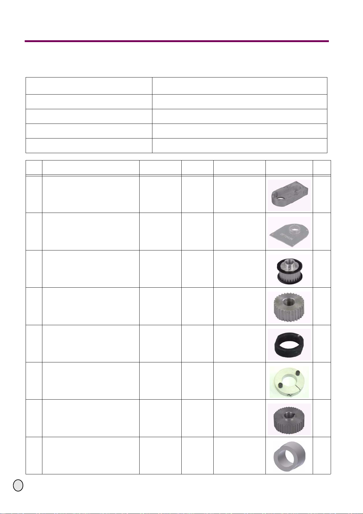
The designation of the parts in the assembly description corresponds to the numbering on
the packing list.
In order to degrease the shaft, a cleaner for brakes or a corresponding cleaning agent is
required.
Required tools:
Hand drill, caliper gauge,
Twist drill 6.8mm, screw tap M8, countersink
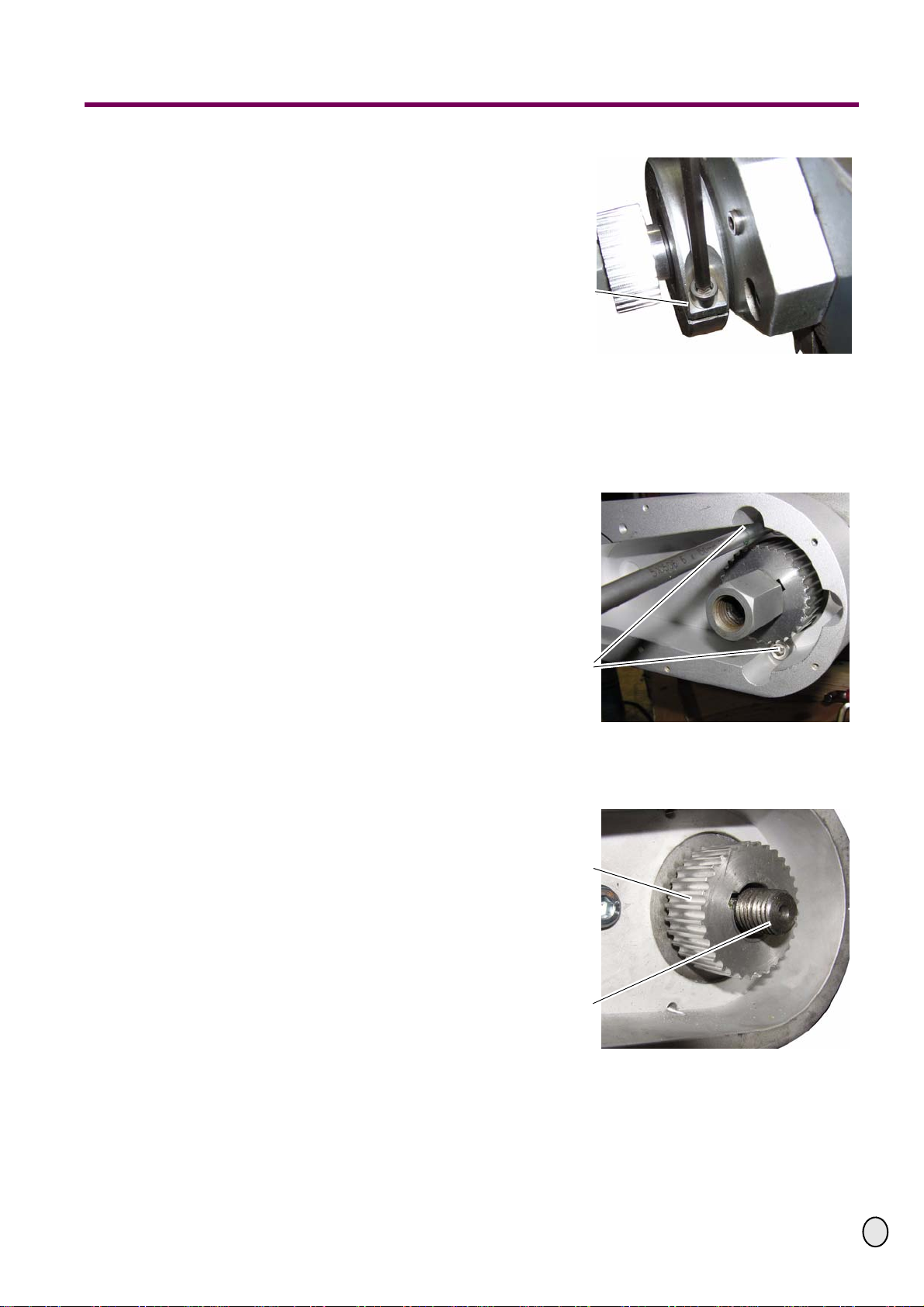
Allen key, fork wrench, socket wrench 24mm
Screw driver, tongs
Wire cutter, trimming knife
Hot-air drier, shrink hose, sleeves
Blow-back proof plastic tip hammer
Lubricating oil for thread cutting

OPTIMUM
MASCHINEN - GERMANY
Packing list BF 30 Vario
23. Oktober 2008 Page 5Packing list BF 30 Vario Add-on kit BF 46 / BF30 Vario CNC ; Version 1.0
©2008
GB
2 Packing list BF 30 Vario
Bezeichnung
Designation CNC - Anbausatz MK F30DP
BF 30 CNC
Artikelnummer Anbausatz
Item no. mounting set 3570030
Netto Gewicht
Net Weight 6.3 kg
Brutto Gewicht
Cross Weight 7 kg
Abmessung (Lx B x H)
Dimension (L x W x H) 320 mm x 285 mm x 80 mm
Nr.
No Bezeichnung
Description Artikelnummer
Article no. Teile Nr.
Part no. Grösse
Size Abbildung
Picture
Stck.
Qty.
1Gehäuse für X-, Y- und Z-Achse
Drive housing for X-, Y- and Z-axis 0 3570046 01 BFCNC-01 3
2Gehäusedeckel für X-, Y- und Z-Achse
Housingcover for X-, Y- and Z-axis 0 3570046 02 BFCNC-02 3
3
Zahnriemenscheibe für Motor an
X-, Y- und Z-Achse
Toothed belt disk for motor
on the X-,Y- and Z-axis
0 3570046 03 BFCNC-03 22 teeth
HTD-22-5M-15-AS 3
4
Zahnriemenscheibe für Welle an
Y- und Z-Achse
Toothed belt disk for the shaft on the Y- and
Z-axis
0 3570030 04 BF3CNC-04 32 teeth
HTD-32-5M-15-AS 2
5Mutter für Y- und Z-Achse
Nut for Y- and Z-axis 0 3570030 07 BF3CNC-05 2
6Distanzring X-Achse
Distance ring for the X-axis 0 3570030 10 BF3CNC-06 1
7Zahnriemenscheibe für Welle X-Achse
Toothed belt disk for shaft at X-axis 0 3570030 11 BF3CNC-07 32 teeth
HTD-32-5M-15-AS 1
8Hülse für Handrad X- und Y-Achse
Bushing for the handwheel on the X- and Y-
axis 0 3570030 08 BF3CNC-08 2

Packing list BF 30 Vario
OPTIMUM
MASCHINEN - GERMANY
23. Oktober 2008Page 6 Packing list BF 30 Vario Add-on kit BF 46 / BF30 Vario CNC ; Version 1.0
©2008 GB
9Schrittmotor für X-, Y- und Z-Achse
Step motor for X-, Y- and Z-axis 3590012 34 H2120-0.1A
8 Nm 3
10 Zahnriemen für X-, Y- und Z-Achse
Toothed belt for X-, Y- and Z-axis 0 3570046 14 BFCNC-14 HTD-360-5M-15 3
11 Schraube
Screw "DIN 4762" M8x15 6
12 Madenschraube
Screw DIN 914 M4x4 3
13 Schraube
Screw DIN 4762 M5x20 14
14 Schraube
Screw DIN 4762 M6x25 1
15 Schraube
Screw DIN 4762 M3x10 11
16 Schraube
Screw DIN 4762 M8x15 2
17 Schraube
Screw DIN 4762 M8x40 2
18 Kabel
Wire cord -4 x 0,75mm215m
Nr.
No Bezeichnung
Description Artikelnummer
Article no. Teile Nr.
Part no. Grösse
Size Abbildung
Picture
Stck.
Qty.
Prüfer:
Verified by: Datum:
Date:

OPTIMUM
MASCHINEN - GERMANY
Packliste BF 46 Vario
23. Oktober 2008 Seite 7Packliste BF 46 Vario Anbausatz BF 46 / BF30 Vario CNC ; Version 1.0
©2008
GB
3 Packliste BF 46 Vario
Bezeichnung
Designation CNC - Anbausatz MK F46DP
BF 46 CNC
Artikelnummer Anbausatz
Item no. mounting set 3570046
Netto Gewicht
Net Weight 6,3 kg
Brutto Gewicht
Cross Weight 7 kg
Abmessung (Lx B x H)
Dimension (L x W x H) 320 mm x 285 mm x 80 mm
Nr.
No Bezeichnung
Description Artikelnummer
Article no. Teile Nr.
Part no. Grösse
Size Abbildung
Picture
Stck.
Qty.
1Gehäuse für X-, Y- und Z-Achse
Driver house for X.Y and Z-axis 0 3570046 01 BFCNC-01 3
2Gehäusedeckel für X-, Y- und Z-Achse
Housingcover for X,Y and Z axis 0 3570046 02 BFCNC-02 3
3Zahnriemenscheibe für Motor
an X-, Y- und Z-Achse
Toothed belt disk for Motor X-,Y- and Z-axis 0 3570046 03 BFCNC-03 22 Zähne
HTD-22-5M-15-AS 3
4Zahnriemenscheibe für Welle an Y- und
Z-Achse
Toothed belt disk for Shaft Y- and Z-axis 0 3570046 04 BFCNC-04 32 Zähne
HTD-32-5M-15-AS 2
5Mutter für Y- und Z-Achse
Nut for Y- and Z-axis 0 3570046 07 BFCNC-07 2
6Distanzring X-Achse
Distanzring for X-axis 0 3570046 10 BFCNC-10 1
7Zahnriemenscheibe für Welle X-Achse
Toothed belt disk for shaft X-axis 0 3570046 11 BFCNC-11 32 Zähne
HTD-32-5M-15-AS 1
8Hülse für Handrad an X- und Y-Achse
Distanz for Handwheel x and y Axis 0 3570046 12 BFCNC-12 2

Packliste BF 46 Vario
OPTIMUM
MASCHINEN - GERMANY
23. Oktober 2008Seite 8 Packliste BF 46 Vario Anbausatz BF 46 / BF30 Vario CNC ; Version 1.0
©2008 GB
9Schrittmotor für X-, Y- und Z-Achse
Step motor for X-, Y- and Z-axis 357 3314 34 H2160-02IP
12 Nm 3
10 Zahnriemen für X-, Y-, und Z-Achse
Toothed belt for X-, Y- and Z-axis 0 3570046 14 BFCNC-14 HTD-360-5M-15 3
11 Schraube
Screw "DIN 4762" M8x15 6
12 Madenschraube
Screw DIN 914 M4x4 3
13 Schraube
Screw DIN 4762 M5x20 14
14 Schraube
Screw DIN 4762 M3x10 11
15 Schraube
Screw DIN 4762 M8x15 2
16 Schraube
Screw DIN 4762 M8x40 2
17 Mutter
Nut DIN 985 M16 3
18 Unterlegscheibe
Washer DIN 125-2 B 17 3
19 Kabel
Wire cord -4 x 0,75mm215m
Nr.
No Bezeichnung
Description Artikelnummer
Article no. Teile Nr.
Part no. Grösse
Size Abbildung
Picture
Stck.
Qty.
Prüfer:
Verified by: Datum:
Date:

OPTIMUM
MASCHINEN - GERMANY
Assembly CNC kit
23. Oktober 2008 Page 9Assembly CNC kit Add-on kit BF 46 / BF30 Vario CNC ; Version 1.0.2
©2008
GB
4 Assembly CNC kit
CNC conversion kit
4.1 Assembly X-axis
4.1.1 Disassemble the self-locking nut and
the shim of the left handwheel of the X-
axis.
4.1.2 Remove the handwheel with a blow-
back proof plastic tip hammer with
smooth knocks. Turn the handwheel at
the same time.
Fig.4-1: Handwheel on the left
4.1.3 Remove the dimension arrow head of
the X-axis with tongs.
Fig.4-2: Remove the dimension arrow head
4.1.4 Unscrew the three fixing screws of the
plate on the X-axis.
Fig.4-3: Unscrew screws
Unscrew the
handwheel of the X-
axis
Dimension arrow
head
Fixing screws

Assembly CNC kit
OPTIMUM
MASCHINEN - GERMANY
23. Oktober 2008Page 10 Assembly CNC kit Add-on kit BF 46 / BF30 Vario CNC ; Version 1.0.2
©2008 GB
4.1.5 Fix the distance ring (No 6) on the plate
of the X-axis.
Fig.4-4: Screw the distance ring
4.1.6 Screw the housing (Nr. 1) on the
distance ring.
Fig.4-5: Screw housing
4.1.7 Slide the pulley (No 7) on the shaft of
the X-axis.
Fig.4-6: Assemble the pulley
Distance ring
Screw housing
Pulley
Shaft X-axis

OPTIMUM
MASCHINEN - GERMANY
Assembly CNC kit
23. Oktober 2008 Page 11Assembly CNC kit Add-on kit BF 46 / BF30 Vario CNC ; Version 1.0.2
©2008
GB
4.1.8 Screw the nut on the shaft (beforehand
apply some Loctite).
Slightly hold on the handwheel at the
right side and slightly tighten the hexa-
gon nut using a fork wrench.
Fig.4-7: Screw the nut
4.1.9 Put the toothed belt (No 10) on the pul-
ley.
Determine the distance between the top
edge of the housing and the top of the
pulley using a caliper gauge
(about 6 mm to 8 mm).
Fig.4-8: Attach the toothed belt
4.1.10 Mount the pulley (No 3) on the step-
ping motor (beforehand apply some
Loctite to the motor shaft). Mount the
pulley in a way that the end is aligned
with the shaft of the motor.
Then tighten the pulley using a head-
less screw.
Fig.4-9: Mount the pulley of the motor
Hexagon nut
Fork wrench
Toothed belt
Pulley edge
Plane surface of the
motor

Assembly CNC kit
OPTIMUM
MASCHINEN - GERMANY
23. Oktober 2008Page 12 Assembly CNC kit Add-on kit BF 46 / BF30 Vario CNC ; Version 1.0.2
©2008 GB
4.1.11 Attach the motor on the housing.
Fig.4-10: Attach the motor
4.1.12 Fix the motor on the housing using the
four screws. It is recommended to
screw the motor in a way that the outlet
of the cables shows to the rear.
Fig.4-11: Screw the motor
4.1.13 Fix the cover (No 2) to the housing by
using the four screws.
Fig.4-12: Screw the cover
Motor
Cable outlet
Motor
Cover

OPTIMUM
MASCHINEN - GERMANY
Assembly CNC kit
23. Oktober 2008 Page 13Assembly CNC kit Add-on kit BF 46 / BF30 Vario CNC ; Version 1.0.2
©2008
GB
4.1.14 Detach the right handwheel of the X-
axis and plug the bushing (No 8) on the
X-axis.
Fig.4-13: Mount the bushing
4.1.15 Mount the bushing (No 9) on the shaft
of the X-axis and then screw the nut. In
doing so, adjust the spindle clearance
at the same time.
To do so, you need to hold the bushing
tight with the spanner flat.
Fasten the nut until you determine that
the spindle nut is properly closed to the
flanks of the spindle thread.
By minimum varying of the position of
the nut, you can adjust the pretension
and the thread clearance.
Fig.4-14: Mount the bushing
4.2 Assembly Y-axis
4.2.1 Hold the hexagon nut of the Y-axis tight
with the fork wrench and detach the
hexagon socket screw. Unscrew the
hexagon bolt.
4.2.2 Remove the handwheel using a blow-
back proof plastic tip hammer with
slight strokes. In doing so, turn the
handwheel.
Fig.4-15: Loosen the handwheel
Bushing
X-axis
Fork wrench
Hexagon nut
Loosen the
handwheel of the Y-
axis

Assembly CNC kit
OPTIMUM
MASCHINEN - GERMANY
23. Oktober 2008Page 14 Assembly CNC kit Add-on kit BF 46 / BF30 Vario CNC ; Version 1.0.2
©2008 GB
4.2.3 Disassemble the cover at the rear side
of the Y-axis.
Fig.4-16: Disassemble the cover
4.2.4 Unscrew the three screws from the
plate. Pull off the plate.
Fig.4-17: Disassemble the screws
4.2.5 If the fixing holes are not available,
please perform the working steps des-
cribed under the items 4.2.5 and 4.2.6.
Put the housing of the X-axis No 1 on
the plate and align it.
Mark out the holes using a felt pen.
Remove the housing and punch-mark
the hole using a center punch.
Fig.4-18: Mark out the holes
Cover
Unscrew
the screws from the
plate
Drawn holes
Housing

OPTIMUM
MASCHINEN - GERMANY
Assembly CNC kit
23. Oktober 2008 Page 15Assembly CNC kit Add-on kit BF 46 / BF30 Vario CNC ; Version 1.0.2
©2008
GB
4.2.6 Drill the three core holes for M8 at the
marked positions in the plate using an
appropriate drill. Then deburr the drills
using a countersink. Finally cut the
thread M8 and screw the plate onto the
machine.
Fig.4-19: Drilling
4.2.7 Screw the nut (No 5) on the shaft of the
Y-axis (beforehand degrease the shaft
using a cleaning agent).
Screw and tighten the pulley (No 4)
onto the Y-axis using a shaft-securing
mean.
Fig.4-20: Tighten the drive pinion
4.2.8 Screw the housing (No 1) using the
three hexagon socket screws.
Determine the clearance between the
housing edge and the pulley top side
using a caliper gauge
(about 6 mm to 8 mm).
Fig.4-21: Mount the housing
Drill
Plate
Pulley
Fixing screws

Assembly CNC kit
OPTIMUM
MASCHINEN - GERMANY
23. Oktober 2008Page 16 Assembly CNC kit Add-on kit BF 46 / BF30 Vario CNC ; Version 1.0.2
©2008 GB
4.2.9 Put the pulley (No 3) on the motor shaft
(beforehand apply some Loctite on the
motor shaft).
Mount the pulley shaft aligned with the
shaft end of the motor. After setting the
pulley, tighten it using the headless
screws.
Fig.4-22: Mount the pulley
4.2.10 Attach the toothed belt on the toothed
belt disk in the housing (as illustrated).
Fig.4-23: Mount the belt
4.2.11 Insert the motor (No 9) into the housing.
Fig.4-24: Attach the motor
Pulley
Motor surface
Pulley edge
Belt
Housing
Motor

OPTIMUM
MASCHINEN - GERMANY
Assembly CNC kit
23. Oktober 2008 Page 17Assembly CNC kit Add-on kit BF 46 / BF30 Vario CNC ; Version 1.0.2
©2008
GB
4.2.12 Screw the step motor to the housing
using the four hexagon socket screws.
Fig.4-25: Screw the motor
4.2.13 Screw the lid of the housing (No 2) to
the housing using the hexagon socket
screws.
Fig.4-26: Screw the cover of the housing
4.2.14 Mount the bushing (No 9) on the shaft
of the Y-axis and then screw the nut. In
doing so, you simultaneously adjust the
spindle clearance.
To do so, you need to hold the bushing
tight with the spanner flat.
Fasten the nut until you determine if the
spindle nut is properly closed to the
flanks of the spindle thread.
By minimum varying of the position of
the nut, you can adjust the pretension
and the thread clearance.
Fig.4-27: Mount the bushing.
Hexagon socket
screw
Motor
Hexagon socket
screw
Cover
Bushing

Assembly CNC kit
OPTIMUM
MASCHINEN - GERMANY
23. Oktober 2008Page 18 Assembly CNC kit Add-on kit BF 46 / BF30 Vario CNC ; Version 1.0.2
©2008 GB
4.3 Assembly Z-axis
4.3.1 Remove the three screws of the spindle
cover of the Z-axis and take off the
cover.
Fig.4-28: Remove spindle cover
4.3.2 If the holes are not yet available, please
perform the working steps described
under the items 3.3.2 and 3.3.3.
Put the housing (No 1) on the plate of
the Z-axis and mark out the holes in the
same way as for the Y-axis.
Remove the four hexagon socket
screws of the plate and remove the
plate.
Fig.4-29: Remove the plate
4.3.3 Drill the three core holes for M8 into the
plate at the marked out positions using
an appropriate drill. Then deburr the
drills using a countersink. Finally cut the
thread M8 and remount the plate of the
Z-axis.
Fig.4-30: Drilling
Spindle cover
Z-axis
The plate of the Z-
axis
Drill
Plate

OPTIMUM
MASCHINEN - GERMANY
Assembly CNC kit
23. Oktober 2008 Page 19Assembly CNC kit Add-on kit BF 46 / BF30 Vario CNC ; Version 1.0.2
©2008
GB
4.3.4 Mount the pulley (No 4) on the shaft of
the Z-axis (beforehand apply some Loc-
tite on the motor shaft) and lock it with
the nut (No 5). Determine the clea-
rance between the edge of the housing
and the top edge of the pulley using a
caliper gauge (about 6 mm to 8 mm).
Fig.4-31: Mount shaft of the pulley
4.3.5 Mount the housing (No 1) using the
three screws M8.
Fig.4-32: Mount the housing
4.3.6 Put the pulley (No 3) on the motor shaft
(beforehand apply some Loctite on the
motor shaft). Mount the pulley shaft ali-
gned with the shaft end of the motor.
After setting the pulley disk, tighten the
headless screws.
Fig.4-33: Mount the pulley
Pulley
Housing
Pulley
Motor surface
Pulley edge

Assembly CNC kit
OPTIMUM
MASCHINEN - GERMANY
23. Oktober 2008Page 20 Assembly CNC kit Add-on kit BF 46 / BF30 Vario CNC ; Version 1.0.2
©2008 GB
4.3.7 Put the belt on the pulley in the hou-
sing.
Fig.4-34: Attach the belt
4.3.8 Attach the motor (No 9) to the housing.
Fig.4-35: Attach the motor
4.3.9 Fix the motor on the housing using the
four hexagon socket screws.
Fig.4-36: Screw the motor
Belt
Motor
Motor
This manual suits for next models
1
Table of contents