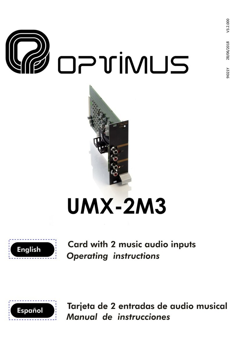
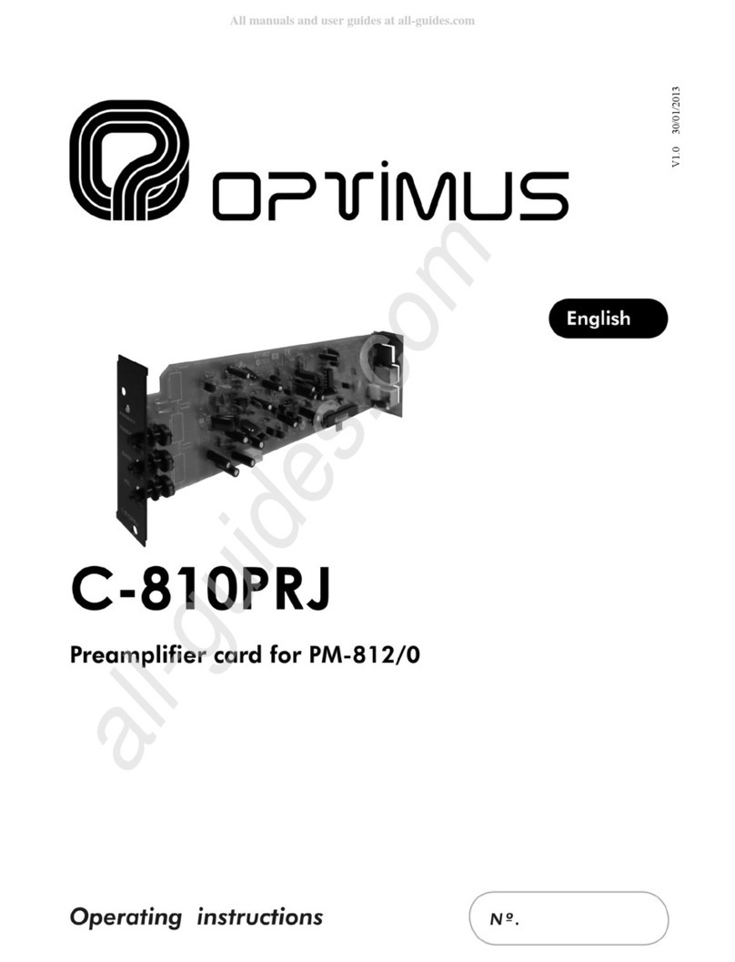
Optimus UMX-TEL User manual

UMX-TEL version 4.3.000AS
1
UMX-TEL
(ASIA VERSION)
DTMF Telephone interface card
for UMX-03/0 audio matrix
9I021T 21/06/2019 V4.3.000AS


UMX-TEL version 4.3.000AS
3
UMX-TEL
(ASIA VERSION)
DTMF Telephone interface card
for UMX-03/0 audio matrix
Table of contents
1. GENERAL INFORMATION .......................................................................................................................................................5
2. ELEMENTS5
3. CONFIGURATION OF THE SYSTEM..........................................................................................................................................5
3.1. CONFIGURATION OF THE CARD.....................................................................................................................................6
3.1.1. SENDING CONFIGURATIONS ..............................................................................................................................6
3.2. CONFIGURATION OF THE CALL......................................................................................................................................7
3.2.1. CONFIGURATION PARAMETERS .........................................................................................................................7
3.2.2. FACTORY CONFIGURATION ................................................................................................................................ 9
3.2.3. CALL CONFIGURATION PROCESS......................................................................................................................10
4. OPERATION .........................................................................................................................................................................10
4.1. BROADCAST OF A MESSAGE WITHOUT A PASSWORD ................................................................................................10
4.2. BROADCAST OF A MESSAGE WITH A PASSWORD .......................................................................................................10
4.3. CONFIGURATION EXAMPLE AND SENDING AN ANNOUNCEMENT..............................................................................11
5. INSERTING THE CARD .......................................................................................................................................................... 12
6. TECHNICAL SPECIFICATIONS ................................................................................................................................................13
7. SOFTWARE AND FIRMWARE VERSIONS ............................................................................................................................... 13
8. DOCUMENT VERSION TRACKING ......................................................................................................................................... 13
9. GUARANTEE ........................................................................................................................................................................ 14
WARNING. This is a Class A unit. In a domestic environment this unit may cause radio interferences. In this case the user
must take the necessary precautions.


UMX-TEL version 4.3.000AS
5
UMX-TEL
(ASIA VERSION)
DTMF Telephone interface card
for UMX-03/0 audio matrix
1. GENERAL INFORMATION
The UMX-TEL model of the DTMF telephone interface provides access to any public
address zone or group from the telephony installation.
It occupies a card slot in the UMX-03/0 modular chassis. If the UMX-03/0 audio
matrix has any card configured with micro sensitivity, 2 slots must be left between
these cards and the UMX-TEL card.
2. ELEMENTS
1) Audio level adjustment of the telephone card.
2) PHONE LINE IN: RJ-11 connector. Telephone line connection.
3) CONFIG. LED
•
Slow blink: Card in standby mode (READY).
•
Fast blink: Starts to blink when the CONFIG. button is pressed. This
indicates that the card is in configuration mode. Once the card answers,
the LED remains permanently lit.
•
Permanently lit: This indicates that the card is broadcasting a message or
the configuration parameters are being entered.
4) CONFIG. button. This is used to configure the parameters of the card.
3. CONFIGURATION OF THE SYSTEM
Once it has been inserted in the chassis, the UMX-TEL card must be configured before it is used.
The UMX-TEL card has two distinct types of configuration:
The first configuration, which we will call Configuration of the card, assigns the basic parameters for the operation of the card in the
PA system: Name of the card, input number, etc. (see section 3.1).
The other configuration, which we will call Configuration of the call, defines the mode in which we communicate with the card by
means of the DTMF tones of a telephone call. Access to this configuration is gained by pressing the “CONFIG.” button on the rear of
the card (see section 3.2).
Figure 1
ESSENTIAL
The telephone connection must be made with an analog exchange extension
or an analog outside line.
The dialling system must use DTMF tones.

UMX-TEL version 4.3.000AS
6
UMX-TEL
(ASIA VERSION)
DTMF Telephone interface card
for UMX-03/0 audio matrix
3.1. CONFIGURATION OF THE CARD
The parameters of the card can be configured by using a PC connected
to the UMX-03/0, using the P.A. Manager software.
1. Open the application from the server PC.
2. On the installations screen, edit or add a UMX-TEL card and
configure the parameters of the input.
•
Slot. This is the position occupied by the card on the UMX-03/0
(looking at a UMX-03/0 from the rear, slot 1 is the one on the
right and slot 10 the one on the left). On a UMX-03/0 each card
must be in a different slot.
•
Enabled input. This control enables or disables the input.
•
Name. Name of the input. Maximum of 20 characters.
•
Input Number. Also known as Logical Input. Using the numeric
keyboard, enter a number between 1 and 9999. This number will
be the one that identifies this input on the various menus of the
UMX-03/0. There cannot be more than one input with the same
number.
•
Audio Source. The audio source you select will have an assigned
mode (priority with respect to the rest of the system's sound
sources). This will be the mode assigned to the UMX-TEL card.
•
Asoc. Outputs. Configure this option if Fixed option has been
selected in the Selection mode.
•
Selection Mode. Indicates the kind of destination to which the
message will be sent:
-When Zones are selected, the card will send the message to
the selected zone by DTMF dialling.
-When Groups are selected, the card will send the message
to the selected group by DTMF dialling (the groups must be
created beforehand by means of the P.A. Manager
software).
-When Fixed is selected, the card will send the message to
predefined zones or groups without necessity to select these
zones by means of dialing.
These predefined zones are configured by the Asoc. Outputs
field.
In order to introduce the associated outputs, click on the
.... button and select the zones and groups from the list.
For multiple selection, keep pressing the Ctrl. key while
making the selection.
To finalize, click on Accept.
3. Once the parameters have been configured, click on Accept.
3.1.1. SENDING CONFIGURATIONS
To complete programming from the software, once the equipment unit has been configured, three operations are required:
1. Connect equipment: On the installation tree, right click with the mouse on the UMX-03/0 and select Connect.
2. Save the installation: Open the File menu and select Save.
3. Send configurations: On the installation tree, right click with the mouse on the UMX-03/0 whose configuration has changed
and select Send configurations.

UMX-TEL version 4.3.000AS
7
UMX-TEL
(ASIA VERSION)
DTMF Telephone interface card
for UMX-03/0 audio matrix
3.2.CONFIGURATION OF THE CALL
This defines the mode in which we communicate with the card by means of the DTMF tones of the telephone call. Access to this
configuration is gained by pressing the rear “CONFIG.” button and making a call through the telephone connection. Once the card
answers, 10 digits must be entered. Each digit configures a different parameter.
3.2.1. CONFIGURATION PARAMETERS
The programmable parameters are:
Digit / Parameter Description Values
1 First digit of the password 0 to 9
2 Second digit of the password 0 to 9
3 Third digit of the password 0 to 9
4 Number of call tones before card answers 1 to 9
5 Debug mode 0 to 3
6 Number of digits for calling zones or groups, or fix call 0 to 4
7 Detection time of DTMF “1” hanging up tone 0 to 9
8 Hanging up tone detection time 0 to 9
9 Noise gate (0: deactivated / 1: activated) 0 to 1
10 Maximum message time 0 to 9
•PARAMETERS 1, 2 and 3: PASSWORD
These establish the three digits of the password:
P1 P2 P3 DESCRIPTION
0 0 0 Without password: the call is made and the card answers after the dialling tones configured.
X X X The password is X X X: the call is made, the card answers and the password must be keyed in from the
telephone.
•PARAMETER 4: CALL TONES
This configures the number of tones after which the card will answer when a call is made to broadcast a message (between 1 and
9).
NB: In the case of the configuration call, the card always answers after two call tones.
•PARAMETER 5: DEBUG MODE.
Set this parameter to 0(debug mode OFF).

UMX-TEL version 4.3.000AS
8
UMX-TEL
(ASIA VERSION)
DTMF Telephone interface card
for UMX-03/0 audio matrix
•PARAMETER 6: NUMBER OF DIGITS FOR CALLING ZONES OR GROUPS
This defines the number of digits that must be entered to call a zone or group (maximum 3 digits / 999 zones-groups), or establish
that the call will be to previously defined fix zones.
P 6 NUMBER OF DIGITS FOR CALLING ZONES OR GROUPS
0 0 Digits. No need to select zones when paging. The messages destination is always the same (zones or groups
previously defined when configuring the card).
1 1 Digit. Allows to call 9 different zones or groups (from 1 to 9).
2 2 Digits. Allows to call 99 different zones or groups (from 01 to 99).
3 3 Digits. Allows to call 999 different zones or groups (from 001 to 999).
4 4 Digits. Allows to call 9999 different zones or groups (from 0001 to 9999).
•PARAMETER 7: DETECTION TIME OF DTMF “1” HANGING UP TONE
Admits values from 0 to 9. Increases the detection time of the DTMF hanging up tone by steps of 30 ms. (hanging up functionality
by pressing 1). 0 = disabled, 1 = 90 ms … 9 = 330 ms).
P 7 DETECTION TIME OF DTMF “1” HANGING UP TONE
0 Hang up by pressing 1 deactivated
1 90 milliseconds
2 120 milliseconds
3 150 milliseconds
4 180 milliseconds
5 210 milliseconds
6 240 milliseconds
7 270 milliseconds
8 300 milliseconds
9 330 milliseconds
•PARAMETER 8: HANGING UP TONE DETECTION TIME
According to the telephone central type or telephone line quality the card may interpret some voice tone as hanging up tone. If this
occurs, increase this parameter by fixing a longer detection time.
Admits values from 0 to 9 (see the P8 table).
IMPORTANT: if 0 is assigned to this parameter, the automatic hanging up function is deactivated; in this case, if telephone is
hanged up and communication time is not finished (parameter 10), the hanging up tone will be reproduced in the public
address system until this time finishes.
To avoid this, the system includes the hanging up forcing functionality, by pressing “1”. By pressing the “1” key, the telephone
is hanged up, independently from the assigned values to parameter 8 (hanging up tone detection time) and to parameter 10
(communication time).

UMX-TEL version 4.3.000AS
9
UMX-TEL
(ASIA VERSION)
DTMF Telephone interface card
for UMX-03/0 audio matrix
P 8 HANGING UP TONE DETECTION TIME
0 Disabled
1 100 milliseconds
2 225 milliseconds
3 300 milliseconds
4 350 milliseconds
5 500 milliseconds
6 650 milliseconds
7 800 milliseconds
8 1000 milliseconds
9 1200 milliseconds
•PARAMETER 9: NOISE GATE
Through this parameter, the noise gate available on this telephone interface can be activated (dial 1) or deactivated (dial 0).
•PARAMETER 10: COMMUNICATION TIME
This determines the maximum communication time. Once this time has elapsed, the card will hang up automatically.
P10 MAXIMUM COMMUNICATION TIME
0 8 seconds
1 16 seconds
2 30 seconds
3 45 seconds
4 60 seconds
5 75 seconds
6 90 seconds
7 105 seconds
8 120 seconds
9 900 seconds (15 minutes)
3.2.2. FACTORY CONFIGURATION
The card will be factory configured as follows:
0 0 0 2 0 0 2 4 0 2
Without password
Answer
after 2 call
tone
Debug
mode OFF
Without zones
selection. The
messages
destination is
the zones or
groups
previously
defined when
configuring the
card.
Hanging up
tone
duration for
DTMF “1”
detection
(hanging up
pressing 1):
120ms
Hanging up
tone
detection:
350ms
Noise gate
deactivated
Communication
time: 30 s.

UMX-TEL version 4.3.000AS
10
UMX-TEL
(ASIA VERSION)
DTMF Telephone interface card
for UMX-03/0 audio matrix
3.2.3. CALL CONFIGURATION PROCESS
To change the parameters, it is necessary to make a configuration call as described below:
1. Press the rear button CONFIG. The CONFIG. LED will start to blink quickly. The user has approximately 60 seconds to make the
call and send the configuration parameters.
2. Dial the telephone number (or extension) corresponding to the UMX-TEL telephone adaptor from a tone dial telephone. The
unit will answer on the second call tone, the CONFIG. LED will remain lit and three different tones will be heard through the
telephone receiver.
3. Key in the 10 digits corresponding to the 10 configuration parameters. 3 identical tones will be heard through the telephone
receiver to confirm reception of the configuration and the CONFIG. LED changes to READY mode (slow blink).
4. Hang up the telephone.
4. OPERATION
Once the card has been configured by following the steps described in the previous sections, access can be gained to the PA system
from the telephone by dialling the number corresponding to the telephone line connected to the card.
4.1.BROADCAST OF A MESSAGE WITHOUT A PASSWORD
1. Pick up the telephone.
2. Dial the telephone number corresponding to the card.
3. Wait for the card to answer after the established call tones (from 1 to 9 depending on the configuration).
4. The card answers and emits a series of short tones.
5. If the card is configured with selection of zones or groups, enter the digits of the zone (or group) where it is wished to
broadcast the message.
If no number is entered in 9 seconds, the card emits short tones and then hangs up.
If the zone entered is busy due to an announcement of higher priority, busy tones will be heard and the card will hang up. The
same will occur if the destination unit is a group and all the zones in the group are busy. If the group has free zones and busy
zones, the calling process continues.
6. Once the zone (or group) number has been entered, a long tone will be heard, indicating that the message can now be
broadcast. At the end of the message, hang up the telephone or press “1”. By default, the system will hang up automatically
once the communication time defined when the card is configured has elapsed.
4.2.BROADCAST OF A MESSAGE WITH A PASSWORD
1. Pick up the telephone.
2. Dial the telephone number corresponding to the card.
3. Wait for the card to answer after the established call tones (from 1 to 9 depending on the configuration).
4. The card answers and emits a series of short tones.
5. Enter the three digits corresponding to the password.
6. If the card is configured with selection of zones or groups, enter the digits of the zone (or group) where it is wished to
broadcast the message.
If no number is entered in 9 seconds, the card emits short tones and then hangs up.

UMX-TEL version 4.3.000AS
11
UMX-TEL
(ASIA VERSION)
DTMF Telephone interface card
for UMX-03/0 audio matrix
If the zone entered is busy due to an announcement of higher priority, busy tones will be heard and the card will hang up. The
same will occur if the destination unit is a group and all the zones in the group are busy. If the group has free zones and busy
zones, the calling process continues.
7. Once the zone (or group) number has been entered, a long tone will be heard, indicating that the message can now be
broadcast. At the end of the message, hang up the telephone or press 1. By default, the system will hang up automatically
once the communication time defined when the card is configured has elapsed.
4.3.CONFIGURATION EXAMPLE AND SENDING AN ANNOUNCEMENT
We will define the following configuration:
1 2 3 2 0 2 2 2 0 2
Password 123
Answer
after 2 call
tones
Debug
mode OFF
Number
of zone or
group
digits
Hanging
up DTMF
“1” tone
detection:
120ms
Hanging
up tone
detection:
225ms
Noise gate:
Deactivated
Communication
time: 30 s.
CONFIGURATION OF THE CARD
1. Press the CONFIG. button on the rear panel of the card. The CONFIG. LED will start to blink quickly.
2. Dial the telephone number corresponding to the card. When the card answers, the CONFIG. LED will remain lit and THREE
DIFFERENT TONES will be heard.
3. Enter the ten digits (parameters) of the intended configuration (in this case 1 2 3 2 0 2 2 2 0 2).
4. THREE IDENTICAL TONES will be heard, confirming that programming has been completed correctly, and then the card hangs
up automatically.
5. Hang up the telephone. The CONFIG. LED blinks slowly, indicating that the system is now configured.
NB: The user has approximately 60 seconds to make the call and send the configuration parameters.
SENDING AN ANNOUNCEMENT
1. To broadcast an announcement, pick up the telephone and call the number corresponding to the card.
2. After 2 call tones the card answers and the CONFIG. LED stops blinking and remains lit.
3. After a series of consecutive identical tones, enter the three digits corresponding to the password (1, 2, 3) and then the two
digits of the zone or group to which it is wished to send the message.
4. A long tone will be heard. Speak after this tone. You have 30 seconds to broadcast the announcement.
5. To end the announcement, hang up the telephone or press “1”.

UMX-TEL version 4.3.000AS
12
UMX-TEL
(ASIA VERSION)
DTMF Telephone interface card
for UMX-03/0 audio matrix
5. INSERTING THE CARD
The card occupies one slot on the
matrix.
To insert the card proceed as
follows:
1) Disconnect the power supply
to the unit (POWER SUPPLY 1
and POWER SUPPLY 2 strips).
2) Remove the rear blank plate
for the slot where the card is
to be inserted.
3) Insert the card by fitting it
into the slot guides and
fasten it by means of the
fastening screws.
4) Reconnect the power.
Figure 5
ATTENTION: If the UMX-03/0 audio matrix
has any card configured with micro sensitivity,
2 slots must be left between these cards and
the UMX-TEL card.

UMX-TEL version 4.3.000AS
13
UMX-TEL
(ASIA VERSION)
DTMF Telephone interface card
for UMX-03/0 audio matrix
6. TECHNICAL SPECIFICATIONS
Power supply Through the UMX-03/0 audio matrix.
Consumption 110 mA.
Dialling type By DTMF tones.
Zones selection Zones, groups or fixed (predefined zones and groups via PA Manager software).
Security By means of access password.
Calling tones 1 to 9.
Hanging up detection 100 to 1200ms.
Noise gate Included and selectable.
Communication time 8 seconds to 15 minutes.
Position in audio matrix UMX-03/0 Slots 1 to 10. It cannot be inserted in expansion units.
7. SOFTWARE AND FIRMWARE VERSIONS
The functionalities described in this user manual are valid for software and firmware versions that are the same or later versions of:
UMX-TEL Firmware
Version 1.4
UMXtel-V13AR1
UMX-03/0 Firmware
Application version 4.3.7488
Linux version 2.6.35.14
PA Manager software Version 4.3.6309
8. DOCUMENT VERSION TRACKING
Reference system Type of Document Confidentiality N/A
UMX-03/0 – OPTIMAX 2 Installation and operation guide
Rev Date Modifications Content Written by:
1.0 15-09-2008 First version. R+D Department
1.1 12-11-2008 Factory configuration correction. Hanging up by key 1. R+D Department
1.2 22-03-2010
Updating from UMX-01/0 to UMX-02/0. Includes the Fixed functionality in
Associated outputs. 7. Software and Firmware version.
R+D Department
1.3 27-12-2011 Parameter 10. Maximum Communication Time for P10 = 9 is 900 seconds
R+D Department
4.3.000 09-07-2018 Updating from UMX-02/0 to UMX-03/0. Parameters 5 and 7. R+D Department
4.3.000AS
(ASIA VERSION) 21-06-2019
Parameter 6 changed from 3 to 4 digits.
Parameter 8: Changing the hanging tone detection times.
3.2.2. Factory configuration.
6. Technical specifications.
7. Software and firmware versions.
R+D Department
Approved by Position Date
Ferran Gironès i Puig R+D Director 21/06/2019

UMX-TEL version 4.3.000AS
14
UMX-TEL
(ASIA VERSION)
DTMF Telephone interface card
for UMX-03/0 audio matrix
9. GUARANTEE
1. GUARANTEE CERTIFICATE
1. OPTIMUS S.A. guarantees that its products are free from material and
manufacturing defects when they are first delivered to the purchaser.
2. In accordance with the conditions outlined here, OPTIMUS S.A. guarantees
its products for two (2) years from the date on which the purchaser acquires the
product. If, within this guarantee period, defects appear which are not due to
factors outlined in section 2, OPTIMUS S.A. shall replace or repair the unit using
equivalent, new or reconstructed replacement parts, as it deems fit. If
replacement parts are applied which improve the unit, OPTIMUS S.A. reserves
the right to charge the client for the additional cost of these components.
3. No guarantee benefits shall be provided other than those cited here.
4. In order to claim the guarantee rights, it shall be an essential requirement
to present the original purchase invoice or the guarantee certificate.
2. GUARANTEE PROVISIONS
1. In the event that the product had to be modified or adapted to comply with
local requirements concerning technical specifications or safety, and if the
country in question is not the country for which the product was originally
designed and manufactured, defects are not considered to be material or
manufacturing defects. Furthermore, the guarantee does not cover the
execution of these modifications or adaptations, regardless of whether or not
they have been carried out correctly.
Nor shall OPTIMUS S.A. be responsible for any costs under this guarantee for
these types of modifications.
2. The guarantee shall not entitle the purchaser to inspection or free
maintenance or repair of the unit, particularly if the defects are due to
inappropriate use. Nor do the guarantee rights cover defects in wearing parts
that become worn as a result of normal wear and tear. Wearing parts are, in
particular, potentiometers, switches/keys, and similar parts.
3. The guarantee does not cover defects in the equipment unit caused by:
•Abuse or incorrect use of the unit for purposes other than those for which it
is intended, in non-compliance with the service and maintenance
instructions specified in the Manual and/or Technical Instructions for the
unit.
•Connection or use of the product in a manner that does not correspond to
the technical or safety requirements of the country in which the unit is
used.
•Installation in conditions other than those indicated in the Manual and/or
Technical Instructions.
•Deficiency or interruptions in the electricity supply or installation defects
which imply use in abnormal conditions.
•Damage caused by other equipment units that are connected to the
product.
•The use or installation of Software (programmes), interfaces, parts or
supplies not provided and/or not authorised by OPTIMUS S.A.
•Failure to use the original packaging for transportation.
•Damage caused by force majeure or other causes not attributable to
OPTIMUS S.A.
4. The following elements are not covered by this guarantee:
•All plastic surfaces and all parts exposed to outdoor conditions which have
been scratched or damaged as a result of normal or abnormal use.
•Breakages, knocks, damage due to a fall or scratches caused by moving the
unit in any way.
•Damage caused by tests, use, maintenance, installation or inappropriate
adjustments, or as a result of any alteration or modification of any kind not
carried out by a Service Authorised by OPTIMUS S.A. in compliance with this
guarantee.
•Damage to persons or property that might be caused by the improper use
of the equipment, including lack of maintenance.
5. The guarantee shall not be valid whenever the following is observed:
•Amendments or corrections made to the details of the guarantee certificate
or purchase invoice.
•Failure to produce the original invoice or the absence of a date on this.
•Absence of the serial or batch number on the equipment.
6. In the case of personal computers, the guarantee will not cover the
elimination of computer viruses, the restoration of programmes damaged by
these or the reinstallation of the disk following its deletion.
7. The rights of this guarantee are invalidated if the product has been repaired
or opened by staff unauthorised by OPTIMUS S.A. or by the client himself.
8. If OPTIMUS S.A. were to establish before the client that the damage
affecting the unit does not entitle a claim to be made under the guarantee, the
costs of checking the equipment incurred by OPTIMUS S.A. shall be borne by the
client.
9. Products not covered by the guarantee shall only be repaired once payment
has been effected by the client. In the event that the guarantee rights do not
apply, OPTIMUS S.A. shall duly inform the client. If, within a period of 6 weeks
from this communication, no written repair order is received from the client
confirming acceptance of the costs, OPTIMUS S.A. shall return the unit in
question to the client. In this case, the transport and packaging costs shall be
invoiced separately and payment shall be made on delivery. In the event that a
repair order is sent by the client, confirming that he assumes the costs of repair,
the transport and packaging costs shall be invoiced additionally, and also
separately.
10. If the equipment needs to be transferred to the Authorised Service Centre,
transportation shall be effected by the responsible party according to the
guarantee, who will also bear the freight and insurance costs.
11. In the event of a defect, OPTIMUS S.A. guarantees that the repair and/or
replacement of parts so that the unit operates correctly will be made within a
period of no more than 30 days. Nevertheless, OPTIMUS S.A. would like to clarify
that the normal period does not exceed 30 days.
12. All parts or products replaced as part of the guarantee services shall
become the property of OPTIMUS S.A.
3. TRANSFER OF GUARANTEE
The guarantee is solely awarded to the original purchaser (principal client) and is
not transferable. With the exception of OPTIMUS S.A., no third party (dealers,
etc.) is authorised to award additional guarantees on behalf of OPTIMUS S.A.
4. CLAIMS FOR DAMAGE
In the event that OPTIMUS S.A. cannot provide a suitable guarantee service, the
purchaser shall not be entitled to claim any indemnity for damages arising. The
responsibility held by OPTIMUS S.A. is limited in all cases to the invoicing price of
the product.
5. RELATION WITH OTHER GUARANTEE RIGHTS AND NATIONAL LAW
1. This guarantee does not affect the rights of the purchaser with respect to the
vendor arising from the contract of sale accomplished.
2. These conditions of the guarantee provided by OPTIMUS S.A. are valid as long
as they do not contradict the corresponding national law on guarantee
provisions.
3. OPTIMUS S.A. guarantees that this product complies with the safety
regulations in force in the country.
THIS LIMITED GUARANTEE DECLARATION IS THE EXCLUSIVE GUARANTEE
OFFERED BY OPTIMUS S.A. ALL OTHER EXPLICIT OR IMPLICIT GUARANTEES ARE
EXCLUDED, AND THIS ALSO APPLIES TO GUARANTEES OF MARKETABILITY AND
SUITABILITY FOR A PARTICULAR PURPOSE. (EXCEPT WHEN THESE GUARANTEES
ARE REQUIRED BY AN APPLICABLE LAW). NO GUARANTEE, EITHER EXPLICIT OR
IMPLICIT, SHALL BE APPLIED ONCE THE GUARANTEE PERIOD HAS EXPIRED
OPTIMUS S.A.
Servicio Post Venta
C/ Barcelona 101
17003 - GIRONA
Tel. 902 151 96 / 972 203 300
Fax. 972 21 84 13
e-mail:girona@optimus.es 1999/44/CE


9I021T V4.3.000AS 21/06/2019
Table of contents
Other Optimus Computer Hardware manuals