Optimus UMX-CC User manual

9I021G 13/04/2011


UMX-CC version 1.0
5
AUDIO IP MANAGEMENT CARD
FOR UMX-02/0 MODULAR MATRIX
UMX-CC
R&D Department
CONTENTS
1. CHARACTERISTICS ..............................................................................................................6
2. ELEMENTS............................................................................................................................6
3. STARTING UP A UMX-CC CARD ............................................................................................7
3.1. Configuration of the IP address ....................................................................................... 7
3.2. Positioning the card in the UMX-02/0 chassis and connections............................................. 9
3.3. Adding the card to the installation by means of the P.A. Manager software ........................... 9
3.4. Configuration of the parameters of the UMX-CC card ....................................................... 10
3.5. Connecting the equipment in the installation structure ..................................................... 13
3.6. Sending configurations to a UMX-CC card ....................................................................... 13
4. CONFIGURATION OF THE UNIT IP ADDRESS BY SOFTWARE ..............................................13
5. NETWORK SPECIFICATIONS ..............................................................................................15
6. TECHNICAL SPECIFICATIONS ............................................................................................17
7. SOFTWARE AND FIRMWARE VERSIONS .............................................................................17
8. DOCUMENT VERSION TRACKING .......................................................................................17
9. GUARANTEE .......................................................................................................................18

UMX-CC version 1.0
6
AUDIO IP MANAGEMENT CARD
FOR UMX-02/0 MODULAR MATRIX
UMX-CC
R&D Department
1. CHARACTERISTICS
In installations including Optimax equipments, the digital audio channels management is necessary. This
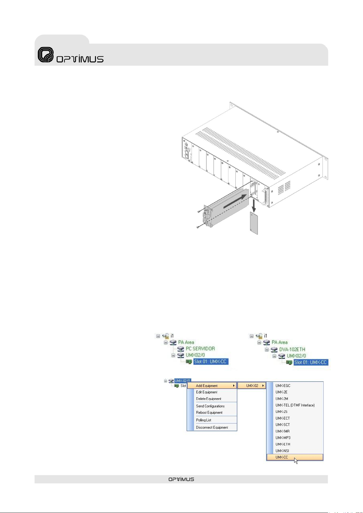
function, which allows a smooth data circulation through the IP network, is carried out by the UMX-CC
card inserted in the UMX-02/0 mainframe.
The data management can be local (between equipments belonging to the same PA Area) or global
(between equipments belonging to different PA Area and/or servers).
The data management at local level uses the so-called LCC process: Local Congestion Controller. Each PA
Area requires, at minimum, one LCC process.
The data management at global level uses the so-called GCC process: Global Congestion Controller. In
case of several PA Areas in one installation with pagings and music programs broadcasting requirements
between the PA Areas, one GCC process at minimum is required.
Principal characteristics:
Double Ethernet connection for installations with redundant
network systems.
Each card occupies a position on the bus of a UMX-02/0.
Stand-alone operation mode or by P.A. Manager control
software.
Surveillance of equipment operation by means of P.A. Manager
software and/or basic TELNET functions.
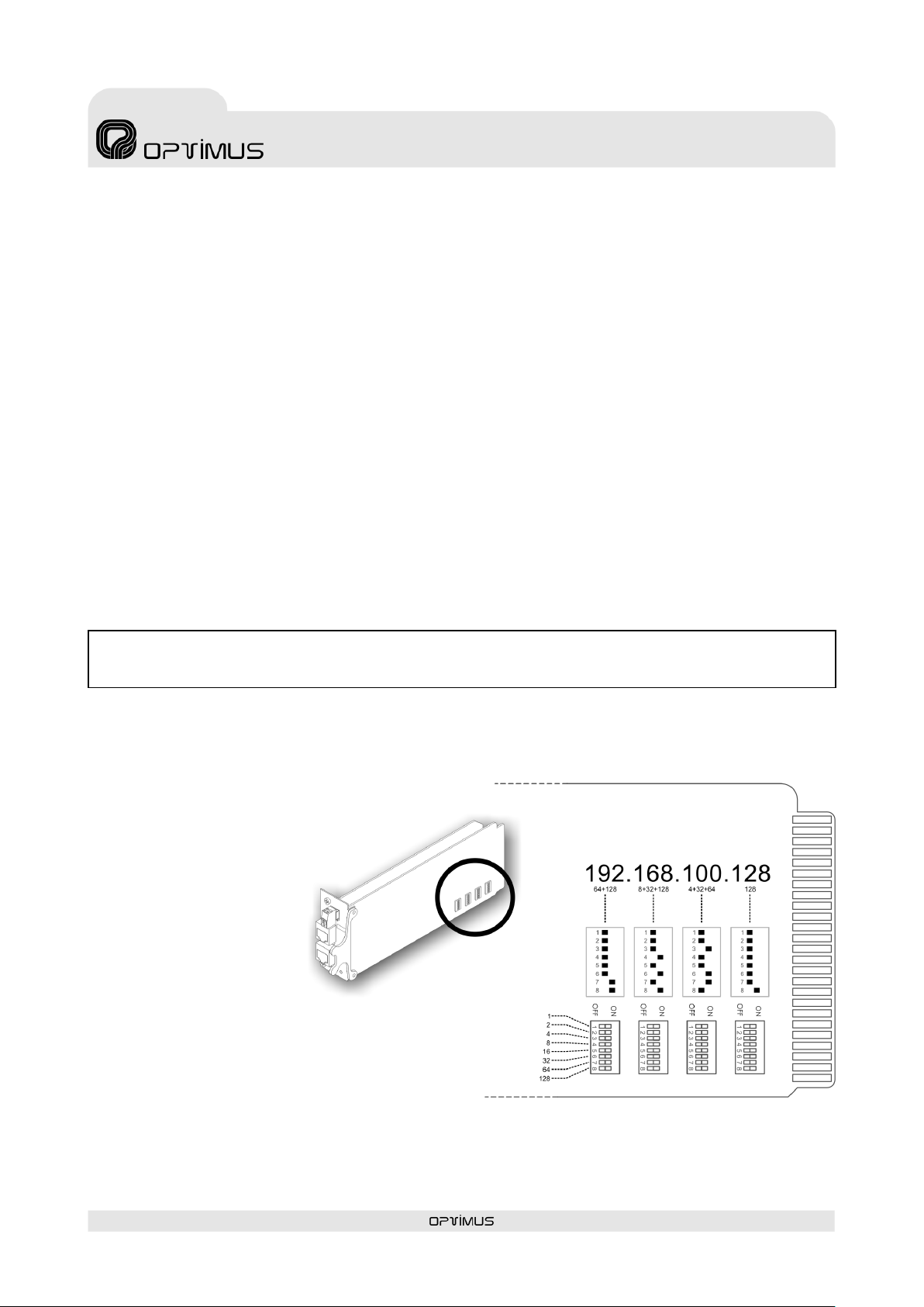
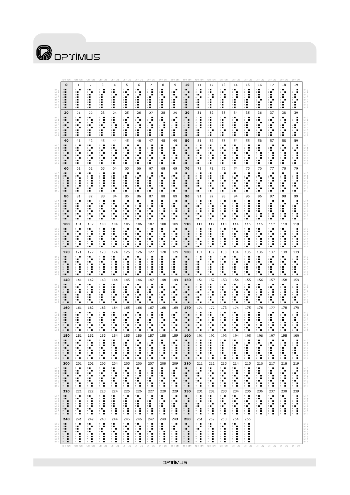
IP address configuration by means of DIP switches, facilitating
the replacement of equipment in an installation, or remotely
through software.
2. ELEMENTS
(1) CTRL OUT strip. Not used.
(2) ETHERNET A connector
RJ45 type connector. Used for connection to the
ETHERNET network. Cat 5 STP cable must be
used for its connection.
(3) ETHERNET B connector
RJ45 type connector. Used, in a redundant
network, as a secondary connection to the
ETHERNET network. Cat 5 STP cable must be
used for its connection.
If the connection to ETH A fails, the card
automatically uses this connection, so that the PA
system continues to operate.
(4) ETHERNET A input 10 Mb LED indicator
Indicates the speed of the IP network connected
to the ETHERNET A input. If the LED is lit, it
indicates a speed of 10 Mb. If unlit, it indicates a
network speed of 100 Mb (use of a transmission
speed of 100 Mbps is highly recommended).
(5) ETHERNET A input ACT LED indicator
ACTIVITY indicator. It lights when data is being
sent or received through the ETHERNET A input.
(6) ETHERNET A input LINK LED indicator
When lit, it indicates connection of the ETHERNET
A input to the IP network.
(7) ETHERNET B input 10 Mb, ACT and LINK
LED indicators
These serve the same purpose as the ETHERNET
A indicators, applied in this case to the
ETHERNET B input.
Figure 1

UMX-CC version 1.0
7
AUDIO IP MANAGEMENT CARD
FOR UMX-02/0 MODULAR MATRIX
UMX-CC
R&D Department
NB: The IP address can also be set by software. To do this, refer to section 4. If this action is taken, the configuration DIP
switches stop to be operative.
3. STARTING UP A UMX-CC CARD
To start a UMX-CC, proceed as follows:
1. Configure the IP address of the card. Refer to section 3.1.
2. Position the card in the UMX-02/0 chassis and make the connections. Refer to section 3.2.
3. Add the card to the installation by means of the P.A. Manager software. Refer to section 3.3.
4. Configure the parameters of the card. Refer to section 3.4.
5. Connect the UMX-02/0 unit to the installation structure. Refer to section 3.5.
6. Send configurations to the unit. Refer to section 3.6.
3.1. Configuration of the IP address
Before positioning the card in a UMX-02/0 chassis, its IP address must be configured. For this purpose, it
has 4 internal DIP switches (see Figure 2).
The IP address of the card is configured by means of these 4 DIP switches. This address identifies the
card in the network, and so each equipment unit must have a unique IP address.
An IP address is represented by means of a 32-bit binary number. The IP addresses are expressed as
decimal notation numbers: the 32 bits of the address are divided into four octets (an octet is a group of 8
bits). On the card each octet is configured through a DIP switch (four octets four DIP switches).
In an octet, each bit can
have the value 0 (DIP switch
OFF) or 1 (DIP switch ON).
In order to obtain the
decimal value of the octet,
the decimal values of each
bit that is in the ON position
must be added up (from the
top down: 1, 2, 4, 8, 16, 32,
64 and 128).
Figure 2 shows an example
in which the IP address
192.168.100.128 is
configured.
Table I on the next page
shows all the DIP switch
combinations from 0 to 255.
Figure 2

UMX-CC version 1.0
8
AUDIO IP MANAGEMENT CARD
FOR UMX-02/0 MODULAR MATRIX
UMX-CC
R&D Department
Table I. Configuration of the IP address.

UMX-CC version 1.0
9
AUDIO IP MANAGEMENT CARD
FOR UMX-02/0 MODULAR MATRIX
UMX-CC
R&D Department
3.2. Positioning the card in the UMX-02/0 chassis and connections
1. Move the front switch on the UMX-02/0 to
the OFF position or disconnect the power
strip.
2. Unscrew the two attachment screws and
remove the blank panel from the position
where the card has to be installed.
3. Insert the card.
4. Fasten the attachment screws.
5. Connect the UMX-CC card to the IP network
of the installation by means of RJ45
connector A or B.
6. Connect the power supply to the UMX-02/0
chassis and move the front switch to ON.
3.3. Adding the card to the installation by means of the P.A. Manager
software
To configure the card, it is necessary to have a PC connected to the network that has the SCF-01 or SCM-
01 (P.A. Manager) software.
1. If the software is the SCM-01, start the application, open the Options menu and select Installations
(administrator user level is required). If the software is the SCF-01, start the application.
NB:
Prior to configuration of the parameters of the UMX-CC card, it is necessary to have configured the Installation and PA Area
parameters.
The UMX-CC card must be added to
a UMX-02/0 chassis, which in turn
can depend on a P.A. Area or a DVA-
102ETH.
2. Select the UMX-02/0 chassis to
which you wish to add the UMX-CC
card.
3. Open the Add Equipment menu, select
UMX-02 and click on UMX-CC.
4. The unit configuration screen appears.
Refer to section 3.4. Configuration of
the parameters of the UMX-CC card.
Figure 3

UMX-CC version 1.0
10
AUDIO IP MANAGEMENT CARD
FOR UMX-02/0 MODULAR MATRIX
UMX-CC
R&D Department
3.4. Configuration of the parameters of the UMX-CC card
(1) Slot
Position occupied by the card in the
UMX-02/0 chassis.
(2) Name
Enter a name to identify the equipment unit. Maximum of
50 characters.
IP DATA
(3) IP address
IP address of the UMX-CC card. This must coincide with
the configuration of the DIP switches of the card or with
the address configured through the Web connection. It
must be a fixed IP address.
(4) Netmask and (5) Gateway
In installations that require this. Consult the network
administrator of the installation
MULTICAST DATA (also see page 10))
(6) IP Multicast
Default setting 239.5.5.5. Do not modify this field unless
the installation topology makes it necessary. All the units
with an IP connection in the installation must have the
same IP multicast address.
(7) Multicast port
Default setting 5000. Do not modify this field unless the
installation topology makes it necessary. All units with an
IP connection in the installation must have the same
multicast port.
(8) Send “Heart Beat” every (n) seconds
Frequency with which the unit sends a heart beat signal to the multicast group. This signal informs the
other equipment units in the installation that the system is operating perfectly.
(9) Local Manager and (12) Global Manager
Defines whether the UMX-CC card is to function as a priority manager of the Optimax system, either
locally at PA Area level or globally for the installation, and establishes the priority of this management
with respect to other equipment units (1 = maximum priority). See Notes on Local and Global Co-
ordinators on page 12.
(2)
(4)
(5)
(6)
(7)
(8)
(9)
(10)
(3)
(1)

UMX-CC version 1.0
11
AUDIO IP MANAGEMENT CARD
FOR UMX-02/0 MODULAR MATRIX
UMX-CC
R&D Department
a. Multicast configuration
It is possible to modify the multicast
configuration of all the equipment
units in the installation
simultaneously. Proceed as follows:
1. From the installation screen,
open the Options menu and
select Multicast Configuration.
2 A window with the configurations
of the multicast group appears.
Double click on the data item
that you wish to change.
3 Modify the value and click on
Accept.
4. Confirm the change by clicking on Yes.
5. Close the Multicast Configuration window by clicking on OK.
ATTENTION: The values that are modified from the Multicast Configuration window affect all the equipment units in the
multicast group in the installation.

UMX-CC version 1.0
12
AUDIO IP MANAGEMENT CARD
FOR UMX-02/0 MODULAR MATRIX
UMX-CC
R&D Department
b. Default base Multicast addresses, ports and configurations
Broadcast address
Broadcast port
Initial configuration download
255.255.255.255
3333
Multicast address
Multicast port
Initial configuration download
239.5.5.5
8001
Multicast address
Multicast port
Others
Control data
239.5.5.5
5000
Heart beat every 10 seconds
Global audio channels
239.1.0.x
6000 + x
8 simultaneous channels
Local audio channels
239.1.PAArea.x
6000 + (PAArea*100) + x
5 simultaneous channels
Valid ranges (according to the IANA Guidelines for IPv4 Multicast Address)
Multicast address
Multicast port
Others
Control data
Between 239.0.0.0 and
239.255.255.255
Between 1025 and 65536
Heart beat between 1 and 65000
seconds.
Global audio channels
Between 239.0.0.0 and
239.255.255.255
Between 1025 and 65536
1-50 simultaneous channels
Local audio channels
Between 239.0.0.0 and
239.255.255.255
Between 1025 and 65536
1-50 simultaneous channels
c. Notes on Local and Global Co-ordinators
The system requires management of the digital audio channels at all times, so that the data may circulate freely across the network.
This function is performed by two applications: one at a local level, known as LCC, which manages the digital channels at PA Area
level, and another, known as GCC, which manages the digital channels at a global level (between different PA areas and/or servers).
Each PA Area needs at least one LCC process on one of its equipment units.
If there is more than one PA Area in an installation, and announcements have to made or music programs have to be sent between
PA Areas, a minimum of one GCC process is required on an equipment unit in the installation.
If the number of equipment units so permits, it is advisable to have each process available on at least two equipment units. In this
way, the applications continue to work even when a fault in one of the equipment units occurs.
There are specific equipment to run these applications: CC-100ETH, UMX-CC and UMX-ETH (Control). It is recommended that they
are the ones who made the role of coordinator. If these equipment are not present in the installation, it is advisable that the COU-
02/0ETH, performs the functions of co-ordinator.
The recommended order of priority depending on the model is as follows:
CC-100ETH
UMX-CC
UMX-ETH
(Control)
COU-02/0ETH
SU-114N
SU-214/0N
UP-xETH
(Back up amplifier)
UP-xETH
UMX-ETH
(program
o priority)
DVA-102ETH
DC-600ETH
FC-600ETH
>
>
>
>
>

UMX-CC version 1.0
13
AUDIO IP MANAGEMENT CARD
FOR UMX-02/0 MODULAR MATRIX
UMX-CC
R&D Department
NOTE: If one UMX-CC card is added or its configuration is modified, it is necessary to send configurations to all
the Optimax equipments in the installation.
3.5. Connecting the equipment in the installation structure
When equipment units are added to the installation, they appear in the structure with their name in red,
preceded by the “disconnection” icon. While their status is shown as disconnected, these equipment units
are not operative.
To connect the equipment, proceed as follows:
1. In the installation structure, right click with the mouse on the
disconnected equipment unit.
2. Click on Connect Equipment. The connection icon appears and the
name of the equipment unit is shown in green.
3.6. Sending configurations to a UMX-CC card
1. Before sending configurations to any equipment unit, it is advisable to save the configuration. To do
this, from the P.A. Manager software installation screen, open the File menu and select Save.
1. On the installation tree, right click with the mouse on the name of the UMX-CC card and select the
option Send configurations.
2. A progress bar appears. Upon completion, click on OK.
4. CONFIGURATION OF THE UNIT IP ADDRESS BY
SOFTWARE
It is possible to change the IP address of the UMX-CC card by
means of the DIP switches situated on the underside of the
unit or remotely through the software.
To make the change by software, from the installation screen
of the P.A. Manager software right click with the mouse on the
name of the unit and select the option Web Connection (1).
If the PC is remote with respect to the installation, open the
Internet browser and enter the IP of the unit in the address
bar (for example: http://10.1.1.2). This IP address is the
address configured through the IP configuration DIP switches
of the UMX-CC card.
(1)
= Equipment disconnected
= Equipment connected

UMX-CC version 1.0
14
AUDIO IP MANAGEMENT CARD
FOR UMX-02/0 MODULAR MATRIX
UMX-CC
R&D Department
ATTENTION
If you activate the IP by software, the
functionality of IP address selection by
DIP switches will be deactivated.
Once the change has been made, it can
be undone by deleting the IP software via
the web, or by selecting the address
0.0.0.0 on the DIP switches and restarting
the unit.
In both cases, a web page belonging to
the unit will load.
Proceed as follows:
1. Enter the password in the Administrator
Login section (2) (contact technical staff
at Optimus and they will provide you
with this) and click on Login (3).
2. Open the Expert menu (4) and click on
the Set IP address option (5).
3. Write the new IP in the IP Address field
(6) (for example: 10.1.1.100) and click
on Save IP Address (7).
ATENCIÓN
Once the IP address of the unit has been
changed, it is necessary to modify this in
the P.A. Manager software as well (see
section 3.4) and to send configurations to
the UMX-CC card (see section 3.6).
NB: To be able to view the page, it is
necessary to deactivate the proxy in the
configuration of the web page browser.
(4)
(5)
(2)
(3)
(6)
(7)

UMX-CC version 1.0
15
AUDIO IP MANAGEMENT CARD
FOR UMX-02/0 MODULAR MATRIX
UMX-CC
R&D Department
5. NETWORK SPECIFICATIONS
The Optimax PA system supports audio and control data communication through Ethernet and IP
networks. Since it works on levels 3 and 4 of the OSI scale, the Optimax protocol supports
communication through routers (IP protocol) by means of the configurations of the gateways and
subnetwork masks. Thanks to these features, Optimax can work on both LANs and WANs.
Most of the communications in the Optimax systems use multicast. Multicast is an effective means of
providing transit services from one sender to many receivers. It is absolutely essential to exhaustively
and rigorously check the network configuration in order to ensure that the system operates correctly.
The multicast networks include a wide range of protocols, from filter protocols (IGMP, MLD) to routing
protocols (MOSPF, DVMRP, PIM-DM and PIM-SM/SSM).
Optimax incorporates an application-level control (ACK) (level 7 of the OSI scale) of the management
data sent.
1. Default multicast base addresses, ports and configurations
Broadcast address
Broadcast port
Initial configuration download
255.255.255.255
3333
Multicast address
Multicast port
Initial configuration download
239.5.5.5
8001
Multicast address
Multicast port
Others
Control data
239.5.5.5
5000
Heart beat every 10 seconds
Global audio channels
239.1.0.x
6000 + x
8 simultaneous channels
Local audio channels
239.1.PAArea.x
6000 + (PAArea*100) + x
5 simultaneous channels
2. Valid ranges (according to the IANA Guidelines for IPv4 Multicast Address)
Multicast address
Multicast port
Others
Control data
Between 239.0.0.0 and
239.255.255.255
Between 1025 and 65536
Heart beat between 1 and 65000
seconds.
Global audio channels
Between 239.0.0.0 and
239.255.255.255
Between 1025 and 65536
1-50 simultaneous channels
Local audio channels
Between 239.0.0.0 and
239.255.255.255
Between 1025 and 65536
1-50 simultaneous channels
3. Local network (LAN) specifications
-Dedicated VLAN
-Bandwidth: 4 Mb for each audio channel
-Number of audio channels:
Up to 50 global channels (from the exchange to the satellites)
Up to 50 local channels (internal to the satellite, they do not consume backbone bandwidth)

UMX-CC version 1.0
16
AUDIO IP MANAGEMENT CARD
FOR UMX-02/0 MODULAR MATRIX
UMX-CC
R&D Department
4. Switch/router specifications for LAN and
WAN networks
-Protocols:
UDP/ IP multicast for Audio
UDP/ IP multicast for Control. Security of
reception by means of ACK management
protocol in Application Layer
-Multicast snooping:
Multicast filtering
IGMP v2
-For large installations:
Multicast routing (Spanning Tree)
Capacity to handle TOS (Type Of Service)
5. Certified hardware
-Large installations:
Nortel: BayStack 470, Ethernet Routing
Switch 3510 and higher
Cisco: 36XX or higher
Alcatel: Level 3 switches
-Medium-sized installations:
NKF: XSNET 1800
Hirschmann: RS30-0802O6O6SDAEHH01.0
-Small installations, with a proprietary
network:
Nortel: BayStack 425
Cisco: 500G and 29600 families
Equitel: N950
6. Network protocol stack
(*) Multicast addresses and reserved ports

UMX-CC version 1.0
17
AUDIO IP MANAGEMENT CARD
FOR UMX-02/0 MODULAR MATRIX
UMX-CC
R&D Department
6. TECHNICAL SPECIFICATIONS
Connections
ETH A and ETH B (Redundant system)
Consumption
100 mA
7. SOFTWARE AND FIRMWARE VERSIONS
The functionalities described in this user’s manual are valid for the following software and firmware
versions (or later versions):
Firmware UMX-CC
Update 2.6.19
P.A. Manager Software
Version 2.6 / Revision 4114.28490
Optimus Flasher Software
Version 2.6.9
8. DOCUMENT VERSION TRACKING
Reference system
Type of Document
Confidentiality
N/A
Optimax
Installation and operation guide
Rev
Date
Modifications Content
Written by:
1.0
04/2011
First version
R&D Department
Approved By
Function
Date
Ferran Gironès i Puig
R&D Director
04/2011

UMX-CC version 1.0
18
AUDIO IP MANAGEMENT CARD
FOR UMX-02/0 MODULAR MATRIX
UMX-CC
R&D Department
9. GUARANTEE
1. GUARANTEE CERTIFICATE
1. OPTIMUS S.A. guarantees that its products are free from material and
manufacturing defects when they are first delivered to the purchaser.
2. In accordance with the conditions outlined here, OPTIMUS S.A.
guarantees its products for two (2) years from the date on which the
purchaser acquires the product. If, within this guarantee period, defects
appear which are not due to factors outlined in section 2, OPTIMUS S.A.
shall replace or repair the unit using equivalent, new or reconstructed
replacement parts, as it deems fit. If replacement parts are applied which
improve the unit, OPTIMUS S.A. reserves the right to charge the client for
the additional cost of these components.
3. No guarantee benefits shall be provided other than those cited here.
4. In order to claim the guarantee rights, it shall be an essential
requirement to present the original purchase invoice or the guarantee
certificate.
2. GUARANTEE PROVISIONS
1. In the event that the product had to be modified or adapted to comply
with local requirements concerning technical specifications or safety, and if
the country in question is not the country for which the product was
originally designed and manufactured, defects are not considered to be
material or manufacturing defects. Furthermore, the guarantee does not
cover the execution of these modifications or adaptations, regardless of
whether or not they have been carried out correctly.
Nor shall OPTIMUS S.A. be responsible for any costs under this guarantee
for these types of modifications.
2. The guarantee shall not entitle the purchaser to inspection or free
maintenance or repair of the unit, particularly if the defects are due to
inappropriate use. Nor do the guarantee rights cover defects in wearing
parts that become worn as a result of normal wear and tear. Wearing parts
are, in particular, potentiometers, switches/keys, and similar parts.
3. The guarantee does not cover defects in the equipment unit caused by:
Abuse or incorrect use of the unit for purposes other than those for
which it is intended, in non-compliance with the service and
maintenance instructions specified in the Manual and/or Technical
Instructions for the unit.
Connection or use of the product in a manner that does not correspond
to the technical or safety requirements of the country in which the unit
is used.
Installation in conditions other than those indicated in the Manual
and/or Technical Instructions.
Deficiency or interruptions in the electricity supply or installation
defects which imply use in abnormal conditions.
Damage caused by other equipment units that are connected to the
product.
The use or installation of Software (programmes), interfaces, parts or
supplies not provided and/or not authorised by OPTIMUS S.A.
Failure to use the original packaging for transportation.
Damage caused by force majeure or other causes not attributable to
OPTIMUS S.A.
4. The following elements are not covered by this guarantee:
All plastic surfaces and all parts exposed to outdoor conditions which
have been scratched or damaged as a result of normal or abnormal
use.
Breakages, knocks, damage due to a fall or scratches caused by
moving the unit in any way.
Damage caused by tests, use, maintenance, installation or
inappropriate adjustments, or as a result of any alteration or
modification of any kind not carried out by a Service Authorised by
OPTIMUS S.A. in compliance with this guarantee.
Damage to persons or property that might be caused by the improper
use of the equipment, including lack of maintenance.
5. The guarantee shall not be valid whenever the following is observed:
Amendments or corrections made to the details of the guarantee
certificate or purchase invoice.
Failure to produce the original invoice or the absence of a date on this.
Absence of the serial or batch number on the equipment.
6. In the case of personal computers, the guarantee will not cover the
elimination of computer viruses, the restoration of programmes damaged
by these or the reinstallation of the disk following its deletion.
7. The rights of this guarantee are invalidated if the product has been
repaired or opened by staff unauthorised by OPTIMUS S.A. or by the client
himself.
8. If OPTIMUS S.A. were to establish before the client that the damage
affecting the unit does not entitle a claim to be made under the guarantee,
the costs of checking the equipment incurred by OPTIMUS S.A. shall be
borne by the client.
9. Products not covered by the guarantee shall only be repaired once
payment has been effected by the client. In the event that the guarantee
rights do not apply, OPTIMUS S.A. shall duly inform the client. If, within a
period of 6 weeks from this communication, no written repair order is
received from the client confirming acceptance of the costs, OPTIMUS S.A.
shall return the unit in question to the client. In this case, the transport and
packaging costs shall be invoiced separately and payment shall be made on
delivery. In the event that a repair order is sent by the client, confirming
that he assumes the costs of repair, the transport and packaging costs shall
be invoiced additionally, and also separately.
10. If the equipment needs to be transferred to the Authorised Service
Centre, transportation shall be effected by the responsible party according
to the guarantee, who will also bear the freight and insurance costs.
11. In the event of a defect, OPTIMUS S.A. guarantees that the repair
and/or replacement of parts so that the unit operates correctly will be made
within a period of no more than 30 days. Nevertheless, OPTIMUS S.A.
would like to clarify that the normal period does not exceed 30 days.
12. All parts or products replaced as part of the guarantee services shall
become the property of OPTIMUS S.A.
3. TRANSFER OF GUARANTEE
The guarantee is solely awarded to the original purchaser (principal client)
and is not transferable. With the exception of OPTIMUS S.A., no third party
(dealers, etc.) is authorised to award additional guarantees on behalf of
OPTIMUS S.A.
4. CLAIMS FOR DAMAGE
In the event that OPTIMUS S.A. cannot provide a suitable guarantee
service, the purchaser shall not be entitled to claim any indemnity for
damages arising. The responsibility held by OPTIMUS S.A. is limited in all
cases to the invoicing price of the product.
5. RELATION WITH OTHER GUARANTEE RIGHTS AND NATIONAL
LAW
1. This guarantee does not affect the rights of the purchaser with respect to
the vendor arising from the contract of sale accomplished.
2. These conditions of the guarantee provided by OPTIMUS S.A. are valid as
long as they do not contradict the corresponding national law on guarantee
provisions.
3. OPTIMUS S.A. guarantees that this product complies with the safety
regulations in force in the country.
THIS LIMITED GUARANTEE DECLARATION IS THE EXCLUSIVE GUARANTEE
OFFERED BY OPTIMUS S.A. ALL OTHER EXPLICIT OR IMPLICIT
GUARANTEES ARE EXCLUDED, AND THIS ALSO APPLIES TO GUARANTEES
OF MARKETABILITY AND SUITABILITY FOR A PARTICULAR PURPOSE.
(EXCEPT WHEN THESE GUARANTEES ARE REQUIRED BY AN APPLICABLE
LAW). NO GUARANTEE, EITHER EXPLICIT OR IMPLICIT, SHALL BE APPLIED
ONCE THE GUARANTEE PERIOD HAS EXPIRED
OPTIMUS S.A.
After-Sales Service
C/ Barcelona 101
17003 - GIRONA
Tel. 902 151 96 / 972 203 300
Fax. 972 21 84 13
Table of contents
Other Optimus Control Unit manuals
Popular Control Unit manuals by other brands

Philips
Philips Dynalite DDTC001 installation instructions

Danfoss
Danfoss EH Series Service manual

Zeta Alarm Limited
Zeta Alarm Limited SmartConnect Multiloop instruction manual

Turbo
Turbo EIT Series user manual

Dormakaba
Dormakaba ED connection board CAN Assembly instruction

TEGO
TEGO Roundline Master quick start guide