Optimus 31-3040 User manual

STAND BY
SFC
MODE
DOLBY
PRO LOGIC 5-D
THEATER LOUDNESS
VCR
TAPE 1
TAPE 2
MONITOR
DVD/TV LD/SAT CD TUNER PHONO
VOLUME
MAXMIN
MULTI
JOG
PHONES
POWER
DOLBY SURROUND
PRO•LOGIC
STAV-3690 AUDIO/VIDEO RECEIVER
OSR
INTELLIGENT SYSTEM REMOTE
DIGITAL
SIGNAL
PROCESSOR
DSP
VIDEO L AUDIO R
VIDEO INPUT SELECTCLASSFM MONORETURN
BALANCE
TREBLE
BASS
SPEAKERS MEMORY FM/AM ENTER
RL
BA
Cat. No. 31-3040
Owner’s Manual
Please read before using this equipment.
STAV-3690
Audio/Video
Receiver

2
Introducing the Optimus STAV-3690
Your Optimus STAV-3690 Audio/Video Receiver is the perfect control center for
your audio/video system. It combines 500 watts total Pro Logic‘ Surround
Sound power with five equal-power discrete amplifiers, and provides connec-
tions for one tape deck, one VCR, two more tape decks or audio/video playback
sources, a turntable, a CD player, and a video monitor, plus front panel audio/
video input jacks for connecting one more audio/video device such as a cam-
corder.
Your receiver also has special sound options.
Dolby Pro Logic Surround Sound
delivers movie theater sound for audio/video programs (especially those en-
coded with Dolby Surround Sound signals).
Dolby 3CH Logic
provides a wider
sound field than ordinary playback.
SFC Effects
creates a listening environment
that simulates a concert hall, jazz club, recording studio, or a live performance.
5D Theater
provides clear dynamic sound effects by sending audio signals
through the rear channel to simulate stereo sounds.
Additional features include:
Digital-Synthesized Tuner Precisely tunes to AM and FM stations.
30 Memory Locations Let you store and recall the frequencies for up to 30 AM/FM stations.
Multi-Jog Tuning Offers you a simple tuning method for either stored stations or the entire fre-
quency range.
Subwoofer Output Lets you easily connect an amplified subwoofer that delivers the very low fre-
quency bass sounds, to bring out the richness and depth of music plus the full
impact of motion-picture special effects, for sound you can actually feel.
Tape Monitoring Lets you listen to the actual recording as you record, if your tape deck has a
tape-monitoring feature.
Built-In Protection Circuits Automatically turn off the receiver to help avoid power surges or short circuit
damage.
Trainable Remote Control Lets you use a single remote control for the receiver and other compatible com-
ponents connected to the receiver.
Note: The remote control requires two AAA batteries (not supplied).
We recommend you record the receiver’s serial number here. The number is on the
receiver’s back panel.
Serial Number:_____________________________________________
Note to the Cable TV System Installer:
This reminder is provided to call the CATV system installer’s attention to Article 820-40 of the National Electrical Code that
provides guidelines for proper grounding and, in particular, specifies that the cable ground shall be connected to the ground-
ing system of the building as close to the point of cable entry as practical.
Manufactured under license from Dolby Laboratories Licensing Corporation.
Dolby, Pro Logic, and the double-D symbol ( ) are trademarks of Dolby Laboratories Licensing Corporation.
1997 Tandy Corporation.
All Rights Reserved.
Optimus and RadioShack are registered trademarks used by Tandy Corporation.

3
This receiver is made and tested to meet exacting
safety standards. It meets both UL and FCC require-
ments.
WARNING: TO REDUCE THE RISK OF
FIRE OR ELECTRIC SHOCK, DO NOT
EXPOSE THIS APPLIAANCE TO RAIN OR
MOISTURE.
This symbol is intended to alert you to the
presence of uninsulated dangerous voltage
within the system’s enclosure that might be of
sufficient magnitude to constitute a risk of
electric shock. Do not open the system’s
case.
This symbolis intendedto inform you that im-
portant operating and maintenance instruc-
tions are included in the literature acc-
ompanying this system.
CAUTION
Power Lines—Locate an outdoor antenna away from
power lines.
Nonuse Periods—Unplug the receiver’s power cord
when you will not use it for extended periods.
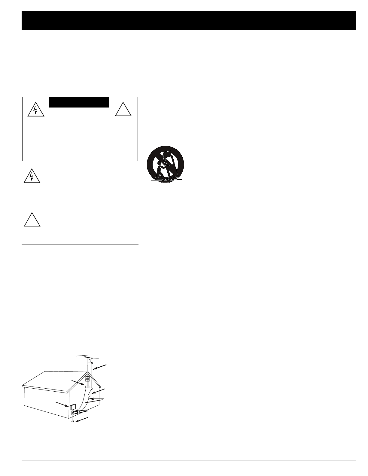
Outdoor Antenna Grounding—If an outside antenna
or cable system is connected to the receiver, ground
the antenna or cable system so as to provide some
protection against voltage surges and built-up static
charges. Article 810 of the National Electrical Code,
ANSI/NFPA 80, provides information about proper
grounding of the mast and supporting structure,
grounding of the lead-in wire to an antenna discharge
unit, size of grounding conductors, location of antenna-
discharge unit, connection to grounding electrodes,
and requirements for the grounding electrode. See the
example below.
RISK OF ELECTRIC SHOCK.
DO NOT OPEN.
CAUTION: TO REDUCE THE RISK OF
ELECTRIC SHOCK, DO NOT REMOVE
COVER OR BACK. NO USER-SERVICE-
ABLE PARTS INSIDE. REFER SERVICING
TO QUALIFIED PERSONNEL.
CAUTION !
!
Antenna
Lead-In
Wire
Antenna
Discharge Unit
(NEC Section 810-20)
Grounding Conductor
s
(NEC Section 810-21)
Grounding Clamps
Power Service Grounding
Electrode System
(
NEC Article 250
,
Part H
)
Ground Clamp
Electric
Service
Equipment
NEC -- National Electrical Code
IMPORTANT SAFETY INSTRUCTIONS
Careful attention is devoted to quality standards in the manufacture of your receiver, and safety i
s
a major factor in its design. However, safety is also your responsibility.
This section lists important information that will help you properly use and enjoy your receiver an
d
accessories. Read all the included safety and operating instructions before using your receiver.Fol
-
low them closely, and retain them for future reference.
Heed Warnings — Follow all warnings on the product and in the operating instructions.
Cleaning — Unplug this product from the wall outlet before cleaning. Use only a damp cloth fo
r
cleaning. Do not use liquid or aerosol cleaners.
Attachments — Do not use attachments/accessories not recommended by the product manufac
-
turer, as they might create a hazard.
Water and Moisture — Do not use thisproduct near water (for example,near a bathtub,washbowl
,
kitchen sink, or laundry tub; in a wet basement; or near a swimming pool).
Accessories — Do not place this product on an unstable cart, stand, tripod, bracket, or table. Th
e
product may fall, causing serious injury to a child or adult, and serious damage to the product. Us
e
only with a cart, stand, tripod, bracket, or table recommended by the manufacturer or sold with th
e
product. Follow the manufacturer's instructions for mounting, and use a recommended mountin
g
accessory. Carts — Move the product on a cart carefully. Quick stops, excessive force, an
d
uneven surfaces may cause the product/cart to overturn.
Ventilation — Slots and openings in the cabinet provide ventilation, ensure reli
-
able operation, and protect from overheating. Do not block or cover these open
-
ings, and do not place the product on a bed, sofa, rug, or other similar surface. D
o
not place the product in a built-in bookcase or rack unless it provides proper ven
-
tilation as specified by the manufacturer.
Power Sources — Operate this product using only the power sourceindicated on itsmarking label
.
If you are not sure of your home's power type, consult your product dealer or local power company
.
Polarization — This product is equipped with a polarized AC line plug (a plug having one blad
e
wider than the other). This plug will fit in the power outlet only one way. This is a safety feature. I
f
you cannot insert the plug fully into the outlet, try reversing the plug. If the plug still doesn't fit, con
-
tact your electrician to replace your obsolete outlet. Do not defeat the safety purpose of the polar
-
ized plug. If you need an extension, use a polarized cord.
Power-Cord Protection — Route power-supply cords so they are not likely to be walked on o
r
pinched by items placed on or against them, paying particular attention to cords at plugs, conve
-
nience receptacles, and the point where they exit from the product.
Lightning — For added protection for this product during a lightning storm, or when it is left unat
-
tended and unused for long periods of time,unplug itfrom the walloutlet and disconnecttheanten
-
na orcable system.Thiswill prevent damage to the product due tolightning and power-line surges
.
Overloading — Do notoverload wall outlets, extension cords, or integral convenience receptacles
,
as this can result in a risk of fire or electric shock.
Objects and Liquids — Never push objects of any kind into this product through openings, as the
y
may touch dangerous voltage points or short out parts that could result in a fire or electric shock
.
Never spill liquid of any kind on the product.
Servicing — Do not attempt to service this product yourself, as opening or removing covers ma
y
expose you to dangerous voltage or other hazards. Refer all servicing to qualified service person
-
nel.
Damage Requiring Service — Unplug this product from the wall outletand refer servicing to qual
-
ified service personnel under the following conditions:
• When the power-supply cord or plug is damaged.
• If liquid has been spilled or objects have fallen into the product.
• If the product has been exposed to rain or water.
• If the product does not operate normally by following the operating instructions. Adjust onl
y
those controls that are covered by the operating instructions, as an improper adjustment o
f
other controls may result in damage and will often require extensive work by a qualified techni
-
cian to restore the product to normal operation.
• If the product has been dropped or damaged in any way.
• When the product exhibits a distinct change in performance.
Replacement Parts — When replacement parts are required, be sure the service technician use
s
replacement parts specified by the manufacturer or having the same characteristics as the origina
l
part. Unauthorized substitutions may result in fire, electric shock, or other hazards.
Safety Check — Upon completion of service or repairs to this product, ask the service technicia
n
to perform safety checks to determine that the product is in proper operating condition.
Wall or Ceiling Mount — The product should bemounted to a wall orceiling only as recommende
d
by the manufacturer.
Heat — The product should be situated away from heat sources such as radiators, heat registers
,
stoves, or other products (including amplifiers) that produce heat.

4
Contents
P
reparing Your Receiver . . . . . . . . . . . . . . . . . . . . . . . . . . . . . . . . . . . . . . . . . . . . . . . . . . . . . . . . . . . . . . . . . . . . . . . . . . . . . 5
Positioning Speakers . . . . . . . . . . . . . . . . . . . . . . . . . . . . . . . . . . . . . . . . . . . . . . . . . . . . . . . . . . . . . . . . . . . . . . . . . . .5
Connecting Speakers . . . . . . . . . . . . . . . . . . . . . . . . . . . . . . . . . . . . . . . . . . . . . . . . . . . . . . . . . . . . . . . . . . . . . . . . . . 6
Connecting Program Sources . . . . . . . . . . . . . . . . . . . . . . . . . . . . . . . . . . . . . . . . . . . . . . . . . . . . . . . . . . . . . . . . . . . . 9
Connecting the Antennas . . . . . . . . . . . . . . . . . . . . . . . . . . . . . . . . . . . . . . . . . . . . . . . . . . . . . . . . . . . . . . . . . . . . . . 11
Using One Remote Control for More than One Unit . . . . . . . . . . . . . . . . . . . . . . . . . . . . . . . . . . . . . . . . . . . . . . . . . . 13
Installing the Remote Control’s Batteries . . . . . . . . . . . . . . . . . . . . . . . . . . . . . . . . . . . . . . . . . . . . . . . . . . . . . . . . . . 13
Using the AC Power Outlet . . . . . . . . . . . . . . . . . . . . . . . . . . . . . . . . . . . . . . . . . . . . . . . . . . . . . . . . . . . . . . . . . . . . . 14
Connecting to AC Power . . . . . . . . . . . . . . . . . . . . . . . . . . . . . . . . . . . . . . . . . . . . . . . . . . . . . . . . . . . . . . . . . . . . . . . 14
B
asic Operation . . . . . . . . . . . . . . . . . . . . . . . . . . . . . . . . . . . . . . . . . . . . . . . . . . . . . . . . . . . . . . . . . . . . . . . . . . . . . . . . . . . 15
Balance Control . . . . . . . . . . . . . . . . . . . . . . . . . . . . . . . . . . . . . . . . . . . . . . . . . . . . . . . . . . . . . . . . . . . . . . . . . . . . . 16
Loudness Control . . . . . . . . . . . . . . . . . . . . . . . . . . . . . . . . . . . . . . . . . . . . . . . . . . . . . . . . . . . . . . . . . . . . . . . . . . . . 16
Muting the Receiver . . . . . . . . . . . . . . . . . . . . . . . . . . . . . . . . . . . . . . . . . . . . . . . . . . . . . . . . . . . . . . . . . . . . . . . . . . 16
Using Headphones . . . . . . . . . . . . . . . . . . . . . . . . . . . . . . . . . . . . . . . . . . . . . . . . . . . . . . . . . . . . . . . . . . . . . . . . . . . 16
Tuning the Radio . . . . . . . . . . . . . . . . . . . . . . . . . . . . . . . . . . . . . . . . . . . . . . . . . . . . . . . . . . . . . . . . . . . . . . . . . . . . . 17
Using FM MONO . . . . . . . . . . . . . . . . . . . . . . . . . . . . . . . . . . . . . . . . . . . . . . . . . . . . . . . . . . . . . . . . . . . . . . . . . . . . 18
C
assette Deck/VCR Features . . . . . . . . . . . . . . . . . . . . . . . . . . . . . . . . . . . . . . . . . . . . . . . . . . . . . . . . . . . . . . . . . . . . . . . . 19
Using the VCR/TAPE 1 and TAPE 2 Monitor Buttons . . . . . . . . . . . . . . . . . . . . . . . . . . . . . . . . . . . . . . . . . . . . . . . . . 19
Recording an Audio Source . . . . . . . . . . . . . . . . . . . . . . . . . . . . . . . . . . . . . . . . . . . . . . . . . . . . . . . . . . . . . . . . . . . . 19
Dubbing a Cassette Tape . . . . . . . . . . . . . . . . . . . . . . . . . . . . . . . . . . . . . . . . . . . . . . . . . . . . . . . . . . . . . . . . . . . . . . 19
Playing and Recording Video Tapes . . . . . . . . . . . . . . . . . . . . . . . . . . . . . . . . . . . . . . . . . . . . . . . . . . . . . . . . . . . . . . .20
U
sing Advanced Sound Options . . . . . . . . . . . . . . . . . . . . . . . . . . . . . . . . . . . . . . . . . . . . . . . . . . . . . . . . . . . . . . . . . . . . . .21
Sound Mode Adjustments (Remote Control Only). . . . . . . . . . . . . . . . . . . . . . . . . . . . . . . . . . . . . . . . . . . . . . . . . . . . .22
U
sing the Remote Control . . . . . . . . . . . . . . . . . . . . . . . . . . . . . . . . . . . . . . . . . . . . . . . . . . . . . . . . . . . . . . . . . . . . . . . . . . . 23
Resetting the Remote Control . . . . . . . . . . . . . . . . . . . . . . . . . . . . . . . . . . . . . . . . . . . . . . . . . . . . . . . . . . . . . . . . . . . 25
Training the Remote Control . . . . . . . . . . . . . . . . . . . . . . . . . . . . . . . . . . . . . . . . . . . . . . . . . . . . . . . . . . . . . . . . . . . . 25
T
roubleshooting . . . . . . . . . . . . . . . . . . . . . . . . . . . . . . . . . . . . . . . . . . . . . . . . . . . . . . . . . . . . . . . . . . . . . . . . . . . . . . . . . . . 27
Returning Controls to Factory Defaults . . . . . . . . . . . . . . . . . . . . . . . . . . . . . . . . . . . . . . . . . . . . . . . . . . . . . . . . . . . . 27
C
are and Maintenance . . . . . . . . . . . . . . . . . . . . . . . . . . . . . . . . . . . . . . . . . . . . . . . . . . . . . . . . . . . . . . . . . . . . . . . . . . . . . . 28
T
he FCC Wants You to Know . . . . . . . . . . . . . . . . . . . . . . . . . . . . . . . . . . . . . . . . . . . . . . . . . . . . . . . . . . . . . . . . . . . . . . . . 29
S
pecifications . . . . . . . . . . . . . . . . . . . . . . . . . . . . . . . . . . . . . . . . . . . . . . . . . . . . . . . . . . . . . . . . . . . . . . . . . . . . . . . . . . . . . 30
I
ndex to Features by Control Name . . . . . . . . . . . . . . . . . . . . . . . . . . . . . . . . . . . . . . . . . . . . . . . . . . . . . . . . . . . . . . . . . . . 32

5
Preparing Your Receiver
Positioning Speakers Where you place your speakers (not supplied) can make a noticeable difference
in your system’s sound. The guidelines in this section will help you choose the
best locations. After you use your receiver for a while, you might want to try dif-
ferent locations for your speakers.
Bass response depends largely on speaker location. For strong bass, place the
speakers in the corners of the room. If you want even stronger bass, place the
speakers directly on the floor. If the bass is too strong, move the speakers
slightly away from the corners of the room, or raise them 6 to 18 inches off the
floor. You can buy speaker stands at your local RadioShack store.
The distance between the speakers should be about the same as the distance
between the normal listening point and the point halfway between the speakers.
If you place the speakers too close together, you reduce the stereo separation.
If you place them too far apart, you reduce the bass effect and create a “hole” in
the middle of the sound.
Most speakers have a tweeter dispersion angle of about 60 degrees. Ideally,
your listening position should be just inside the overlap area of tweeter disper-
sion. You can angle the speakers toward you for better stereo effect.
To position your speakers for surround sound, place the A or B (front) speakers
at the front of your listening area, and place the surround (rear) speakers behind
or to the sides of the listening point (see “Using Advanced Sound Options” on
Page 21). Also, place the center speaker above, below, or behind the TV.
Sound might not appear to coincide with the picture if you place it beside the TV
.
Caution: Make all the necessary connections before you plug in or turn on the receiver.
• Surround speakers generally sound
best if you position them above ear
level.
• To avoid interference with the picture
on a nearby TV, use magnetically
shielded speaker systems. This is par-
ticularly important for the center
speaker since it is usually located
closest to the TV.
Center Speaker
Listening
Area
Rear Right
Speaker
Front Right
Speaker
Front Left
Speaker
Rear Left
Speaker
Rear
Front
TV
LR
a
b
a=b
Halfway Point
Between Speak
e
Person in Listenin
g
Area
Normal Listening Point
Halfway Point
Between Speakers
a = b
b
a

6
Preparing Your Receiver
C
onnecting Speakers Preparing the Speaker Wires
Speaker wire consists of two conductors (individual wires) encased in insulation
and is usually color-coded or marked with a ridge along one side so you can
identify each conductor. Use these markings as a guide to help you properly
connect the speakers to your receiver.
Follow these steps to prepare the speaker wires.
1. Cut the speaker wires to the necessary length.
2. Separate the wires about 4 inches on each end.
3. Using a wire stripper, carefully strip about 3/4inch of insulation from the
end of each conductor.
4. Twist the end of each exposed wire to secure any loose strands.
Setting the Impedance Selector Switch
Before connecting speakers, check your speaker system’s impedance (see
your speaker system’s specifications). Normally it is 8W. If it is, leave the IMPED-
ANCE SELECTOR switch set to 8W~16W/ SPEAKER. If your speaker system has 6W
impedance, set the switch to 6Ω~16Ω/SPEAKER.
Follow these guidelines when you select
and connect speakers.
• Be sure you properly connect all
speakers.
• Do not connect two pairs of speakers
to a single set of terminals (A or B) at
the same time. When you use two
pairs of speakers, connect one set to
Speakers A and one set to Speakers
B.
• Realistic, Optimus, and other high-
quality speakers have color-coded
speaker terminals (red for positive po-
larity and black for negative polarity).
Use these color-coded terminals as a
guide to help you properly connect the
speakers to the receiver.
• Use 16-gauge (or larger) speaker wire
for all speaker connections, and con-
sider possible speaker locations be-
fore you decide how much speaker
wire you need.
Wire Strands
Wire Strands
Conductor
Conductor
A
B
A
B
RL
R L
FRONT SPEAKERS
CAUTION: SEE INSTRUCT MANUAL
6 16
8 16 /SPEAKER
/SPEAKER
CAUTION:
SPEAKER IMPEADANCE
816
/SPEAKER
IMPEDANCE
SELECTOR

7
Preparing Your Receiver
Connecting the A and B Speakers
Follow these steps to connect the right speaker to the receiver’s right FRONT
SPEAKERS A terminals.
1. Lift the receiver’s FRONT SPEAKERS A R (+) red lever and insert the ridged
or color-coded conductor’s end into the small hole. Pull down the lever to
secure the conductor.
2. Lift the receiver’s FRONT SPEAKERS A R (–) black lever and insert the other
conductor’s end into the small hole. Pull down the lever to secure the con
-
ductor.
3. Connect the ridged or color-coded conductor’s loose end to the right
speaker’s positive (+) terminal.
4. Connect the remaining loose conductor to the right speaker’s negative (–)
terminal.
Repeat Steps 1–4 to connect the left speaker to the receiver’s left FRONT SPEAK
-
ERS A terminals.
Repeat this entire process to connect a second pair of speakers to the FRONT
SPEAKERS B terminals.
A
B
A
B
RL
R L
FRONT SPEAKERS
L
R
PRE OUT
SUB
WOOFER CENTER
SPEAKER REAR
SPEAKERS
L
R
AUDIO
IN PRE OUT
CENTER
AUDIO
IN
Right Front Speakers A Left
Right Front Speakers B Left
Subwoofer
Amplified
LeftRight Surround
Speakers
Center Speaker
Center Channel
Power Amplifier
Note: Be sure you connect the
receiver’s right and left positive (+) and
negative (–) terminals to the speaker’s
corresponding right and left positive (+)
and negative (–) terminals.

8
Preparing Your Receiver
Connecting Surround-Sound Speakers
You can connect a pair of speakers to the receiver for surround-sound pro-
grams. Follow the steps in “Connecting the A and B Speakers” to connect the
speakers to the REAR SPEAKERS terminals.
Connecting the Center Speaker
The center speaker gives additional ambience to surround sound. Connect the
center speaker to the CENTER SPEAKER terminals. Follow the steps in “Connect-
ing the A and B Speakers.”
Connecting Center Channel and Subwoofer Amplifiers
To increase the center channel’s output power, you can connect an amplifier to
the CENTER PRE OUT jack. Then connect the center channel speaker to the am-
plifier.
Your receiver includes a line-level subwoofer output. Connecting a subwoofer to
your system dramatically extends bass response for incredible richness and
depth. When you listen to surround-sound programs, a subwoofer enhances
your home theater experience by realistically recreating the rumble of an earth-
quake, the bone-jarring percussion of a cannon, and more. To use the subwoof-
er output, simply connect SUBWOOFER PRE OUT to an amplified subwoofer’s line-
level input or to an amplifier to which you have connected a subwoofer.
RadioShack stores sell a variety of suitable subwoofers and amplifiers.

9
Preparing Your Receiver
Connecting Program Sources You can connect up to six external program sources to your receiver.
Connecting a Turntable
Connect a turntable with a magnetic cartridge only. Some older turntables use a
ceramic-type cartridge that does not work with this system.
Connect the turntable’s left and right cables to the receiver’s left and right
PHONO jacks. Then connect the turntable’s ground wire to the receiver’s SIG-
NAL GND terminal.
Connecting a CD Player
To connect a CD player to the receiver, connect the CD player’s left and right
output jacks to the receiver’s CD jacks.
Connecting Cassette Decks
You can connect cassette decks to the VCR/TAPE 1 and the TAPE 2 MONITOR jacks.
Connect the cassette deck’s output jacks to the VCR/TAPE 1 IN (audio) or TAPE 2 IN
PLAY jacks, and connect the cassette deck’s input jacks to VCR/TAPE 1 OUT (au-
dio) or TAPE 2 OUT REC jacks.
You can connect a third cassette deck (for playback only) to the LD/SAT IN (au-
dio) jacks.
Turntable CD Player Cassette Deck Cassette Deck
R
L
R
L
R
L
R
L
L
R
RECPLAYLINE
REC
PLAY INPUTOUTPUT
R
L
OUT PUT
L
R
CD
R
L
R
L
L
R
RECPLAYLINE
REC
PLAY INPUTOUTPUT
L
R
R
L
L
R
L
R
PHONO TAPE2
MONITOR
CD VCR/
TAPE 1
VIDEO
OUT
SIGNAL GND
REC
PLAY
L
R
L
R
IN OUTIN IN
CONTROL
OUT IN
DVD/
TV
IN
TO MONITOR TV
VIDE
O
IN
IN INOUT
LD/
SAT
IN
OUT
IN
Use shielded audio cables with phono
connectors for all audio connections.
Note: If you place the cassette deck
directly above, below, or to the left of the
receiver, the receiver could interfere with
the cassette deck’s operation. If possi-
ble, position the cassette deck to the
right of the receiver or locate it away
from the receiver.

10
Preparing Your Receiver
Connecting Video Sources
If you connect two or more video sources, such as VCRs or laser disc players,
to your receiver, you can use the receiver to select each video source. You can
also use the receiver to easily record from the video sources to the source con-
nected to VCR/TAPE 1.
Connect phono cables from each video source’s audio outputs to the receiver’s
VCR/TAPE 1 or LD/SAT IN (audio) jacks. Then connect phono cables from the re-
ceiver’s VCR/TAPE 1 OUT (audio) jacks to the source’s audio input jacks.
Connect video cables from each video source’s video outputs to the receiver’s
VCR/TAPE 1 VIDEO IN or LD/SAT VIDEO IN jacks. Then connect video cables from the
receiver’s VCR/TAPE 1 VIDEO OUT jack to the VCR’s video input.
You can connect a third video source to the DVD/TV IN jacks. Connect the
source’s video output to the receiver’s DVD/TV VIDEO IN jack, and the source’s au-
dio outputs to the receiver’s DVD/TV IN (audio) jacks.
The front panel VIDEO L AUDIO R jacks accept another audio/video device. These
jacks are convenient for temporarily connecting another video source to the re-
ceiver, such as a camcorder.
Connecting a Video Monitor
The monitor (or TV with baseband video input) you connect to the VIDEO OUT ter-
minal can monitor any program you connect to the receiver’s VCR/TAPE 1, LD/SAT,
or DVD/TV input jacks. Connect a video cable from the receiver’s VIDEO OUT TO
MONITOR TV jack to the monitor’s video input.
TV Monitor LD Player LD PlayerVCR
L
R
RECPLAY
AUDIO
REC
PLAY INPUTOUTPUT
VCR
VIDEO
IN
OUT
VIDEO
IN
V
L
R
AUDIO
OUT
VIDEO
OUT
R
L
V
L
R
AUDIO
OUT VIDEO
OUT
R
L
V
L
R
R
L
R
L
L
R
V
V
V
V
v
L
R
v
L
R
v
PHONO TAPE2
MONITOR
CD VCR/
TAPE 1
VIDEO
OUT
SIGNAL GND
REC
PLAY
L
R
L
R
IN OUTIN IN
CONTROL
OUT IN
DVD/
TV
IN
TO MONITOR TV
VIDEO
IN
IN INOUT
LD/
SAT
IN
OUT
IN
Note: If your VCR is monaural, use a Y-
adapter (available at your local Ra-
dioShack store) to connect the VCR’s
audio output to both the
L
and
R
audio in-
puts on the receiver.

11
Preparing Your Receiver
Connecting the Antennas In many areas, the supplied indoor AM loop and FM antennas provide satisfac-
tory reception.
AM Antennas
Assemble the included antenna’s base by swinging the base in the direction of
the arrow and inserting the antenna’s bottom tabs into the base’s slot. Then at-
tach the antenna wires to the LOOP ANTENNA terminals (bottom two terminals).
Place the antenna on a flat surface and rotate it for the best AM reception.
If the receiver is in a rack or on a shelf and there is no room for the AM loop an
-
tenna, use two screws (not supplied) to mount the base on the wall or another
location as shown.
Notes:
• Keep the AM loop antenna connected even when you use another indoor
antenna or an outdoor AM antenna.
• Ensure the antenna does not touch the receiver or other metal objects.
• Do not place the antenna near a CD player, a personal computer, or a TV
set.
• If the wire between your AM loop antenna and receiver is too short, you
can add extra wire, available at your local RadioShack store.
You can also use a RadioShack shortwave antenna kit (Cat. No. 278-758),
which makes an excellent outdoor AM antenna. Connect the outdoor AM anten
-
na wire to the receiver’s AM terminal, as shown.
FM Antennas
Connect the supplied FM antenna to the FM UNBAL 75Ωterminal as shown, then
extend it.
For better FM reception, you can also use a rabbit-ear TV antenna (for indoor
use only). To connect the TV antenna to the receiver, you need a VHF/UHF/FM
splitter (not included). RadioShack stores carry a full line of quality antennas
and antenna connection accessories.
FM
UNBAL
AM
LOOP
ANTENNA
75
ANTENNA
FM Antenna
Note: For the best results, use 75-ohm
coaxial cable to connect an outdoor
antenna to the receiver.
FM
UNBAL
AM
LOOP
ANTENNA
75
ANTENNA
FM
UNBAL
AM
LOOP
ANTENNA
75
ANTENNA
Antenna Wires
Base
Antenna Wires
Outdoor AM Antenna
AM Loop Antenna
Ground
AM Loop Antenna
Ground
Antenna
Tabs

12
Preparing Your Receiver
For the best radio reception, use an outdoor antenna. Follow these steps to
connect an outdoor FM antenna to the receiver using 75Ωcoaxial cable.
Note: If your antenna has 300Ωtwin-lead cable, consult your local RadioShack
store for the correct adapter.
1. Disconnect the supplied FM antenna from the receiver’s FM UNBAL 75Ω
terminal.
2. With a stripping tool, remove about 11/2inches of the outdoor antenna ca-
ble’s outer insulation to expose the cable’s shielding.
3. Fold back the outer insulation from the inner insulation.
4. Remove about 1 inch of the inner insulation from around the center wire.
5. Pull the shielding to one side. Connect the center wire to the receiver’s FM
UNBAL 75Ωterminal. Twist the shielding to secure any loose wire strands,
and connect it to the terminal.
Note: Grounding is not necessary for reception, but we recommend it to avoid
damage from lightning when you use an outdoor FM antenna and for better FM
reception. Use a separate piece of thick polyvinyl insulated wire to connect the
terminal to the building’s power grounding electrode system.
Warning: Never connect a wire to a gas pipe for grounding since sparks might
ignite the gas.
Warning: To prevent injury, read and fol-
low all cautions and warnings that
accompany the outdoor antenna.
Inner Insulation
Outer Insulation Shielding Center Wire
Caution: The cable’s shielding should
only touch the
GND
terminal.
FM
UNBAL
AM
LOOP
ANTENNA
75
ANTENNA
75
Ω
Coaxial Cable
Center Wire
Shielding

1
3
Preparing Your Receiver
Using One Remote Control
for More than One Unit If you also have an Optimus professional series CD player, VCR, or cassette
deck with the OSR mark ( ), you can connect its CONTROL IN jack to the
receiver so you can control all of your equipment with a single remote control.
You can also use the other component’s remote control by pointing it at the
receiver’s front panel.
1. Connect each component to the receiver as shown in “Connecting Pro-
gram Sources” on Page 8.
Note: You must connect the audio cables between the receiver and the
other audio accessory to use your receiver’s remote control to control the
accessory.
2. Connect the cable supplied with the CD player, VCR, or cassette deck to
the receiver’s CONTROL OUT jack and the other component’s CONTROL IN
jack.
3. When you want to control more than one other component using the re-
ceiver’s remote control, daisy-chain the CONTROL OUT and CONTROL IN
connections as shown.
Installing the
Remote Control’s Batteries The remote control uses two AAA batteries (not included). For the longest bat-
tery life, we recommend alkaline batteries (RadioShack Cat. No. 23-555).
1. Press and slide open the battery compartment cover.
2. Place two fresh AA batteries in the compartment as indicated by the po-
larity symbols (+ and –) marked in the compartment. Then replace the
battery compartment cover.
Note: When you plug the cable into a
component’s
CONTROL IN
jack, that com-
ponent’s remote sensor does not func-
tion.
Cautions:
• Use only fresh batteries of the recom-
mended size and type.
• Do not mix old and new batteries, dif-
ferent types of batteries (standard,
alkaline, or rechargeable), or re-
chargeable batteries of different ca-
pacities.
• Always remove old or weak batteries.
Batteries can leak chemicals that can
damage electronic circuits.
Note: If the remote’s range is reduced,
replace the batteries.
IN
CONTROL
OUT
CONTROL
IN
OUT
Receiver
Remote
Other Component
with OSR Mark
To the CONTROL IN Jack
Control of Another Component
Having the OSR Mark

14
Preparing Your Receiver
Using the AC Power Outlet Your receiver has an AC power outlet that you can use to power another elec-
tronic device, such as a turntable, cassette deck, VCR, or so on. This switched
outlet turns on and off with the receiver and provides a maximum of 100 Watts.
C
onnecting to AC Power Before you plug in the receiver’s power cord, double check all other connec-
tions.
To power the receiver, plug the supplied power cord into a standard AC outlet.
The power cord’s plug is polarized and fits only one way.
Caution: Do not connect appliances with
high power consumption, such as a
heater, iron, monitor, or TV, to this AC
outlet. Doing so can cause a risk of over-
heating and fire, and could damage the
receiver.
L
R
PRE OUT
SUB
WOOFER
CENTER
SPEAKER REAR
SPEAKERS
L
R
A
B
A
B
RL
R L
FRONT SPEAKERS
CAUTION:
DO NOT CONNECT
TV SET OR MONITOR.
AC 120V 60HZ
SWITCHED
100W MAX
0.8A MAX
CAUTION:
SEE INSTRUCT MANUAL
6 16
8 16
/SPEAKER
/SPEAKER
CAUTION:
SPEAKER IMPEADANCE
816
/SPEAKER
IMPEDANCE
SELECTOR
CENTER
PRE OUT
AC OUTLET
MAFUFACTURED UNDER LICENSE FROM DOLBY LABORATORIES
LICENSING CORPOTATION.
"DOLBY" , "PRO LOGIC" AND THE DOUBLE • D SYMBOL ARE
TRADEMARKS OF DOLBY LABORATORIES LICENSING CORPOTARION.
UL
RLISTED
8778 AUDIO EQUIPMENT
E 44688
Warning: To prevent electric shock, do
not use this polarized plug with an exten-
sion cord, receptacle, or other outlet
unless you can fully insert the blades to
prevent blade exposure.
L
R
PRE OUT
SUB
WOOFER
CENTER
SPEAKER REAR
SPEAKERS
L
R
A
B
A
B
RL
R L
FRONT SPEAKERS
CAUTION:
DO NOT CONNECT
TV SET OR MONITOR.
AC 120V 60HZ
SWITCHED
100W MAX
0.8A MAX
CAUTION:
SEE INSTRUCT MANUAL
6 16
8 16
/SPEAKER
/SPEAKER
CAUTION:
SPEAKER IMPEADANCE
816
/SPEAKER
IMPEDANCE
SELECTOR
CENTER
PRE OUT
AC OUTLET
MAFUFACTURED UNDER LICENSE FROM DOLBY LABORATORIES
LICENSING CORPOTATION.
"DOLBY" , "PRO LOGIC" AND THE DOUBLE • D SYMBOL ARE
TRADEMARKS OF DOLBY LABORATORIES LICENSING CORPOTARION.
UL
RLISTED
8778 AUDIO EQUIPMENT
E 44688

1
5
Basic Operation
Note: The controls on the remote control work the same as the buttons on the
receiver’s front panel, though some are labeled differently.
Follow these steps to use the receiver.
1. Press POWER to turn on the receiver’s power. It takes about 5 seconds to
begin hearing sound.
2. Select the speakers. Aappears when SPEAKERS A is selected. Bappears
when SPEAKERS B is selected.
If you connected speakers only to the FRONT SPEAKERS A (or B) terminals,
press SPEAKERS A (or B) to turn on only those speakers.
If you connected speakers to both the FRONT SPEAKERS A
and
Bterminals,
either:
•PressinSPEAKERS A
or
Bto turn on either pair of speakers for a two-
speaker stereo effect.
•PressinSPEAKERS A
and
Bto turn on both pairs of speakers for a
four-speaker stereo effect.
Press SPEAKERS A and Bto turn off the front speakers so you can listen
privately with headphones.
See “Using Advanced Sound Options” on Page 21 for selecting the rear
and center speakers.
3. Select a program source.
To tune to a radio station, see “Tuning the Radio” on Page 17.
To listen to signals from the component connected to TAPE 2 MONITOR,
press TAPE 2 MONITOR so TAPE 2appears on the display.
To listen to a source other than one connected to TAPE 2 MONITOR, be sure
TAPE 2 does not show on the display. If necessary, press TAPE 2 MONI-
TOR so TAPE 2disappears. Then press VCR/TAPE 1, LD/SAT, DVD/TV, CD,
TUNER, PHONO, or repeatedly press FUNCTION on the remote control to dis
-
play the desired program source.
To view/listen to the source connected to the front panel VIDEO L AUDIO R
jacks, press VIDEO INPUT next to the jacks on the front panel, or repeatedly
press the remote control’s FUNCTION button so VIDEO appears on the dis
-
play.
4. Adjust VOLUME clockwise to increase the volume or counterclockwise to
decrease it. Or, you can use MASTER VOLUME –/+ on the remote control.
5. Use the BASS and TREBLE controls to adjust the program’s tonal quality.
6. Adjust BALANCE to suit your listening preferences. See “Balance Control”
on Page 16.
7. When you finish using the receiver, press POWER to turn it off.
Warning: To prevent possible hearing
loss, turn
VOLUME
to
MIN
before you turn
on the receiver or change the program
sources. After you turn on the receiver or
change the program source, adjust
VOL-
UME
to a comfortable listening level.
Note: If you want to find out what a par-
ticular button or control is used for, see
Page 23 (for the remote control) or Page
32 (for the front panel) to find the page
where the button or control is described.
Note: If you select another source while
TAPE 2 MONITOR
is selected,
TAPE 2
flashes on the display, reminding you to
disengage the
TAPE 2 MONITOR
function.

16
Basic Operation
Balance Control The BALANCE control lets you adjust the sound balance between the left and
right speakers. If you properly position the speakers and your listening area is
centered between them, the center control setting is usually best (see “Position-
ing Speakers” on Page 5).
For an unusual speaker placement, adjust BALANCE as follows:
1. Select TUNER. Then press FM/AM to select the FM band.
2. Press FM MONO so MONO appears. The sound is monaural instead of ste-
reo, so each speaker delivers the same output.
3. Turn BALANCE until you hear the sound coming equally from each speaker
when you are in the listening area.
4. Press FM MONO so MONO disappears from the display.
Loudness Control To increase the high and low ranges of sounds for improved audio at a low lis-
tening level, press LOUDNESS (or LOUD. on the remote control) so LOUDNESS
appears. Press LOUDNESS (or LOUD.) again to turn off this feature.
Muting the Receiver To temporarily mute the sound, press MUTING on the remote control. MUTING
appears. Press MUTING again to restore the audio level.
Using Headphones To listen with headphones (not supplied), insert the headphones’ 1/4-inch plug
into the receiver’s front panel PHONES jack. To silence the speakers so you can
listen with headphones without disturbing others, press SPEAKERS Aand B.
Listening Safely
To protect your hearing, note the following when using headphones.
• Set the volume to its lowest setting before you begin listening. After you
begin listening, adjust the volume to a comfortable level.
• Do not listen at extremely high volume levels. Extended high-
volume listening can lead to permanent hearing loss.
• Once you set the volume, do not increase it. Over time, your ears adapt to
the volume level, so a volume level that does not cause discomfort might
still damage your hearing.

1
7
Basic Operation
Tuning the Radio You can tune your receiver manually or you can store stations in memory.
Manual Tuning (Front Panel Only)
Follow these steps to manually tune to a station.
1. Press TUNER. Then press FM/AM to select the desired band.
When you select the AM or FM band, the receiver tunes to and displays
the frequency last selected in that band.
2. Press SELECT so FREQ appears on the JOG MODE display.
3. Turn MULTI JOG to tune the desired station. TUNED appears when you
tune to a strong station.
Memory Tuning
Memory tuning lets you store up to 30 AM or FM frequencies in one of three dif
-
ferent classes (10 frequencies in each class), then you can instantly tune to a
stored station. The three classes let you group stations so there are fewer sta-
tions to search through to find the one you want.
Follow these steps to store a station in a memory location.
1. Press TUNER. Then press FM/AM to select the desired band.
2. Use manual tuning to select the frequency you want to store.
If desired, press FM MONO for FM stereo or monaural sound (see “Using
FM MONO” on Page 18). This setting is also stored in the memory.
3. Press MEMORY. MEMORY appears for 5 seconds.
4. While MEMORY is on the display, press CLASS so the class number you
want appears, turn MULTI JOG to select the memory number you want,
then press ENTER to store the frequency in memory.
The frequency and class number flash, then light steadily.
To tune to a stored station, press SELECT so ST appears on the JOG MODE dis
-
play. Press CLASS to select the class number you want, then turn MULTI JOG until
the desired frequency appears on the display. When you reach the last frequen
-
cy in a class, the receiver automatically moves to the next memory class.
You can also use STATION on the remote control to select a station in memo
-
ry. See “Using the Remote Control” on Page 23.
Notes:
• If you store a frequency in a memory
that already contains a frequency, you
replace the previous frequency.
• If your receiver is disconnected from
AC power for several days, it loses all
the stored frequencies.

18
Basic Operation
Using FM MONO To receive FM stations in stereo, press FM MONO so MONO disappears from the
display. STEREO appears when the tuner receives an FM broadcast in stereo.
You can improve the reception of weak FM stations by pressing FM MONO so
MONO appears. This reduces noise while you listen to a weak FM station, but
you get monaural instead of stereo sound.

1
9
Cassette Deck/VCR Features
You can connect two cassette decks to the receiver. Selecting either VCR/TAPE 1
or TAPE 2 MONITOR lets you hear the playback from the cassette deck you con-
nected to the receiver’s corresponding (VCR/TAPE 1, TAPE 2 MONITOR) jacks.
Using the VCR/TAPE 1 and
TAPE 2 Monitor Buttons Press VCR/TAPE 1. VCR appears on the display. You hear the playback from the
cassette deck or VCR you connected to the receiver’s VCR/TAPE 1 jacks.
Press TAPE 2 MONITOR. TAPE 2 appears on the display along with the last pro-
gram source you selected. You can hear playback or monitor a recording from
the cassette deck you connected to the receiver’s TAPE 2 MONITOR jacks. The
TAPE 2 MONITOR REC jacks continue to output sound from the previously selected
source when you press TAPE 2 MONITOR.
To return to the previous source, press TAPE 2 MONITOR again so TAPE 2 disap
-
pears.
Notes:
• If you press TAPE 2 MONITOR when the cassette deck is neither playing nor
recording, the receiver mutes the current audio source. To hear the audio
source, press TAPE 2 MONITOR so TAPE 2 disappears from the display.
• Do not press TAPE 2 MONITOR while you are recording on the deck con-
nected to TAPE 2 MONITOR REC. If you do, the recording is interrupted for
about 1 second.
Recording an Audio Source The receiver sends the audio of the program source you select—VCR/TAPE 1,
TAPE 2 MONITOR, DVD/TV, LD/SAT, CD, TUNER, PHONO, or VIDEO—to the VCR/TAPE 1
OUT (audio) and TAPE 2 MONITOR REC jacks.
Dubbing a Cassette Tape You can copy, or dub, a cassette tape from one cassette deck to another.
You can use either deck as the playback or recording deck. However, if you
want to monitor the cassette deck during dubbing, use the deck connected to
the VCR/TAPE 1 jacks as the source, and the deck you connected to the TAPE 2
jacks as the recording deck. Then press TAPE 2 MONITOR so TAPE 2 appears on
the display to hear the recording. See “Using the VCR/TAPE 1 and TAPE 2
Monitor Buttons.”
Note: The VOLUME, BALANCE, and tone controls do not affect the signal going to
the tape decks.

2
0
Cassette Deck/VCR Features
Playing and Recording
V
ideo Tapes You can connect four video sources to the receiver. If you connect a VCR to the
VCR/TAPE 1 audio and video jacks, you can copy video tapes from one VCR to
another and monitor the dubbing process.
Playing a Video Tape
To play a video tape, load the tape into the VCR connected to either VCR/TAPE 1,
LD/SAT, or DVD/TV. Press the button (VCR/TAPE 1, LD/SAT, or DVD/TV) that corre-
sponds to the jack the VCR is connected to. VCR, LD/SAT, or DVD appears on
the display. To view the program on a source connected to the front panel VIDEO
L AUDIO R jacks, press VIDEO INPUT next to the jacks. VIDEO appears on the dis-
play. Follow the VCR’s instructions to begin playback. If you connected a moni-
tor to the receiver’s VIDEO OUT jack, you can view the program on that monitor.
Copying a Video Tape
Follow these steps to copy a video tape from one VCR to another.
1. Load the tape you want to copy into a VCR connected to the LD/SAT, DVD/
TV, or front panel VIDEO L AUDIO R jacks.
2. Load a blank tape (or one you want to record over) into the VCR con-
nected to the VCR/TAPE 1 jacks.
3. Press LD/SAT,DVD/TV, or VIDEO INPUT.
4. Begin recording and playback on the VCRs.
Important: Most material performed in public, such as concerts, plays, and
movies, or distributed on prerecorded video tapes is copyrighted. The unautho-
rized recording or duplication of copyrighted material is a violation of the copy-
right laws of most countries and such duplication may result in fines,
imprisonment, or both. Note, however, that in the United States, it is not a viola-
tion of U.S. copyright laws for a consumer to record a broadcast television pro-
gram for private (in-home) viewing.
This manual suits for next models
1
Table of contents
Other Optimus Receiver manuals

Optimus
Optimus STAV-3580 User manual

Optimus
Optimus 12-174 User manual

Optimus
Optimus Professional STAV-3770 User manual

Optimus
Optimus STAV-3780 User manual

Optimus
Optimus US-902DC User manual

Optimus
Optimus 31-3042 User manual

Optimus
Optimus STAV-3670 User manual

Optimus
Optimus MO2-700ETH User manual

Optimus
Optimus STAV-3790 User manual

Optimus
Optimus 2-Channel Professional Wireless Audio Link... User manual