Optimus MO2-700ETH User manual

v5.2.002

MO2-700ETH 5.2.02 Version R+D Department 2
MO2-700ETH
IP receiver with one music
output and one paging output
SAFETY INSTRUCTIONS
IMPORTANT:
•Read the safety instructions carefully.
•Keep this manual for future reference.
•Unplug the device during thunderstorms and when it will not be used for a long period of time.
•Always use pre-prepared cables to avoid risk of electric shock or fire. If in doubt, consult a qualified installer.
•Do not use the appliance in damp places or near liquids. Do not install the appliance near heat sources. Do not block the
ventilation openings.
•When necessary, remove dust with a dry cloth. Do not use solvents such as alcohol. Keep the device clean and free of dust.
•Qualified personnel are required to perform all maintenance operations.
Note: The information provided in this manual does not include details of design, production or device variations. Nor does it include
possible hazardous situations during installation, operation or maintenance. If you need special assistance beyond the manual, please
contact our technical service.

MO2-700ETH 5.2.02 Version R+D Department 3
MO2-700ETH
IP receiver with one music
output and one paging output
ATTENTION. This is Class A equipment. In a domestic environment it may cause radio interference. In this case the user should
take appropriate measures.
Table of Contents
1. INTRODUCTION .....................................................................................................................................................................4
2. FRONT VIEW..........................................................................................................................................................................4
3. REAR VIEW ............................................................................................................................................................................5
4. PLACEMENT OF THE BATTERY................................................................................................................................................6
5. CONNECTION.........................................................................................................................................................................8
5.1. Power supply .................................................................................................................................................................8
5.2. IP Connection.................................................................................................................................................................8
5.3. IP Connection in installations with redundant Ethernet network .................................................................................8
5.4. Connecting the audio outputs .......................................................................................................................................9
5.5. DIP switches configuration. ...........................................................................................................................................9
5.6. Output Contacts ............................................................................................................................................................9
6. COMMISSIONING OF THE DEVICE ........................................................................................................................................10
6.1. Configuration of the MO2-700ETH network addresses...............................................................................................10
7. SYSTEM ALARMS .................................................................................................................................................................12
8. TECHNICAL SPECIFICATIONS ................................................................................................................................................12
9. NETWORK SPECIFICATIONS..................................................................................................................................................13
10.VERSIONES DE SOFTWARE Y FIRMWARE..............................................................................................................................16
11. DOCUMENT VERSION TRACKING .........................................................................................................................................16
12. WARRANTY .........................................................................................................................................................................17

MO2-700ETH 5.2.02 Version R+D Department 4
MO2-700ETH
IP receiver with one music
output and one paging output
1. INTRODUCTION
The MO2-700ETH is an audio and data receiver over the Ethernet network for COMPACT systems. It has two analog audio output
channels, one for music and one for paging.
Main characteristics:
•Receiver of two audio channels (one music channel and
one paging channel) over the IP network in "streaming"
for COMPACT systems.
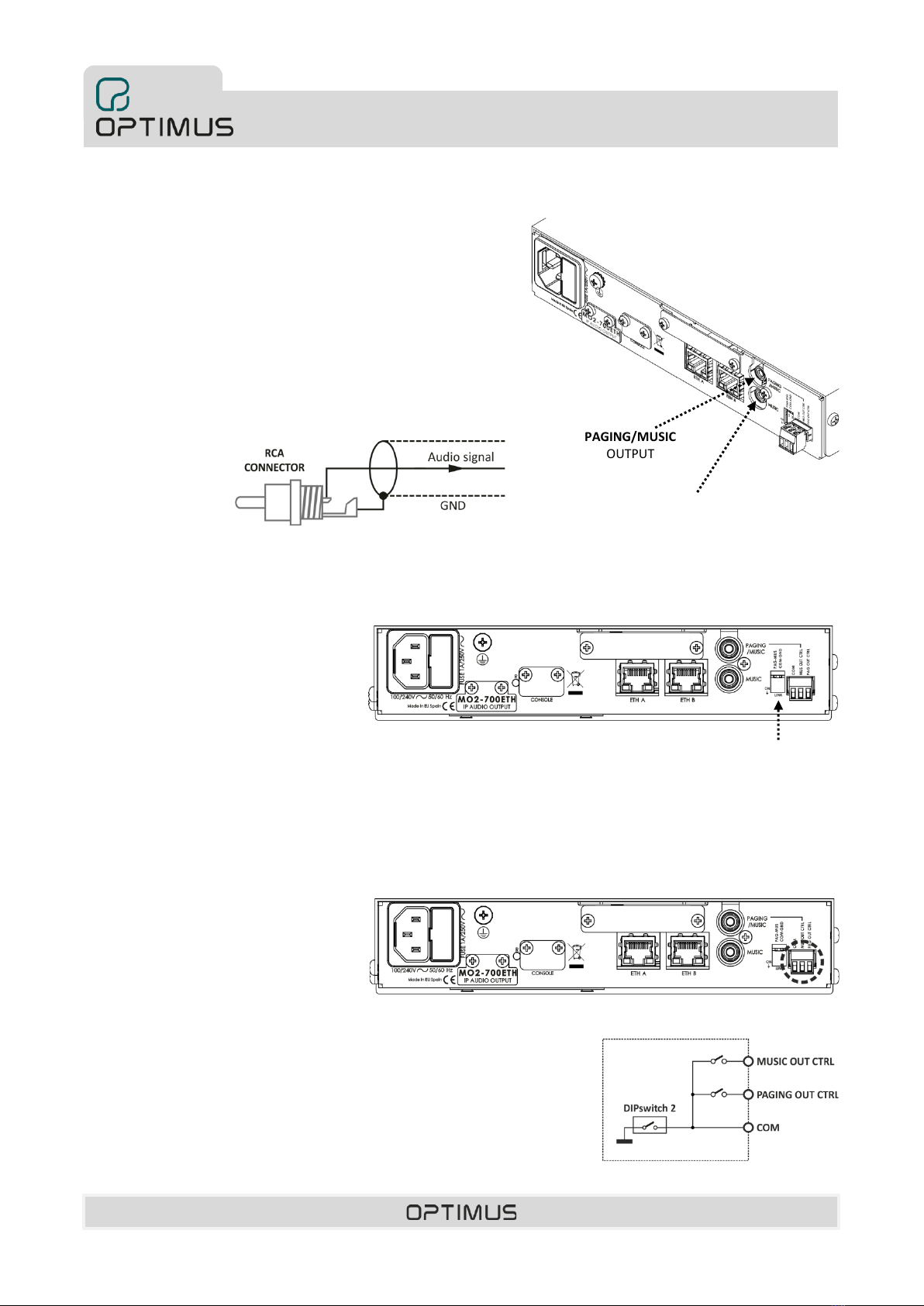
•Two analog outputs (music and music/announcements)
through RCA connectors.
•Dual Ethernet connection for installations with redundant
network systems. The connection is constantly monitored
and switches automatically if necessary.
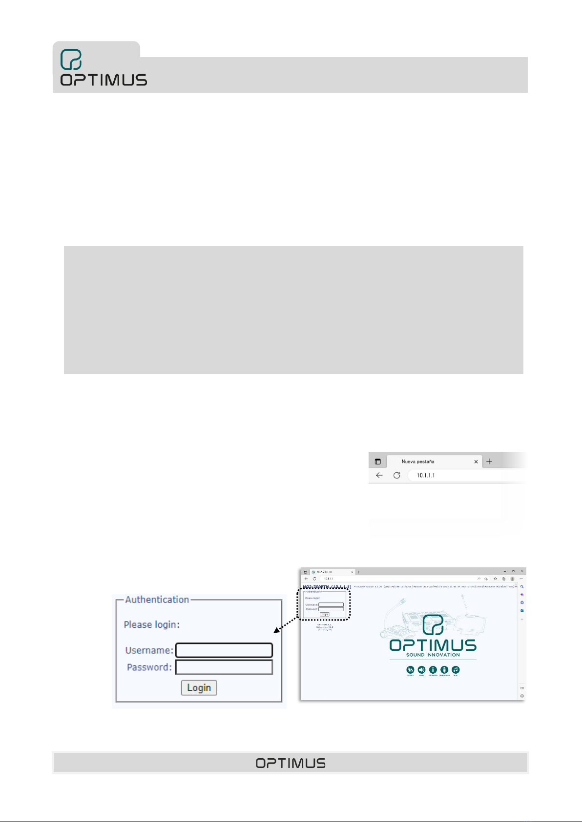
•IP address, gateway and netmask stored in flash memory.
•Active channel output contacts (one per channel).
•Indicator lights for:
-SIGNAL OUT: presence of analog signal at the
outputs.
-STREAMING: IP audio reception indicators.
-POWER: Power supply.
-STARTING/RUNNING, indicating the status of the
internal processor of the device (starting up or ready
and running).
-GENERAL FAULT: System alarm indicator.
-ETHERNET A and B connection status (LINK and
ACTIVITY).
•USB connection for system monitoring.
•Supervision of device operation through Call Point
software and/or basic TELNET or SSH (Secure Shell)
functions.
•Full range power supply (100-240Vac 50/60 Hz).
•Device of one unit of height and half width in 19" rack.
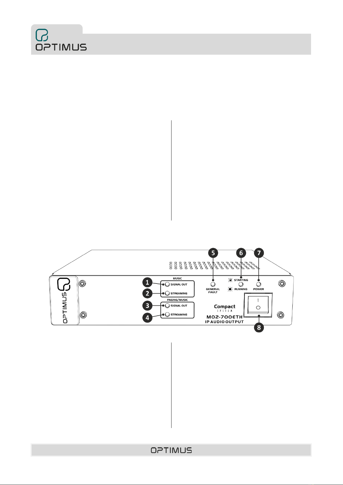
2. FRONT VIEW
(1) SIGNAL OUT indicator of the MUSIC CHANNEL.
Blue LED indicating the presence of analog signal at the
MUSIC output. It blinks following the audio signal level.
(2) STREAMING indicator of the MUSIC CHANNEL.
Yellow LED Indicator of active music channel.
(3) SIGNAL OUT indicator of the PAGING/MUSIC CHANNEL.
Blue LED indicating the presence of analog signal at the
PAGING/MUSIC output. It blinks following the audio
signal level.
(4) STREAMING indicator of the PAGING/MUSIC CHANNEL.
Yellow LED Indicator of active paging channel.
(5) GENERAL FAULT indicator.
Yellow LED indicator of alarm in the system.
(6) STARTING/RUNNING indicator.
Green LED. Flashes during device startup. When lit
steadily, it indicates that the device has finished the start-
up process and is now operational.
(7) POWER indicator.
Indicates that the device is powered.
(8) ON/OFF switch
Figure 1

MO2-700ETH 5.2.02 Version R+D Department 5
MO2-700ETH
IP receiver with one music
output and one paging output
3. REAR VIEW
1) Power supply input 100-240Vac 50/60 Hz. It allows the
connection of the device to the mains by means of the
supplied cable (CEE7 Male / C13 Female, 1.8m).
2) Mains power fuse (1A). There is a spare fuse inside the
same box.
3) Grounding.
4) RESET button. Clears the settings and restores the default
network address:
IP ADDRESS: 10.1.1.1.1
NETMASK: 255.0.0.0.0
GATETEWAY: 0.0.0.0.0 (no Gateway)
To do this, press and hold it for 10 seconds with the unit
turned on (the front STREAMING indicators will blink 4
times at the end of the process).
5) CONSOLE connector. Mini USB connector. Allows to
monitor the system. Specialized personnel only.
6) ETH A connector. Used to connect the device to the IP
network.
(6a) LINK indicator (yellow LED):
Indicates connection to the network.
(6b) ACTIVITY indicator (green LED):
Flashing indicates sending or receiving data.
7) ETH B connector. Used, in a redundant network, as a
secondary connection to the IP network.
8) PAGING/MUSIC connector. Audio output of the paging
channel.
By setting DIP switch 1 to ON, this paging output also
becomes the music channel output, so that it emits the
music channel while no paging is received. For its
connection see section 5.4.
9) MUSIC connector. Audio output of the music channel. For
its connection see section 5.4.
10) Configuration DIP switch.
DIP switch 1 PAG-MUS
In OFF position, the PAGING/MUSIC connector is used
only as paging output (PAGING).
In ON position, the PAGING/MUSIC connector is used
as paging and music output.
DIP switch 2 COM-GND
Connects (ON position) or separates (OFF position) the
COM contact of the terminal strip to the GND of the
device.
11) Output contacts. For their connection follow section 5.6.
COM. Common.
MUS OUT CTRL. It is activated when the music channel
is active.
PAG OUT CTRL. Activated when the paging channel is
active.
Figure 2

MO2-700ETH 5.2.02 Version R+D Department 6
MO2-700ETH
IP receiver with one music
output and one paging output
Safe handling with batteries:
•Warning! Improper use of battery may lead to explosion. Replace the batteries with the same or equivalent type only.
•Batteries may endanger life if swallowed. If a battery is swallowed, seek medical assistance immediately.
•Before inserting the batteries, check whether the contacts in the device and batteries are clean and, if necessary, clean
them.
•Only use new batteries.
•Do not use rechargeable batteries
•Never try to recharge normal batteries. There is a risk of explosion!
•Never expose batteries to heat sources (e.g. radiators) or direct sunlight. There is an increased risk of leakage!
•Never short-circuit the batteries.
•Never throw batteries into a fire.
•Do not disassemble or deform batteries.
•If the equipment is not going to be used for long periods, remove the battery.
•Remove leaking batteries from the device immediately. If battery acid leaks out it is essential to avoid contact with the skin,
eyes and mucous membranes! If the acid does come into contact with skin, immediately rinse the affected areas with plen-
ty of clear water and consult a doctor immediately. There is a risk of acid poisoning and acid burns!
•Remove exhausted rechargeable battery from the device immediately! There is an increased risk of leakage.
•Do not throw used batteries into the household waste. The batteries must be deposited in a collection point for used bat-
teries.
4. PLACEMENT OF THE BATTERY
The unit incorporates a RTC (Real-time clock) whose function is to maintain the current time. In order to keep the RTC powered even
if the unit is turned off, a 3V lithium battery type CR2032 supplied with the unit must be inserted.
It is advisable to replace the battery of the device at least every 5 years.
Battery placement procedure.
1) Disconnect the power supply to the device.
1)

MO2-700ETH 5.2.02 Version R+D Department 7
MO2-700ETH
IP receiver with one music
output and one paging output
2) At the bottom of the unit, unscrew the cover to access the battery holder.
3) Insert the battery respecting the polarity
indicated in the drawing.
4) Screw the cover back on and
connect the power supply.
2)
3)
4)

MO2-700ETH 5.2.02 Version R+D Department 8
MO2-700ETH
IP receiver with one music
output and one paging output
5. CONNECTION
5.1.Power supply
The device has a 100-240Vac 50/60 Hz power supply input that allows the
connection to the mains by means of the supplied cable (CEE7 Male / C13
Female, 1.8m).
5.2.IP Connection
Use the ETH A port (RJ45 connector) and Cat 5e FTP cable to connect the
device to the IP network.
5.3.IP Connection in installations with redundant
Ethernet network
In installations with network redundancy, use the ETH A and ETH B ports
(RJ45 connectors).
Ethernet connection
to switch 1
Connection to
Ethernet switch
Ethernet connection
to switch 2
Figure 4
Figure 5
Figure 3

MO2-700ETH 5.2.02 Version R+D Department 9
MO2-700ETH
IP receiver with one music
output and one paging output
MUSIC
OUTPUT
PAGING/MUSIC
OUTPUT
5.4.Connecting the audio outputs
The equipment has two audio outputs through RCA connectors:
•MUSIC output: audio output of the music channel.
•PAGING/MUSIC output: Audio output of the paging channel. By
setting DIP switch 1 to ON, this paging output also becomes the
music channel output as long as no paging is sent.
Through the Call Point or Call Point Configurator software the volume
of each output can be adjusted. Maximum output level = 0dBm.
Follow figure 7 for connection.
5.5.DIP switches configuration.
DIP switch 1 PAG-MUS.
In OFF position, the PAGING/MUSIC
connector is used only as paging output
(PAGING). In ON position, the
PAGING/MUSIC connector is used as paging
output and music output (PAGING/MUSIC).
Factory setting: OFF
DIPswitch 2 COM-GND
Connects (ON position) or disconnects (OFF
position) the COM contact of the terminal
strip to the GND of the device. Factory
setting: ON
5.6.Output Contacts
The unit has two output contacts:
-MUS OUT CTRL is activated when the
music channel is active.
-PAG OUT CTRL is activated when the
paging channel is active.
They are dry or grounded contacts, depending on the position of DIP switch number 2
(OFF= Dry contacts, ON= Grounded contacts).
ATTENTION: Max. DC load current: 150 mA.
Max. DC or AC peak load voltage: 350V.
MO2-700ETH
Figure 6
Figure 7
DIP switches
configuration
Figure 9
Figure 8
Figure 10

MO2-700ETH 5.2.02 Version R+D Department 10
MO2-700ETH
IP receiver with one music
output and one paging output
6. COMMISSIONING OF THE DEVICE
To commission the MO2-700ETH we must send configurations to it via an Ethernet connection. Accomplishing this requires a PC
equipped with a network card and connected to the MO2-700ETH through a switch or directly using a network cable. The PC must
have the configuration software installed.
1. Make the connections between the devices.
2. Turn on the power supply to the devices.
3. Use the Call Point or Call Point Configurator software to configure the parameters of the MO2-700ETH and send the settings to
the device
6.1. Configuration of the MO2-700ETH network addresses
To change the default network settings of the MO2-700ETH do the following:
1. From the PC, open a browser, enter the IP address of the unit and press ENTER.
By default, the IP address is 10.1.1.1: The IP address range of the device and
those of the PC must match. If this is not the case, you must first change the
network settings of the PC to bring it within the range of the device (e.g. the PC
could have the IP address 10.1.100.152).
2. Enter the user name optimax, the password 1933 and click on the Login button
ATTENTION. In order to be able to send configurations to the device, it is necessary that the device and the PC are
within the same IP address range. It is also necessary that the network addresses of the device and those set from the
configuration software match.
By default, the device’s network configurations are as follows:
IP ADDRESS: 10.1.1.1.1
NETMASK: 255.0.0.0
GATETEWAY: 0.0.0.0 (without Gateway)
If you wish to assign a different network address to the unit than the default one, follow the next section 6.1.
Configuration of the MO2-700ETH network addresses.

MO2-700ETH 5.2.02 Version R+D Department 11
MO2-700ETH
IP receiver with one music
output and one paging output
3. Click on Network.
4. Modify the desired
network settings (IP,
Netmask and
Gateway) and click on
the Change Network
Settings button to
apply the changes.
The device will restart
automatically.

MO2-700ETH 5.2.02 Version R+D Department 12
MO2-700ETH
IP receiver with one music
output and one paging output
7. SYSTEM ALARMS
The unit has a GENERAL FAULT indicator light (front yellow LED) that lights up when the unit receives one or more alarms from the
system or when it generates an alarm itself.
8. TECHNICAL SPECIFICATIONS
Ethernet communication
2 Ethernet connections (RJ45) A and B for redundant installations. IP Layer 3 & Layer 4
Network.
Audio outputs
1 output channel for music, via RCA by means of RCA connector.
1 output channel for paging or paging/music, by means of RCA connector.
Maximum output level: 0 dBm
Output contacts
2 output contacts, configurable as dry contacts or referenced to ground. Max. DC load
current: 150 mA. Max. DC or AC peak load voltage: 350V.
MUS OUT CTRL. Activated when the music channel is active.
PAG OUT CTRL. Activated when the paging channel is active.
Power supply
100-240 V.a.c.
Consumption
10W
LED indicators
SIGNAL OUT: Indicates presence of analog signal at the outputs.
STREAMING: IP audio reception indicators.
POWER: Power supply.
GENERAL FAULT: System alarm indicator.
STARTING/RUNNING, indicating the status of the internal processor (starting up or
ready and running).
ETHERNET LINK and ACTIVITY.
Weight
1.8 Kg
Finishes
Black painted iron RAL9005.
Dimensions (mm)
213.5 (width) x 44 (height) x 235 (depth)
Accessories (not included)
Z-120 Single 19" rack mount kit.
Z-122 Double 19" rack mount kit.
Z-111 DIN rail mounting kit.
Z-110 Wall mounting kit.

MO2-700ETH 5.2.02 Version R+D Department 13
MO2-700ETH
IP receiver with one music
output and one paging output
9. NETWORK SPECIFICATIONS
The COMPACT public address system allows audio and control data communication over Ethernet and IP networks.
Working at levels 3 and 4 of the OSI scale, the protocol allows communication through routers (IP protocol) by means of gateway and
subnet mask configurations. These features make it possible to work both at LAN and WAN level.
The protocols used allow to work without any problem in networks where the different public address systems are located in
different VLANs.
Communications it uses are:
TCP/IP for control communications between different devices.
UDP Unicast for the audio broadcasting from a local IP microphone to a local audio matrix (point to point communication).
UDP Multicast for the audio broadcasting from a global IP microphone to the audio matrixes (point to multipoint
communication).
VoIP: Audio matrix allows to work also like a receiving VoIP terminal (one call each time) as following standards:
-Call establishing according to SIP RFC 3261
-For zones selection --> DTMF through SIP INFO or RFC 2833
-Supports calls “Peer to Peer” or through Proxy server
-RTP audio (Unicast/Multicast)
-Supported audio codecs in VoIP calls:
G711 (µ-law + A-law)
G722
L16 (16 bits/44.1KHz)
For a properly operation as a VoIP terminal, network has to be configured according to the defined specifications for IP
telephony.
Ports for communications standard services used in COMPACT systems:
Protocol
Port
Others
TELNET
TCP (Unicast)
23
FTP
TCP (Unicast)
21
Ports for the SECURE communication services used in the COMPACT system:
Protocol
Port
Others
SSH
TCP (Unicast)
22
FTPS
TCP (Unicast)
990

MO2-700ETH 5.2.02 Version R+D Department 14
MO2-700ETH
IP receiver with one music
output and one paging output
For a COMPACT protocol operation, following parameters must be fulfilled:
Protocol
Multicast address
Port
Others
Control
TCP (Unicast)
10102,10103,10104
Unicast Audio (point
to point)
UDP (Unicast)
Between 6000 and 32000
Selected by configs.
Multicast audio
(point to multipoint)
UDP (Multicast)
Between 239.0.0.0 and
239.255.255.255
Between 6000 and 32000
Prefixed Multicast address-
es (static) for each global
sender. Selected by configs.
Configuration
UDP (Unicast)
10001
Configurations from PC.
Integration XML
TCP (Unicast)
27000
Integration to PC
(optional).
Integration JSON
TCP (Unicast)
28000
Direct integration and con-
trol to equipment.
Integration SNMP
UDP (Unicast)
161
162 (TRAPS)
Integration SIP
UDP (Unicast)
5060 (Control)
7078 (RTP Audio)
ICMP
ICMP (v4)
Check the communication of
the equipment in the instal-
lation.
It is strongly recommended to apply QoS policies (quality of service), both at the network level and at the equipment level, estab-
lishing priorities between the different types of traffic according to the following table:
Priority
Protocol
HIGH
Global Audio
UDP (Multicast)
Local Audio
UDP (Unicast)
Integration SIP
UDP (Unicast)
MEDIUM
TELNET
TCP (Unicast)
SSH
TCP (Unicast)
Control
TCP (Unicast)
Configuration
UDP (Unicast)
Integration XML
TCP (Unicast)
Integration JSON
TCP (Unicast)
Integration SNMP
UDP (Unicast)
LOW
FTP
TCP (Unicast)
FTPS
TCP (Unicast)

MO2-700ETH 5.2.02 Version R+D Department 15
MO2-700ETH
IP receiver with one music
output and one paging output
Backbone network specifications
-Bandwidth:
o3kbps of control data for each equipment and 1kbps additionally for each alarm.
▪Example:
Matrix with 5 alarms →3kbps (data) + (5 alarms * 1kbps) = 8kbps
Paging console with 2 alarms →3kbps (data) + (2 alarms * 1kbps) = 5kbps
Total data=13kbps
oStreaming audio channel according to the audio format protocol (configurable):
▪RAW PCM 48KHz / 16 bits: 768kbps for each audio channel.
▪RAW PCM 24 KHz / 16 bits: 384kbps for each audio channel.
▪RAW PCM 16 KHz / 16 bits: 256kbps for each audio channel.
▪RAW PCM 8 KHz / 16 bits: 128kbps for each audio channel.
▪RTP L16 RAW PCM 44KHz / 16 bits: 705.6kbps for each audio channel.
▪RTP G.711 µ-LAW 8KHz / 8 bits: 64kbps for each audio channel.
▪RTP G.711 A-LAW 8KHz / 8 bits: 64kbps for each audio channel.
-Note: Control (without alarms) + number of simultaneous channels * Type of format protocol = Bandwidth
oRAW PCM 48KHz, 4 channels, 100 equipment→(3kbps * 100Eq.) + (4CH * 768kbps) = 3.4 Mbps
oRAW PCM 48KHz, 4 channels, 50 equipment. →(3kbps * 50Eq.) + (4CH * 768kbps) = 3.2 Mbps
oRTP G.711 A-LAW 8KHz, 4 channels, 100 equipment.→(3kbps * 100Eq.) + (4CH * 64kbps) = 0.56 Mbps
oRTP G.711 A-LAW 8KHz, 4 channels, 50 equipment. →(3kbps * 50Eq.) + (4CH * 64kbps) = 0.4 Mbps
Switch/Router specifications for LAN and WAN networks
-Protocols:
oTCP/IP for control/signalization/status monitoring.
oUDP unicast for Local Audio.
oUDP multicast for Global Audio.
-Multicast snooping:
oMulticast filtering.
oIGMP v2.
-For large installations:
oMulticast Routing (Spanning Tree).
oCapable to handle TOS (Type of Service).

MO2-700ETH 5.2.02 Version R+D Department 16
MO2-700ETH
IP receiver with one music
output and one paging output
Network protocol stack
10.VERSIONES DE SOFTWARE Y FIRMWARE
Las funcionalidades descritas en este manual de usuario son válidas para versiones de software y firmware iguales o superiores a:
Firmware MO2-700ETH
Application version 5.2.26
Linux version 5.4.84
Software Call Point
Version 5.2.26
Software Optimax Flasher
Version .9333
11.DOCUMENT VERSION TRACKING
Reference system
Type of Document
Confidentiality
N/A
COMPACT/MO2-700ETH
Installation and operation guide
Rev
Date
Modifications Content
Written by:
5.2.001
January 2023
R+D Department
5.2.002
September 2023
i.MX6UL Processor
R+D Department
Approved By
Function
Date
Ferran Gironès i Puig
R+D Director
09/2023
(*) Direcciones Multicast y puertos reservados

MO2-700ETH 5.2.02 Version R+D Department 17
MO2-700ETH
IP receiver with one music
output and one paging output
12.WARRANTY
1. GUARANTEE CERRTIFICATE
1. OPTIMUS S.A. guarantees that its products are free from material and
manufacturing defects when they are first delivered to the purchaser.
2. In accordance with the conditions outlined here, OPTIMUS S.A. guarantees
its products for two (2) years from the date on which the purchaser acquires the
product. If, within this guarantee period, defects appear which are not due to
factors outlined in section 2, OPTIMUS S.A. shall replace or repair the unit using
equivalent, new or reconstructed replacement parts, as it deems fit. If
replacement parts are applied which improve the unit, OPTIMUS S.A. reserves the
right to charge the client for the additional cost of these components.
3. No guarantee benefits shall be provided other than those cited here.
4. In order to claim the guarantee rights, it shall be an essential requirement to
present the original purchase invoice or the guarantee certificate.
2. GUARANTEE PROVISIONS
1. In the event that the product had to be modified or adapted to comply with
local requirements concerning technical specifications or safety, and if the
country in question is not the country for which the product was originally
designed and manufactured, defects are not considered to be material or
manufacturing defects. Furthermore, the guarantee does not cover the execution
of these modifications or adaptations, regardless of whether or not they have
been carried out correctly.
Nor shall OPTIMUS S.A. be responsible for any costs under this guarantee for
these types of modifications.
2. The guarantee shall not entitle the purchaser to inspection or free
maintenance or repair of the unit, particularly if the defects are due to
inappropriate use. Nor do the guarantee rights cover defects in wearing parts that
become worn as a result of normal wear and tear. Wearing parts are, in
particular, potentiometers, switches/keys, and similar parts.
3. The guarantee does not cover defects in the equipment unit caused by:
•Abuse or incorrect use of the unit for purposes other than those for which it
is intended, in non-compliance with the service and maintenance
instructions specified in the Manual and/or Technical Instructions for the
unit.
•Connection or use of the product in a manner that does not correspond to
the technical or safety requirements of the country in which the unit is used.
•Installation in conditions other than those indicated in the Manual and/or
Technical Instructions.
•Deficiency or interruptions in the electricity supply or installation defects
which imply use in abnormal conditions.
•Damage caused by other equipment units that are connected to the product.
•The use or installation of Software (programmes), interfaces, parts or
supplies not provided and/or not authorised by OPTIMUS S.A.
•Failure to use the original packaging for transportation.
•Damage caused by force majeure or other causes not attributable to
OPTIMUS S.A.
4. The following elements are not covered by this guarantee:
•All plastic surfaces and all parts exposed to outdoor conditions which have
been scratched or damaged as a result of normal or abnormal use.
•Breakages, knocks, damage due to a fall or scratches caused by moving the
unit in any way.
•Damage caused by tests, use, maintenance, installation or inappropriate
adjustments, or as a result of any alteration or modification of any kind not
carried out by a Service Authorised by OPTIMUS S.A. in compliance with this
guarantee.
•Damage to persons or property that might be caused by the improper use of
the equipment, including lack of maintenance.
5. The guarantee shall not be valid whenever the following is observed:
•Amendments or corrections made to the details of the guarantee certificate
or purchase invoice.
•Failure to produce the original invoice or the absence of a date on this.
•Absence of the serial or batch number on the equipment.
6. The warranty does not cover travel for technical assistance, except for those
caused by incidents that occurred during the first three months.
7. In the case of personal computers, the guarantee will not cover the
elimination of computer viruses, the restoration of programmes damaged by
these or the reinstallation of the disk following its deletion.
8. The rights of this guarantee are invalidated if the product has been repaired
or opened by staff unauthorised by OPTIMUS S.A. or by the client himself.
9. If OPTIMUS S.A. were to establish before the client that the damage affecting
the unit does not entitle a claim to be made under the guarantee, the costs of
checking the equipment incurred by OPTIMUS S.A. shall be borne by the client.
10. Products not covered by the guarantee shall only be repaired once payment
has been effected by the client. In the event that the guarantee rights do not
apply, OPTIMUS S.A. shall duly inform the client. If, within a period of 6 weeks
from this communication, no written repair order is received from the client
confirming acceptance of the costs, OPTIMUS S.A. shall return the unit in question
to the client. In this case, the transport and packaging costs shall be invoiced
separately and payment shall be made on delivery. In the event that a repair
order is sent by the client, confirming that he assumes the costs of repair, the
transport and packaging costs shall be invoiced additionally, and also separately.
11. If the equipment needs to be transferred to the Authorised Service Centre,
transportation shall be effected by the responsible party according to the
guarantee, who will also bear the freight and insurance costs.
12. In the event of a defect, OPTIMUS S.A. guarantees that the repair and/or
replacement of parts so that the unit operates correctly will be made within a
period of no more than 30 days. Nevertheless, OPTIMUS S.A. would like to clarify
that the normal period does not exceed 30 days.
13. All parts or products replaced as part of the guarantee services shall become
the property of OPTIMUS S.A.
3. TRANSFER OF GUARANTEE
The guarantee is solely awarded to the original purchaser (principal client) and is
not transferable. With the exception of OPTIMUS S.A., no third party (dealers,
etc.) is authorised to award additional guarantees on behalf of OPTIMUS S.A.
4. CLAIMS FOR DAMAGE
In the event that OPTIMUS S.A. cannot provide a suitable guarantee service, the
purchaser shall not be entitled to claim any indemnity for damages arising. The
responsibility held by OPTIMUS S.A. is limited in all cases to the invoicing price of
the product.
5. RELATION WITH OTHER GUARANTEE RIGHTS AND NATIONAL LAW
1. This guarantee does not affect the rights of the purchaser with respect to the
vendor arising from the contract of sale accomplished.
2. These conditions of the guarantee provided by OPTIMUS S.A. are valid as long
as they do not contradict the corresponding national law on guarantee provisions.
3. OPTIMUS S.A. guarantees that this product complies with the safety regulations
in force in the country.
THIS LIMITED GUARANTEE DECLARATION IS THE EXCLUSIVE GUARANTEE OFFERED
BY OPTIMUS S.A. ALL OTHER EXPLICIT OR IMPLICIT GUARANTEES ARE EXCLUDED,
AND THIS ALSO APPLIES TO GUARANTEES OF MARKETABILITY AND SUITABILITY
FOR A PARTICULAR PURPOSE. (EXCEPT WHEN THESE GUARANTEES ARE REQUIRED
BY AN APPLICABLE LAW). NO GUARANTEE, EITHER EXPLICIT OR IMPLICIT, SHALL
BE APPLIED ONCE THE GUARANTEE PERIOD HAS EXPIRED
OPTIMUS S.A.
After-Sales Service
C/ Barcelona 101
17003 - GIRONA
Tel. 902 151 96 / 972 203 300
Fax. 972 21 84 13
e-mail:girona@optimus.es 1999/44/CE

9I347

v5.2.002

MO2-700ETH Versión 5.2.02 R+D Department 2
MO2-700ETH
Receptor IP con una salida de
música y una salida de avisos
INSTRUCCIONES DE SEGURIDAD
IMPORTANTE:
•Lea atentamente las instrucciones de seguridad.
•Guarde este manual para futuras consultas.
•Desenchufe el equipo durante las tormentas eléctricas y cuando no se vaya a usar durante un largo período de tiempo.
•Use siempre cables ya preparados para evitar riesgos de descargas eléctricas o fuego. En caso de tener dudas, consulte con un
instalador cualificado.
•No use el aparato en lugares húmedos o cerca de líquidos. No instale el aparato cerca de fuentes de calor. No bloquee los
orificios de ventilación.
•Cuando sea necesario, retire el polvo con un paño seco. No use disolventes como el alcohol. Mantenga el aparato limpio y sin
polvo.
•Se requiere personal cualificado para realizar todas las operaciones de mantenimiento.
Nota: La información proporcionada por este manual no incluye detalles de diseño, producción o variaciones en el equipo. Tampoco
incluye posibles situaciones de riesgo durante la instalación, funcionamiento o mantenimiento. Si usted necesita asistencia especial
más allá del manual, por favor contacte con nuestro servicio técnico
Table of contents
Languages:
Other Optimus Receiver manuals

Optimus
Optimus 2-Channel Professional Wireless Audio Link... User manual

Optimus
Optimus Professional STAV-3770 User manual

Optimus
Optimus STAV-3790 User manual

Optimus
Optimus 31-3042 User manual

Optimus
Optimus STAV-3680 User manual

Optimus
Optimus STAV-3590 User manual

Optimus
Optimus STAV-3580 User manual

Optimus
Optimus 12-174 User manual

Optimus
Optimus STAV-3780 User manual

Optimus
Optimus 31-3040 User manual