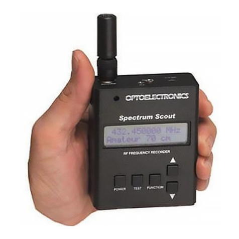
Optoelectronics M1 User manual

160 West Camino Real #233
Boca Raton, FL 33432
Telephone: 954-642-8997
Fax: 954-636-3533
Email: [email protected]
Internet: www.optoelectronics.com
®
OPTOELECTRONICS
© Copyright 2016 ptoelectronics, Inc.
U.S. atents
5,471,402 & 5,710,710

M1
USER MANUAL

Table of Contents
Introduction 4
Controls 5-6
peration 7
perating Modes 8-9
perational Characteristics 10
Signal Strength Bargraph 11
Display Resolution 12
Specifications 13 - 14
Antenna and Accessory Recommendations 15
Factory Service 16-17

CC
CAUTION
WARNING - Maximum input voltage is 12VDC. Automotive voltages may exceed 12V caus-
ing damage to internal circuitry. Damage resulting from excessive input voltage is readily
apparent and will not be covered under warranty. Units returned for warranty service that have
damage resulting from excessive supply voltages will incur service charges.
WARNING - Maximum antenna input signal is +15dBm (50mW). Under no circumstances
should the M1 be directly connected to an RF transmitter or be used in close proximity to a
radio transmitter of more than 5 watts. Damage to the input amplifier circuitry is readily appar-
ent and will not be covered under warranty. Units returned for warranty service that have dam-
age to the input circuitry will incur service charges.
This manual covers connection and operating instructions for the
Optoelectronics M1. The Optoelectronics M1 is covered under U.S.
atent Numbers 5,471,402 and 5,710,710.
!

4
The M1 is the latest advancement in hand-held frequency test instruments. It excels at finding and record-
ing frequencies for security, law enforcement, commercial and recreational applications. Patented tech-
nology developed by ptoelectronics employs statistical analysis to filter out actual radio transmission
frequencies from the background RF.
The M1 is more than a test instrument in the traditional sense because it is useful for finding frequencies
being used for two way radio communications. Designed to work with an antenna to pick up transmitted
radio frequencies, it is actually a frequency recorder. Up to 100 unique frequencies can be stored in mem-
ory. For in circuit measurement of frequencies from oscillators or test points, the 1Meg input impedance
amplifier can be used with a scope probe for direct connection to test points.
The counter circuitry produces a coherent and stable count when there is a single dominant signal 10 to
20 dB stronger than any other signal or the RF floor. An embedded microprocessor evaluates each mea-
surement statistically to determine when an actual RF frequency is dominant. This is the digital filter pro-
cessing which makes automatic capture and recording possible.
The M1 includes an AC-90 power adapter.
Introduction

OWER ON/OFF
To turn the M1 on press the Power N button. Upon power-up, an LCD self-test will be displayed
for two seconds. To turn the M1 off press the Power FF button.
GATE
The GATE button is used to change the measurement period of the M1. The GATE button is also
used to scroll forward through the M1’s 100 memories. To see the different GATE times for the M1
turn to the specifications page.
RANGE
The RANGE button is used to change the three different M1 ranges. A, B and Prescale. The RANGE
button is also used to scroll backward through the M1’s 100 memories.
1. A1Meg hm High Impedance Range: 1Meg hm range is indicated with a “A” in the top
right hand corner of the LCD. The frequency range of the 1Meg hm range is 50Hz-40MHz. This
range is useful for in-circuit measurement using a scope probe
2. B.50 hm Direct 250MHz Range: Direct range allows for the fastest count from 10 MHz-
250MHz. 50 hm Direct range is indicated with a “B” in the top right corner of the LCD.
3. rescale Prescale Range: Prescale range is used to count the frequency range from
30MHz-2.8GHz.
The 2.8GHz (Prescale) range completely covers all VHF and UHF communications so it is fine to
leave the M1 in this range all the time. The advantage of the direct 250MHz range is that it is much
faster to respond and it gives a measurement with more digits of resolution. If you are frequency
finding and do not know the range to look it is best to use the 2.8GHz range. If you know the
approximate frequency being transmitted is less than 250MHz then use the direct 250Mhz range.
Controls
5

6
Mode
The M DE button is used to select the different operating modes of the M1. When powered on the
M1 defaults to Normal mode. Normal mode is indicated by the oscillating digits on the LCD.
Pressing the M DE button once will activate Filter mode. Filter mode is indicated by “Filter” being
displayed on the top line of the LCD.
Pressing the M DE button again will activate Capture mode. Capture mode is indicated by
“Capture” flashing on the top row of the LCD.
Pressing the M DE button again will activate Recall mode. Recall mode is indicated by “Recall”
being displayed on the top row of the LCD.
CI-5
The jack labeled CI-5 on top of the M1 is used for interfacing to the ptoelectronics ptolinx for the
purpose of computer controlled operation or datalogging.
9-12VDC
The connector labeled 9-12VDC on top of the M1 is used for accepting the plug from the supplied
AC90 power adapter. The AC90 is a nominal 9VDC (9-12V) adapter. Plug the AC90 into the M1 to
charge the unit. A full charge will take approximately 8-10 hours. When using the internal NiCad
batteries as the power source the M1 will operate approximately 4-5 hours on a full charge.
Antenna
The BNC connector labeled antenna is used for a 50 hm antenna or 1 Meg hm scope probe.
Controls (cont.)

7
ptoelectronics frequency counters are unique in their ability to find RF transmission frequencies
quickly. Immediate response to frequencies that are 10 to 15 dB greater the the background RF floor
is possible. This is simply done by moving the M1 in the nearfield of the transmitter. The nearfield
is the area close to the antenna where the field strength is high but falling off rapidly as distance
increases.
Several factors may prevent a stable frequency counter reading even when there is a bargraph
response.
The signal is simply too weak. While the M1 is a very sensitive counter it does not react
well to extremely weak signals.
Amplitude Modulation (AM). Since the counter is measuring the zero crossings of the sig-
nal, it is sensitive to the amplitude of the received signal. AM signals such as TV video carriers, air-
craft radios, etc. can be difficult to count since their peak amplitude may be high enough to cause a
bargraph indication, but the valley is too low in amplitude for reliable counting. AM signals can be
very frustrating in this regard, looking like a signal that should easily count and yet never giving a
stable count.
Multiple signals. The M1 may not be able to separate adjacent carriers. The FM broadcast
band is a good example of this, a 20MHz wide band with channels on 200kH centers. In any city
numerous stations will exist within a given area. It is possible that none of the signals will be 10-
15dB higher than the rest which makes accurate counting difficult.
peration

8
Normal Mode
The M1 defaults to normal mode when powered on. Normal mode is indicated by the oscillating dig-
its on the LCD. In normal mode a frequency will be displayed as long as a signal is present. As soon
as the carrier drops the digits will resume oscillation. All three ranges (A, B, or Prescale) may be
selected during normal mode. Prescale range automatically corrects the Gate time and display..
Filter Mode
To enter filter mode press the M DE button until “Filter” is displayed in the top left hand corner of
the LCD. In this mode, the patented Digital Auto Filter is activated. Each time a frequency passes the
filter the red gate LED will flash and the display will update. The purpose of Filter mode is to reduce
random counting, noise and false signals. A unique filtering algorithm permits only meaningful mea-
surements to be displayed. All three ranges (A, B, or Prescale) may be selected during filter mode.
The gate time may be changed according to the range selected.
Capture Mode
To enter capture mode press the M DE button until flashing “Capture” is displayed in the top middle
portion of the LCD. In capture mode, the patented Digital Auto Capture is activated. Capture mode
is also where unique frequencies will be logged to one of 100 memories. Upon capture of a frequen-
cy, the red gate LED will flash once and the frequency will be displayed. At the same time the fre-
quency will be logged to memory. The corresponding memory location will be displayed to the left
of the frequency starting at 00 and ending at 99. The M1 will only log a unique frequency to a mem-
ory location. If the M1 captures the same frequency repeatedly it will not write those frequencies to
separate memory locations. All three modes (A, B, or Prescale) may be selected during capture mode.
perating Modes

Recall Mode
To enter recall mode press the M DE button until “Recall” is displayed on the LCD. The first memo-
ry location, (00), will be displayed along with the frequency logged to that memory. To scroll forward
through the frequencies in memory press the RANGE button. The next frequency in memory will be
displayed, up to 99. To scroll backward through the frequencies in memory press the GATE button.
Pressing and holding down either the RANGE button or GATE button will rapidly advance the memo-
ry location in the respective directions. Note: It is possible to scroll continuously in either direction.
Clear Memory
To clear the frequencies in memory press and hold down the mode button when turning power on.
perating Modes (cont.)
9

10
Multiple Transmissions
If two transmitters are operating at the same time within the pass band and they appear to have the same
signal strength, then the bargraph will display a strong signal indication but the counter display will not
stabilize. To compensate you must physically move closer to the transmitter of interest until the counter
sees its signal as 10-15dB greater in strength.
Strong Signal Overload
The M1 can be overloaded in the presence of a strong RF signal. In this situation the bargraph will also
display a strong signal indication. It may be necessary to reduce the signal level by moving away from
the transmitter or removing/shortening the antenna before the counter begins to count properly.
Multipath Cancellation
The distance at which the signal can be detected may be much greater than the distance at which it can
be counted. At 800MHz for instance the wave length is about 35cm and multipath cancellations can
repeat at very close intervals. As you decrease the distance the problem goes away. If you are in a vehi-
cle best results can be obtained when you come to a complete stop and the transmitter also stops motion,
providing a stable signal without multipath dropouts. Always operate the counter on the fastest mea-
surement time possible.
perational Characteristics

11
Signal Strength Bargraph
RF SIGNAL STRENGTH BARGRA H
The 16-segment bargraph display is a part of the M1 LCD front panel display which provides a
relative indication of RF signal strength. The bargraph indication at a given time does not neces-
sarily reflect the signal strength of the frequency shown on the display, rather an aggregate signal
level indication of all RF energy detected by the M1 at that instant. It is important to note that the
RF signal strength bargraph always provides a real-time signal level indication, whereas the fre-
quency display may show a frequency which was detected at some time in the past. The RF sig-
nal strength bargraph is ideal for uses such as the location of nearby transmissions and antenna
pattern testing.

12
Frequency Display Resolution
Least significant digit displayed (LSD) as a function of Gate Time and Range
Range Gate Time Meas. Time LSD Sample Display
250MHz 100us 13mS 10kHz 150.00
1mS 13mS 1kHz 150.000
10mS 13mS 100kHz 150.0000
100mS 110mS 10Hz 150.00000
1S 1S 1Hz 150.000000
10S 10S 0.1Hz 150.0000000
2.8GHz 6.4mS 13mS 10kHz 2000.00
64mS 75mS 1kHz 2000.000
640mS 640mS 100Hz 2000.0000
6.4S 6.4S 10Hz 2000.00000
Display Resolution

13
The M1 has the maximum amount of broad gain possible without driving the front end circuitry into hard
self oscillation. The purpose of this concept is to permit the maximum possible pick-up distance from radio
transmitters. There is no gain or sensitivity adjustment possible in the circuit. Specific sensitivities at par-
ticular frequencies are difficult to predict with precision in production units. The input sensitivity specifica-
tions below are intended to be a rough indication as to what may be expected. Defective components such
as blown amplifiers, broken or unsoldered chip resistors, capacitors and inductors will cause a drastic reduc-
tion in performance. These typical sensitivity specifications should not be relied upon for the purposes of
incoming inspection or evaluation. Contact the factory if the results obtained are significantly different than
those below. Performance on an antenna does not always relate exactly to input sensitivity as measured on
a signal generator. The purpose is to provide the best possible antenna performance regardless of sensitivi-
ty.
In ut Am lifier: 1Meg Ohm 50 Ohm
Im edance: 1Meg Ohm, 30pF 50 Ohm VSWR <2:1
Range: 50Hz-40MHz 10MHz-2.8GHz
Sensitivity: <20mV 1KHz-10MHz <10mV @ 10MHz
<50mV 10MHz-40MHz <1mV@ 150MHz
<7mV @ 800MHz
<12mV @ 1GHz
<100mV @ 2.8GHz
Maximum In ut: 50V AC + DC +15dBM, 50 milliwatts
Specifications

14
Time Between Measurements: 10 milliseconds, all range & gate times
Dis lay: 10 digit CD. Decimal at MHz point
Timebase: 10MHz setable to +/- 1ppm (Option 1ppm TCXO)
RF Signal Strength Bargra h: 16 segments, approximately 3dB segments, Relative
indication only
Size: 3.7” x H x 2.75”W x 1.2” D
Weight: 8.5 oz
Battery: Internal shrink wrapped 4 cell AA NiCad
O erating Time: Approximately 5 Hours
Charging Time: Approximately 8 hours
Power: 9-12VDC AC90 adapter supplied
Power Connector: 2.1 mm coax, center positive
Cabinet: Stamped aluminum with black painted finish
Specifications (cont.)

ANTENNAS
The small dual band, VHF/UHF, DB32 antenna is a very good multi-purpose antenna capable of pick-
ing up a very wide range of frequencies from 100MHz to 2GHz. There are other antennas available that
are useful for specific frequency ranges.
RD27 26-150MHz
RD150 144-165MHz
RD440 440-480MHz
RD800 500MHz-1GHz
RD2400 2400-2500MHz.
BB85 100MHz-2GHz
TA100S 100MHz-600MHz
FILTERS
The N100 FM broadcast notch filter will remove the influence from local FM stations.
SERIAL DATA INTERFACE
In order to download the memories of the M1, the ptoelectronics ptolinx serial data interface is need-
ed. The ptolinx universal PC interface adapts for use with a wide variety of receivers, frequency coun-
ters and frequency recorders for the purpose of computer control of a receiver and downloading memo-
ries of the M1. The ptolinx comes supplied with the CB-CI5 cable, which is necessary in order to inter-
face the M1 to the ptolinx for downloading.
Antenna and Accessory Recommendations
15

16
RODUCT WARRANTY
ptoelectronics, Inc. warrants all products and accessories for one (1) year against defects in materi-
als and workmanship to the original purchaser. Products returned for warranty service will be
repaired or replaced at ptoelectronics’ option.
Specifically excluded are any products returned under this warranty that upon examination, have
been modified, had unauthorized repairs attempted, have suffered damage to the input circuitry from
the application of an excessive input signal, have suffered damage to the charging circuitry or inter-
nal batteries from the application of excessive voltage, or show other evidence of misuse or abuse.
ptoelectronics reserves sole right to make this determination.
No other warranties are expressed or implied, including but not limited to the implied warranties of
merchantability and fitness for a particular purpose. ptoelectronics, Inc. is not liable for consequen-
tial damages.
WARRANTY
Products under warranty must be returned, transportation prepaid, to ptoelectronics’ service center.
All parts replaced and labor performed under warranty are at no charge to the customer.
NON-WARRANTY
Products not under warranty must be returned, transportation prepaid, to ptoelectronics’ service
center. Factory service will be performed on a time and materials basis at the service rate in effect at
the time of repair. A repair estimate prior to commencement of service may be requested. Return
shipping will be added to the service invoice and is to be paid by the customer.
Factory Service

17
RETURN OLICY
The ptoelectronics Service Department will provide rapid turnaround of your repair. A return
authorization is required. Enclose complete information as follows:
1. Copy of sales receipt if under warranty.
2. Detailed description of problem(s).
3. Complete return address and phone number (UPS street address for USA).
4. Proper packaging (insurance recommended). Note: Carriers will not pay for
damage if items are improperly packaged.
5. Proper remittance including return shipping, if applicable (Visa/MasterCard
number with expiration date, Money order, Company P , etc.). Note:
Personal checks are held for a minimum of two weeks before shipment.
Address all items to: ptoelectronics, Inc.
Service Department
160 West Camino Real #233
Boca Raton, FL 33432
If in question, contact the factory for assistance. Service Department: (954) 642-8997
Monday - Friday 8:30 AM to 5:00 PM Eastern Time.
Factory Service
Table of contents
Other Optoelectronics Test Equipment manuals