optofidelity OF-10030-00 User manual

OptoFidelity Oy • sales@optofidelity.com • www.optofidelity.com
OptoFidelity Video Multimeter
User Manual
Version 2018Q3.0

Page 2 of 51
OptoFidelity Video Multimeter – User Manual
©OptoFidelity 2013-2018
Microsoft and Excel are either registered trademarks or trademarks of Microsoft Corporation in
the United States and/or other countries.

Page 3 of 51
OptoFidelity Video Multimeter – User Manual
Contents
OptoFidelity Video Multimeter............................................................................ 1!
User Manual ................................................................................................... 1!
1!General information on OptoFidelity Video Multimeter ..................................... 6!
2!Start Window ............................................................................................ 6!
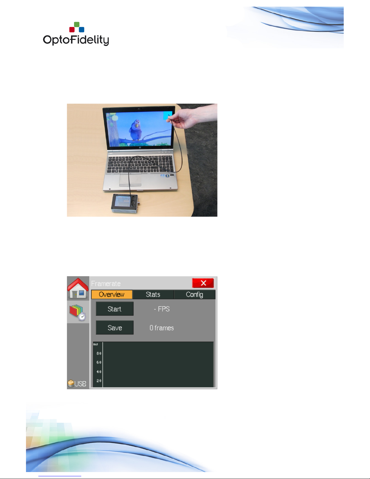
3!Frame rate measurement task ..................................................................... 7!
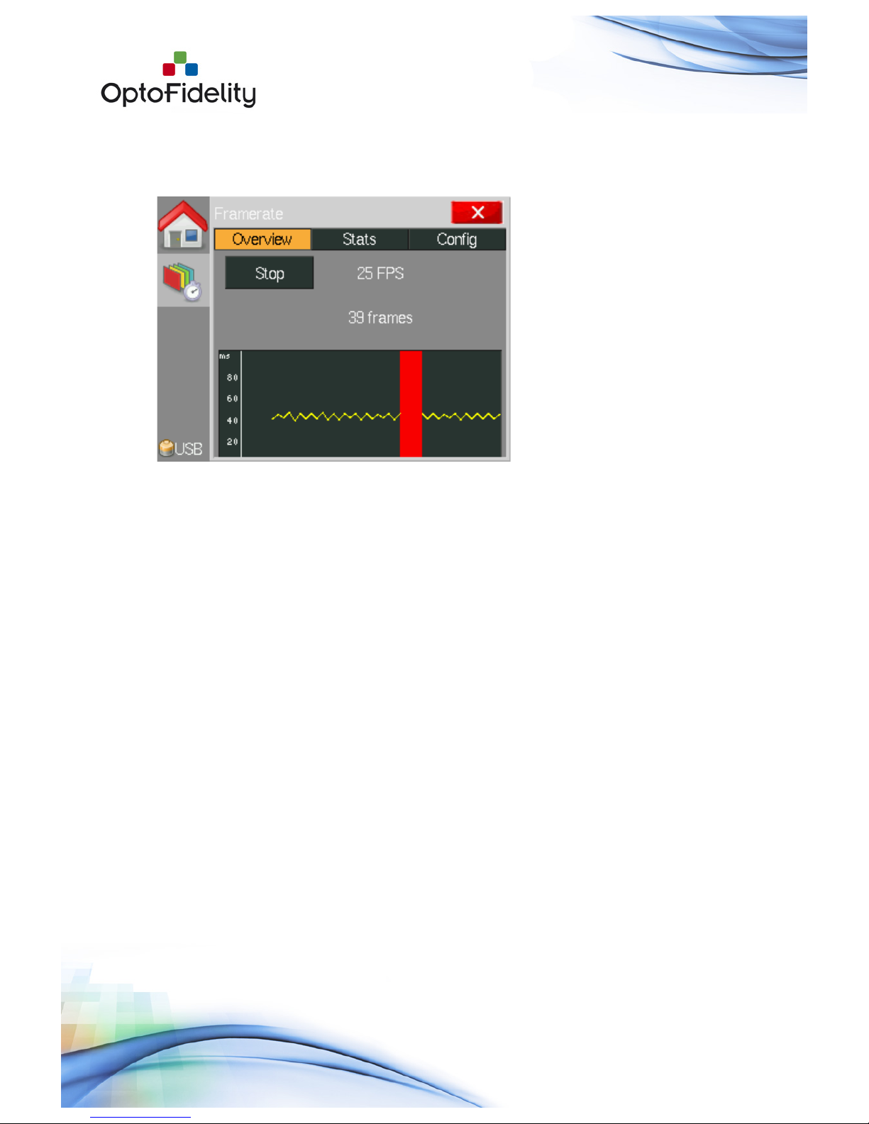
3.1!Overview tab ...................................................................................... 7!
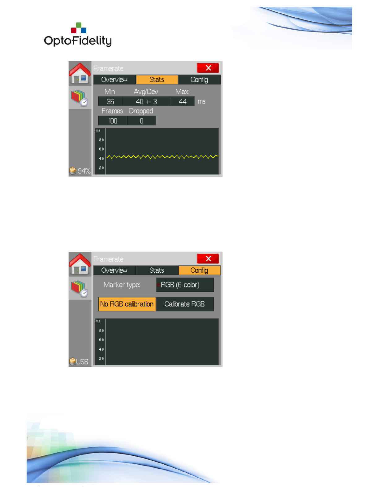
3.2!Statistics tab ...................................................................................... 9!
3.3!Configuration tab .............................................................................. 10!
3.4!Color calibration ................................................................................ 11!
3.5!Saved data files ................................................................................ 11!
4!Lip sync measurement option .................................................................... 12!
4.1!Option license activation..................................................................... 12!
4.2!Audio input cable connection............................................................... 12!
4.3!Framerate application’s Lip sync tab..................................................... 13!
4.4!Saved data files with Lip sync option.................................................... 15!
5!USB connection ....................................................................................... 15!
5.1!USB connection with Remote Control API.............................................. 16!
6!External trigger output option.................................................................... 17!
6.1!Option license activation..................................................................... 17!
6.2!External trigger configuration.............................................................. 17!
6.3!External trigger usage........................................................................ 18!
7!Camera viewfinder latency option............................................................... 18!
7.1!Option license activation..................................................................... 18!
7.2!Camera viewfinder latency measurement setup ..................................... 19!
7.3!Camera viewfinder latency measurement.............................................. 19!
8!Video Transfer Performance....................................................................... 21!
8.1!Video Transfer Performance Setup ....................................................... 21!
8.2!Video Transfer Performance Application................................................ 22!
8.3!Using Video Transfer Performance with recorded video ........................... 25!
8.4!Video Transfer Performance self-verification.......................................... 25!
8.5!Video Transfer Performance License Activation ...................................... 25!
9!Dual FPS (Frames per Second) option ......................................................... 26!

Page 4 of 51
OptoFidelity Video Multimeter – User Manual
9.1!Dual FPS option license activation........................................................ 26!
9.2!Dual FPS measurement setup ............................................................. 26!
9.3!Dual FPS measurement application ...................................................... 27!
9.4!Dual FPS Color calibration................................................................... 28!
9.5!Dual FPS measurement ...................................................................... 28!
9.6!Dual FPS result saving ....................................................................... 29!
9.7!Dual FPS Graph view ......................................................................... 30!
10!Measure VR Displays option ................................................................... 31!
10.1!Measure VR displays license activation ................................................. 31!
10.2!VR Display Measurement Setup ........................................................... 31!
10.3!Measure VR Displays application.......................................................... 32!
10.4!Measure VR Displays Measurement ...................................................... 32!
10.5!Measure VR Displays Save Function ..................................................... 34!
11!Mean Opinion Score (MOS) .................................................................... 35!
11.1!File view .......................................................................................... 35!
11.2!MOS score view ................................................................................ 35!
11.3!MOS Graph view ............................................................................... 36!
11.4!MOS Configuration (OptoFidelity default) .............................................. 38!
12!Measure Motion Blur option.................................................................... 40!
12.1!Measure Motion Blur license activation ................................................. 40!
12.2!Motion Blur measurement method ....................................................... 40!
12.3!Motion Blur measurement setup .......................................................... 42!
12.4!Motion Blur latency measurements ...................................................... 42!
12.5!Motion Blur latency results analysis & saving......................................... 44!
13!Timebase Calibration option................................................................... 46!
13.1!Timebase Calibration license activation................................................. 46!
13.2!Timebase Calibration application usage ................................................ 46!
13.3!Valid result for Timebase Calibration .................................................... 47!
14!Software update................................................................................... 47!
15!Technical specifications ......................................................................... 50!
16!References .......................................................................................... 51!
17!Change history..................................................................................... 51!

Page 5 of 51
OptoFidelity Video Multimeter – User Manual

Page 6 of 51
OptoFidelity Video Multimeter – User Manual
1 General information on OptoFidelity Video
Multimeter
OptoFidelity Video Multimeter is a compact desktop solution for measuring the true and
objective video playback performance of a mobile, tablet or any multimedia device
directly from the display of that device. It is controlled with a resistive touch display
which works best with, for example, a fingernail or stylus.
2 Start Window
When power is switched on the device starts and the Start Window opens. All installed
applications are listed in this window. You can browse the list by dragging or using the
arrow buttons on the right.
Figure 1: Start Window after turning on the device
Applications are classified according to their purpose:
• Measurement tasks: Measurement applications which are used to determine
some feature of the device under test (DUT).
• Utilities: General utility programs for using and configuring Video Multimeter.
• Result Analysis: Analysis of saved results.

Page 7 of 51
OptoFidelity Video Multimeter – User Manual
3 Frame rate measurement task
The frame rate measurement task determines the playback smoothness of the device
under test (DUT) with a test video. A blinking marker is measured from the display of
device and this marker helps to determine frame intervals and missing frames. The
basic measurement setup is shown in Figure 2.
Figure 2: Example of using Video Multimeter for frame rate measurement
3.1 Overview tab
When the Framerate measurement application is started, it opens with the Overview
tab shown in Figure 3. On this tab, you can start and stop measurements, have an
overview of the results and save them. The overview tab shows the average frames
per second (FPS) over the whole measurement and the total number of frames.
Figure 3: View of the Framerate application before measurement

Page 8 of 51
OptoFidelity Video Multimeter – User Manual
To begin a new measurement press the Start button. The measurement will start
immediately and continue until you press the Stop button. While the measurement is
ongoing the graph will scroll to show the results, as shown in Figure 4.
Figure 4: Frame rate measurement in progress
The vertical axis of the graph indicates the time that each frame is on the screen.
Readings on the vertical axis are in milliseconds, so for example a frame interval of 40
milliseconds equals a frame rate of 1/0.040 = 25 FPS. Dropped frames are shown as
red vertical bars, if they occur.
Note: To get repeatable results start and stop the measurement in the white period at
the start and end of the video. Such videos can be generated in OptoFidelity Test Video
Generator (TVG) by using the setting calibration=both.
After stopping the measurement, you can study the results on the Stats tab, or you
can save them using the Save button. After saving the results a message window shows
the name of the saved file, as shown in Figure 5. After the file is saved you can view
the Mean Opinion Score (MOS) of results in a separate application (See Chapter 10).
The application can be launched from Show MOS button (Figure 6) or from Start
Window.

Page 9 of 51
OptoFidelity Video Multimeter – User Manual
Figure 5: Message window after saving the measurement results
Figure 6. “Show MOS” button is available after the file is saved.
3.2 Statistics tab
During or after performing a measurement you can switch to the Stats (Statistics) tab
to see further information. The view is shown in Figure 7.

Page 10 of 51
OptoFidelity Video Multimeter – User Manual
Figure 7: Statistics tab
The upper row displays the minimum, average, standard deviation and maximum
values of the frame intervals. The lower row displays the total number of frames and
the amount of dropped frames.
3.3 Configuration tab
By default the application uses an RGB marker with built-in color calibration. This is
suitable for most measurements with LCD displays. For other kinds of displays
adjustments on the Config tab may be necessary.
Figure 8: Configuration tab
As shown in Figure 8 the Configuration tab allows the selection of marker type and
color calibration. The available marker types are:

Page 11 of 51
OptoFidelity Video Multimeter – User Manual
1. RGB (6-color): Marker with specific color sequence of 6 different colors. This
measures frame intervals and detects dropped frames.
2. Black & White: Black and white marker. A simple method for testing frame
intervals, but detecting dropped frames is not possible.
3. Any change: Any large change of color will be considered as a change of frame.
This marker type can measure frame intervals of any marker, but dropped
frames will not be detected.
The selected marker type must match the type of the marker in the test video used.
3.4 Color calibration
The functionality of the RGB marker depends on the color space of the DUT since the
RGB marker is based on colors. Default settings can be applied for most LCD displays,
but OLED displays and other display technologies may require calibration. You can
easily see that calibration is needed if red bars appear on the graph constantly. This
indicates that some colors have not been detected.
Calibration is performed as follows:
1. Position the fiber on a color marker on the display. The video must be running.
2. Press the Calibrate button on the Config tab. Calibration takes a few seconds
and the fiber must be kept still on the marker during this time.
3. The new calibration is valid immediately. If required you can do calibration again
or deactivate the calibration by pressing the No calibration button.
Note: Color calibration is only necessary for the RGB marker. It is not necessary and
cannot be successfully performed for other kinds of markers.
3.5 Saved data files
The saved data files from the frame rate measurement are in semicolon separated CSV
format. Each row corresponds to one frame and has the following columns:
A) Microsecond timestamp of the frame start.
B) Microsecond length of the frame (-1 for dropped frames).
C) Color of the marker in the frame.
D) Cumulative count of frames dropped since start of measurement.

Page 12 of 51
OptoFidelity Video Multimeter – User Manual
Figure 9: Data file saved from frame rate measurement
The CSV format is supported by Microsoft Excel and many other data analysis tools.
4 Lip sync measurement option
When activated the frame rate measurement task shall contain an additional tab for lip
synchronization (Lip sync) measurement. The lip sync measurement option measures
the audio leading/lag values in milliseconds. This feature requires audio input, which is
implemented by connecting a 3.5mm audio jack to the Video Multimeter’s Sensor
interface.
4.1 Option license activation
The Lip sync option is activated by copying a valid license file into the Video
Multimeter’s SD card. The license file name is “Lip sync.ini”, and it should be copied
into folder /frm/license/. The file contents is as follows (an example):
; OptoFidelity Video Multimeter license file
; Device serial number: 5
; Feature name: Lip sync
[License]
salt = 1706318843
key = 2287536893
expire = 0
The device serial number must match the physical Video Multimeter device. License
files are generated by OptoFidelity only. License files should not be edited manually.
4.2 Audio input cable connection
This feature requires an audio input. A 3.5mm audio jack cable must be connected to
Sensor 1 interface. NOTE: The Lip sync feature is activated only if the audio cable is
physically connected to Video Multimeter before powering it up.

Page 13 of 51
OptoFidelity Video Multimeter – User Manual
Figure 10: Lip sync audio cable connected to Sensor 1 input
4.3 Framerate application’s Lip sync tab
When you have completed successfully the previous actions (valid license file copied
and audio cable connected), the Framerate task shows an additional tab in the Video
Multimeter UI as shown in Figure 11.
Figure 11: Framerate application Overview tab with lip sync feature activated
Additionally the Overview tab contains an indicator for momentary lip sync value. The
small blue marker in the graph shows the position where audio markers were detected.
The Lip sync tab contains tools for adjusting the audio level and indicators for
visualizing the lip sync measurement statistics.

Page 14 of 51
OptoFidelity Video Multimeter – User Manual
Figure 12: Lip sync tab's Audio volume indicator
The audio volume indicator value should be observed especially during the audio
markers. The ‘Marker detected’ indicator flashes with a blue color when the marker is
detected.
Statistics show the minimum, maximum, average and deviation for lip sync
measurements.
Figure 13: Lip sync tab's graph showing measurement statistics
The graph visualizes the statistical results. The square-shaped indicator’s width
corresponds to the deviation, and the location corresponds to the average value of lip
sync over the whole measurement. Minimum and maximum values are visualized by
small markers located at both sides of the square. The scale of the graph is -200...+200
milliseconds, where a negative value indicates that the audio was early.
Correspondingly a positive value indicates that audio was late.

Page 15 of 51
OptoFidelity Video Multimeter – User Manual
Graph scale colors (green, yellow, red) come from different standards and suggestions.
Limits, which are only instructive, are set as follows:
• Green (Good): within -15 … +45 ms (Acceptance limit according to ATSC IS-
191)
• Yellow (Moderate): within -45 … +125 ms (Human noticeable limit according
to ITU-R BT.1359-1)
• Red (Poor): over -45 … +125 ms (Human noticeable limit according to ITU-R
BT.1359-1)
It is important to understand that, for example, a moderate result does not necessarily
indicate that the measured video is perceived as bad. This is because the final user
experience also depends on the video content and watching context (large TV set
versus small mobile terminal). The above-mentioned standards and suggestions are
useful references when product/service–specific acceptance limits are defined.
4.4 Saved data files with Lip sync option
When the Lip sync feature is activated an additional column of results appears in the
results data file. The column is named ‘Lip sync (ms)’. The measured lip sync value is
printed at each detected ‘k’ frame (black color marker).
Figure 14: Data file saved from frame rate measurement, including lip sync
5 USB connection
Video Multimeter can be connected to a computer by a USB cable for battery charging
and data transfer. Charging will begin as soon as the USB cable is connected and is
indicated by a red LED next to the USB connector. When the battery is full, the LED
will turn off. Note that if the device is on, the LED will not turn off because power is
being used.

Page 16 of 51
OptoFidelity Video Multimeter – User Manual
Figure 15: USB mode selection screen
When the USB cable is connected and the device is on, a selection window such as in
Figure 15 opens on the display. The window has options Data transfer and Charge only.
If Data transfer is selected, the device will appear as a USB memory on the computer.
Other functions of the device will not be available while the data transfer is active.
Selecting Charge only will simply close the dialog so that the device can be used
normally while it is being charged.
5.1 USB connection with Remote Control API
If the Remote Control feature is activated on the device, the USB mode selection screen
has an additional choice:
Figure 16: USB mode selection screen with Control API feature activated

Page 17 of 51
OptoFidelity Video Multimeter – User Manual
By selecting Control API it is possible to control the device remotely via the USB
connection. Please refer to [1] for further information.
6 External trigger output option
Video Multimeter can be used to trigger external devices by the External trigger output
option. The physical BNC connector in the side of the device receives a controlled
trigger pulse each time Video Multimeter detects a frame change.
6.1 Option license activation
The External trigger option is activated by copying a valid license file into the Video
Multimeter’s SD-card. The license file name is ‘camera_trigger.ini’, and it should be
copied into folder /frm/license/. The file contents is as follows (an example):
; OptoFidelity Video Multimeter license file
; Device serial number: 5
; Feature name: camera_trigger
[License]
salt = 1706318843
key = 2287536893
expire = 0
The device serial number must match the physical Video Multimeter device. License
files are generated by OptoFidelity only. License files should not be edited manually.
6.2 External trigger configuration
The External trigger feature is active when the corresponding application is started
from the main menu. The Trigger camera on frames setup screen shows the
parameters that can be controlled:
Figure 17: External trigger output control application.

Page 18 of 51
OptoFidelity Video Multimeter – User Manual
The functions of this screen are as follows:
• Pulse length (ms):the length of the positive pulse in milliseconds that is
generated at the moment of a detected video frame
• Pulse delay (ms): the delay in milliseconds between the video frame detection
and the rising edge of the pulse
• Min. interval (ms): the time that Video Multimeter waits before outputting
new pulses when new video frames are detected
• Sensitivity: adjusts the sensitivity, meaning how small color changes are
considered as frame changes. For most cases, ‘Med.’ (Medium) sensitivity is
adequate.
• Backlight filter: controls whether the Video Multimeter’s automatic backlight
compensation is active or not. This feature speeds up the reaction time around
1ms. It is suggested that the display brightness is set to 100% if filter is off.
• Manual trigger: pressing this button generates a single pulse (for example,
for testing purposes)
6.3 External trigger usage
The external trigger feature is active when the Trigger camera on frames application
page is open. Other applications like Framerate can be used simultaneously.
Typical use case is to measure black/white marker with fiber. Color change indication
at BNC connector can be visualized with oscilloscope. Note that if other than
black/white marker types are measured there is significant delay from frame change
to BNC output signal.
7 Camera viewfinder latency option
The signal path from a digital camera to a display causes always some delay, typically
between 100 and 150 milliseconds. Less latency is always best, but the practical limit
for good user experience for sports/action photography is somewhere around 200
milliseconds.
Video Multimeter can be used to measure any device camera-to-display signal path
latency. These devices include smartphone cameras, tablets, pocket cameras and
DSLRs. Nothing prevents measurement of true end-to-end latency of IP camera-PC
setup as well.
7.1 Option license activation
The Camera viewfinder latency option is activated by copying a valid license file into
the Video Multimeter’s SD-card. The license file name is ‘viewfinder_latency.ini’, and it
should be copied into folder /frm/license/. The file contents is as follows (an example):
; OptoFidelity Video Multimeter license file
; Device serial number: 5
; Feature name: viewfinder_latency
[License]
salt = 1706318843

Page 19 of 51
OptoFidelity Video Multimeter – User Manual
key = 2287536893
expire = 0
The device serial number must match the physical Video Multimeter device. License
files are generated by OptoFidelity only. License files should not be edited manually.
7.2 Camera viewfinder latency measurement setup
The measurement setup is very simple; Video Multimeter shows a blinking marker,
which is captured by the camera of the device under test (DUT). The DUT display, for
example, a camera’s viewfinder, shows this blinking marker. Video Multimeter’s fiber
is then placed on the viewfinder display at the location of the marker.
The following diagram illustrates a typical setup:
DUT
Video)Multimeter
Fiber
Camera
Display
Display
Figure 18: Typical setup for measuring camera viewfinder latency
7.3 Camera viewfinder latency measurement
The measurement is activated by opening the Camera latency application from the
Main menu.

Page 20 of 51
OptoFidelity Video Multimeter – User Manual
Figure 19: Camera latency application just started
In the Camera latency application the marker (black-white) blinks at one second
intervals. The interval is fixed and enables the measurement of a latency of a maximum
of 500 milliseconds. Pressing the Clear button starts a new measurement. Statistics
are updated accordingly.
Figure 20: Camera latency application showing the measurement statistics.
The white text values show the instantaneous and most recent latency values.
Minimum, maximum, average and standard deviation values are shown as well.
Table of contents