DV11 / DVD100 / U2 / U3 1-1
Chapter 1
Introduction
1-1 Highlight
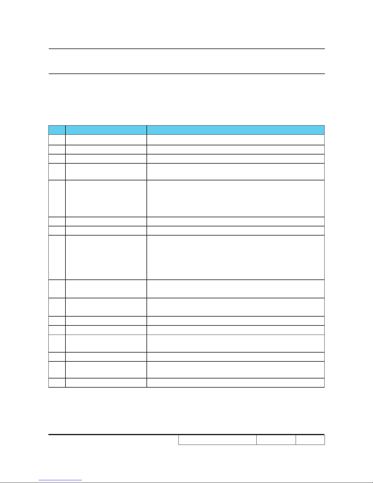
No Item Description
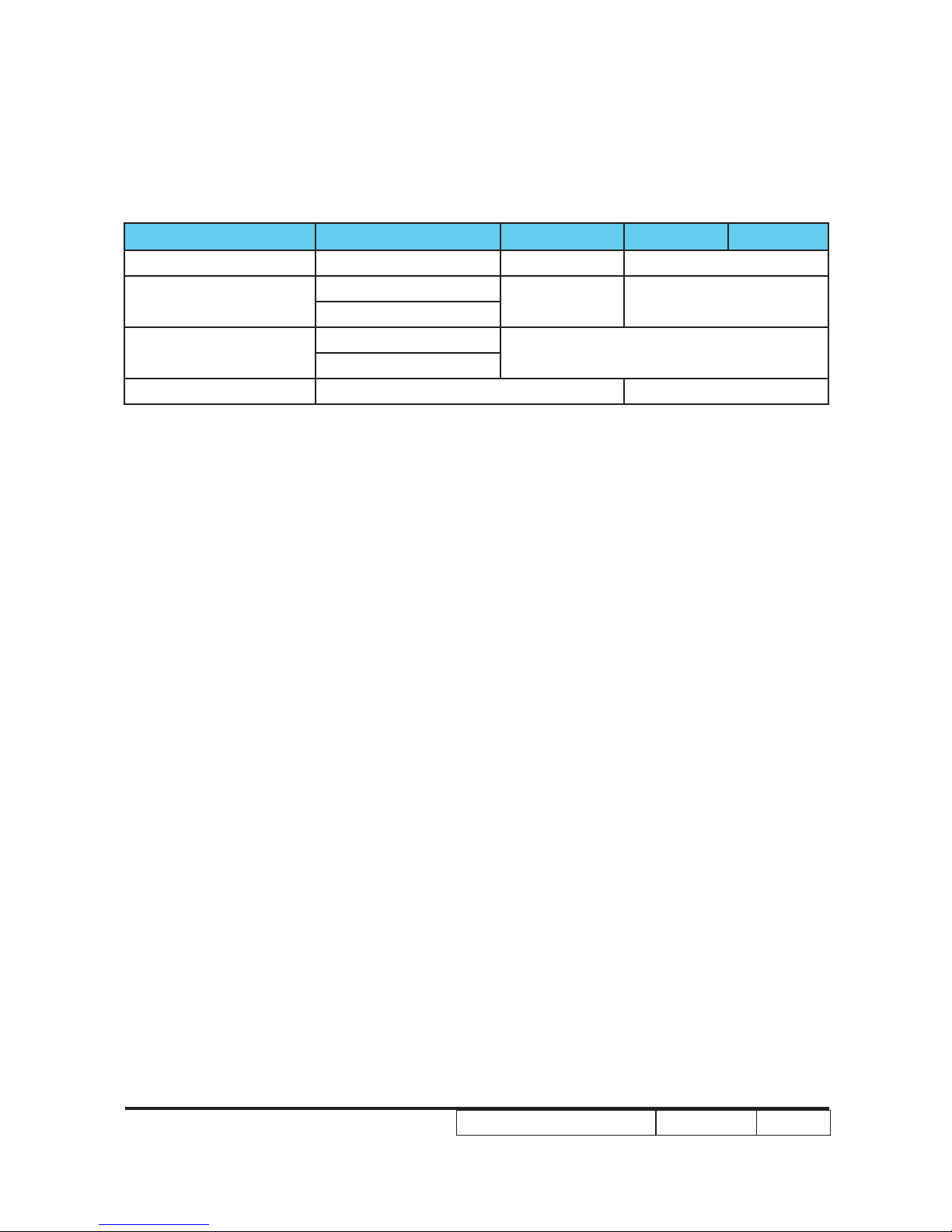
1 Dimensions (L x W x H)
2 Weight 8.3 lb
3 Tilt Angle
4 Power Supply
180W for Phoenix Lamp
5 Light source
Lamp could be changed by customer, but should follow the
user manual instruction.
Replaceable Lamp should be provided by Coretronic or its
6 Keystone correction
7 Color Pearl white for top and black for side and bottom
9 Cooling system
Advanced Air Flow
Two motor fans (one blower fan and one axial fan)
Temperature control circuits with adaptive voltage control
fan speed
Max touch temperature follows UL60950-1 regulation
10 Brightness Typical 1100 ANSI lm
Minimum 900 ANSI lm
11 Contrast Full on / Full off :Typical 1800 : 1
Minimum 1300 : 1 (Spoke on/Spoke off)
12 Uniformity
13 Throw ratio
14 Lamp door protection Lamp power supply shuts off automatically when door
open
15 Projection lens
16 Lamp life 180Watt Phoenix Lamp. Lamp life 1500 hours based on
17 System controller TI DDP2000

 User manual")