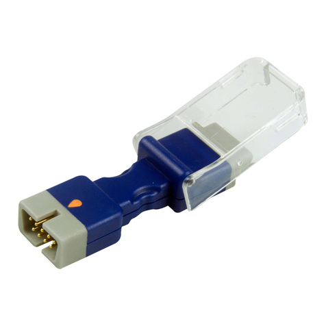
Orantech EtCO2 User manual

User Manual
EtCO2 Sensors
The dierence you can sense

2 3
Intended Use & Indications for Use
The intended use of the EtCOsensor is to provide carbon dioxide
monitoring to a host monitoring system during anesthesia/
recovery in the Intensive Care Unit (ICU) and in Emergency
Medicine/Transport or Respiratory Care.
Measurement Principle
The EtCOsensor uses an infrared absorption (IR) technique
for monitoring CO. The principle is based on the fact that CO
molecules absorb infrared light energy at specic wavelengths
with the amount of energy absorbed being directly related to
the COconcentration. When the IR light beam is passed through
a gas sample containing COthe electronic signal from the
photodetector can determine the levels of CO.
Storage & Handling
When not in use, sensors should be loosely coiled and stored at
room temperature. Don’t wrap sensors around equipment cases to
avoid damaging internal wires.

2 3
Operating Conditions
• Ambient temperature: 0°C to +40°C
• Relative humidity: 15% to 85%
• Atmospheric pressure: 86 kpa ~106 kpa
Storage & Packaging
Each sensor is individually packaged.
Sensors must be stored in their original packaging and within the
storage conditions to maximize the storage life.
Storage conditions are as follows:
• Ambient temperature: -10°C to +40°C
• Relative humidity: 15% to 85%
• Atmospheric pressure: 86 kpa ~106 kpa
Shelf Life
5 years.
Installation & Use
• Mainstream EtCO2Sensor

4 5
- Insert the EtCOSensor connector into the receptacle of the
host monitor.
- Choose the appropriate airway adapter and connect it to the
sensor head. The airway adapter clicks into place when seated
correctly (See gure 1).
- Set the sensor to zero.
- Install the airway adapter at the proximal end of the circuit
between the elbow and the ventilator Y-section (see gure 2).
Figure 1 Figure 2
• External Sidestream EtCO2Sensor
- Insert the EtCOSensor connector into the receptacle of the
host monitor.

4 5
- Connect the cannula, airway adapter, or sample line as
appropriate to the sensor. It will click into place when seated
correctly.
- Set the sensor to zero.
- For intubated patients requiring an airway adapter: Install the
airway adapter at the proximal end of the circuit between the
elbow and the ventilator Y- section (see figure 3).
- For intubated patients with an integrated airway adapter in
the breathing circuit: Connect the male luer connector on the
straight sample line to the female port on the airway adapter
(see gure 4).
Figure 3 Figure 4
- For non-intubated patients: Place the nasal cannula on the
patient (see gure 5).

6 7
Figure 5 Figure 6
- For patients prone to mouth breathing use an oral-nasal
cannula. For nasal or oral-nasal cannulas with oxygen delivery:
place the cannula on the patient as shown and then attach the
oxygen supply tubing to the oxygen delivery system and set the
prescribed oxygen ow (see gure 6).
Alarm Limits, Ranges and Default Settings
Refer to the User manual of the COmonitor intended to be used
with EtCOSensor.
Performance
Performance Parameter
Measurement
Technique
Non-dispersive infrared (NDIR) Infrared
spectroscopy

6 7
Initialization Time
Capnogram, displayed in less than 15 seconds, at
an ambient temperature of 25°C, full specications
within 2 minutes
COMeasurement
Range 0 to 150 mmHg, 0 to 19.7%
COResolution 0.1 mmHg 0 to 69 mmHg
0.25 mmHg 70 to 150 mmHg
COAccuracy
(0 ~40) mmHg ± 2 mmHg
(41 ~70) mmHg ± 5% of reading
(71 ~100) mmHg ± 8% of reading
(101 ~150) mmHg ± 10% of reading
Above 80 breaths per minute ±12% of reading
* NOTE: Gas temperature at 25°C
Respiration Rate
Range 0 to 150 breaths per minute (bpm)
Respiration Rate
Accuracy ± 1 breath(s) per minute (bpm)
Voltage
Requirements DC 5.0V ±5%
Temperature and
Humidity
Operating: 0°C to 40°C, 15% to 85% RH,
non-condensing
Storage: -10°C to 40°C, 15% to 85% RH,
non-condensing
Water Resistance IPX2 – Splash-proof (sensor head only)

8 9
• Interfering Gas and Vapour Eects
Gas or Vapor GAS Level Quantitative Eects
Nitrous Oxide 60 No additional eect
Halothane 4No additional eect
Enurane 5No additional eect
Isourane 5No additional eect
Sevourane 5No additional eect
Xenon 80
COvalue at 38 mmHg, the
maximum negative bias
Poor 5mmHg
Helium 50 No additional eect
Metered Dose Inhaler Propellants unspecied unspecied
Desurane 15
COvalue at 38 mmHg, the
maximum positive bias Poor
3mmHg
Ethanol 0.1% No additional eect
Isopropanol 0.1% No additional eect
Acetone 0.1% No additional eect
Methane 1% No additional eect

8 9
Cleaning and Disinfecting
• Unplug the sensor before cleaning or disinfecting.
• Dip clean the sensor part (not the connector) in a mild
detergent solution or a 70% isopropyl alcohol solution. If low-
level disinfection is required use a 1:10 bleach/water solution.
• Rinse the sensor part (not the connector) in water, wipe it with a
dry cloth and leave to dry completely.
Caution
Do not sterilize by irradiation steam, or ethylene oxide.
Warranty & Liability
Orantech oers 12 months warranty against defects in material or
workmanship from the date of purchase. But does not include the
damage or breakage due to the abusive use or negligent care of
the sensors.
Orantech reserves the right to perform warranty service at its
own facility. We guarantee that the products conform to the
specications of the safety and performance standards currently in

10 11
force and applicable to it.
Warning
• Before using the sensor conrm that the reading is set to zero. If
a non-zero reading is showing manually set to zero. Non-zeroing
may result in incorrect readings.
• Sensors are designed for use with specic monitors.
• The operator is responsible for checking the compatibility of the
monitor and sensor before use.
• Incompatible components can result in degraded accuracy and
performance.
• Consult the operation instructions for the equipment concerned
and the related accessories before operating equipment to
ensure their compatibility.
• Portable and mobile RF communications equipment can aect
the equipment.
• Do not use the sensor during MRI scanning. Conducted
current may cause burns on the patient. The sensor may aect
the MRI image, and the MRI unit may aect the accuracy of
measurements.
• Do not immerse sensor or sensor connector ends in cleaning
solution(s).

10 11
• Do not use sensor during transportation as this may case
measurement error.
Caution
Federal (U.S.) Law restricts this device to sale by or on the order of
a physician.
Waste Disposal
Please refer to your local laws and regulations for information on
how to dispose of EtCOsensors.
Title of Symbol
Manufacturer Caution
Date of manufacture
Catalogue number
Batch code
Serial number
Authorized
Representative
in the European
ACommunity
CE Mark

12
Protection against
vertically falling
water drops when
ENCLOSURE tilted up
to 150
Crossed out wheelie
bin indicates separate
treatment from
general waste at end
of life.
Waste of Electrical and
Electronic Equipment
Directive (WEEE)
Not made with
natural rubber latex
Non-sterile
Refer to instruction
manual / booklet
Type BF Applied
Part
Gas Port Input
Federal (U.S.) Law
restricts this device
to sale by or on the
order of a physician
Gas Port Output
REF: M20-M022
Rev: A0
Cables and Sensors B.V.
Zekeringstraat 21B 1014 BM Amsterdam, Netherlands
Orantech Inc.
Zone#A, 4F, 1st Bld, 7th Industrial Zone, Yulv Community, GongMing,
Guangming New District, Shenzhen, China 518106
www.orantech.com
Table of contents
Other Orantech Medical Equipment manuals
Popular Medical Equipment manuals by other brands

Laerdal Medical
Laerdal Medical SimMan 3G Quick setup guide

Nortech
Nortech AUTOLITH IEHL Quick Reference and Information Guide

Direct Supply
Direct Supply ATLAS owner's manual

Reliance
Reliance 7900 Installation and operating instructions

Bioventus
Bioventus EXOGEN user guide

Detecto
Detecto Detecto 8432-CH owner's manual