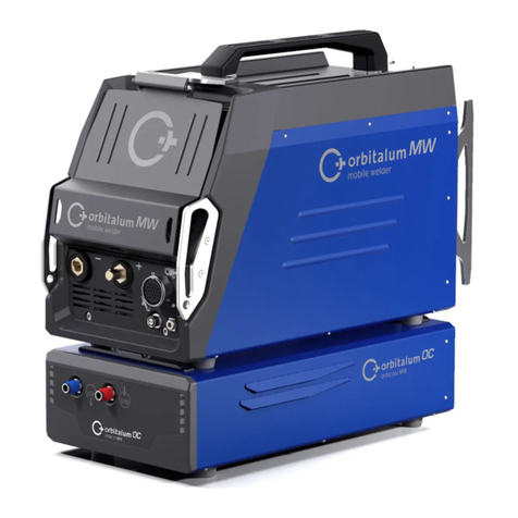
Orbitalum ORBIMAT CAdvanced Series User manual

Operating instructions
for operators and machine users
Orbital Welding Power Supplies
ORBIMAT CAdvanced
ORBIMAT 165 CA
ORBIMAT 300 CA
Machine No:
Please read all operating instructions before commissioning this machine so that you can work with it safely.
Retain the operating instructions for future use.

2 | orbitalum tools GmbH, D-78224 Singen, www.orbitalum.com, Tel. +49 (0) 77 31 792-0 (01.2012) OM_BA_ORBIMAT_CA_01_EN
ORBIMAT CA | Operating instructions
1. ABOUT THIS INSTRUCTIONS..................................4
1.1 Warnings ...................................................4
1.2 Other symbols and labels...........................4
1.3 Abbreviations ............................................4
1.4 Warning signs............................................5
2. OWNER INFORMATION AND
SAFETY PRECAUTIONS..........................................6
2.1 Duties of the owner....................................6
2.2 Use of the machine.....................................6
2.2.1 Intended purpose.............................6
2.2.2 Improper use ...................................6
2.2.3 Limits of the product ........................6
2.3 Basic safety precautions ............................7
3. LAYOUT OF THE PRODUCT...................................10
3.1 ORBIMAT 165 CA......................................10
3.2 ORBIMAT 300 CA......................................11
3.3 Integrated compact cooling* ....................11
3.4 Accessories .............................................12
3.4.1 ORBICAR W trolley with integrated
water coolant.................................12
3.4.2 ORBICOOL W..................................12
3.4.3 ORBICOOL Active ...........................12
3.4.4 ORBITWIN switching device............12
3.4.5 ORBICAR S trolley ..........................12
3.4.6 ORBTROLLEY..................................13
3.4.7 Durable carrying case ....................13
3.4.8 BUP Control Box.............................13
3.4.9 Oxygen meter ORB 1001 ................13
3.4.10 ORBIPURGE forming set..................13
3.4.11 CompactFlash Card 32 MB..............13
3.4.12 Soft-/Hardware package ................14
3.4.13Remote control with cable ..............14
3.4.14 Paper roll for integrated printer ......14
3.4.15 Ribbon cartridge for integrated
printer ...........................................14
3.4.16 Anti freeze .....................................14
4. CHARACTERISTICS AND RANGE OF
APPLICATIONS ...................................................15
4.1 Characteristics.........................................15
4.2 Additional characteristics.........................16
4.2.1 ORBIMAT 165 CA............................16
4.2.2 ORBIMAT 300 CA Compact .............16
4.2.3 ORBIMAT 300 CA AC/DC.................16
4.2.4 ORBIMAT 300 CA AC/DC Compact...16
4.2.5 ORBIMAT 300 CA AVC/OSC.............16
4.3 Functional description..............................16
5. TECHNICAL DATA ................................................17
5.1 System data.............................................17
5.1.1 Components and parts...................17
5.1.2 Technical Data ...............................17
6. COMMISSIONING ...............................................19
6.1 Checking scope of delivery.......................19
6.2 Scope of delivery .....................................19
7. SETUP AND ASSEMBLY .......................................20
7.1 Control elements......................................20
7.1.1 Overview of the main control
elements .......................................20
7.1.2 Connections and control elements on
the front panel ...............................20
7.1.3 Operating concept..........................21
7.1.4 Operation via the rotary knob.........22
7.1.5 Operation via push switches
(softkeys) ......................................22
7.1.6 Operation via an external keyboard 22
7.2 Connection of the power source................23
7.2.1 Connecting gas bottle and weld head
.....................................................23
7.3 Commissioning ........................................24
7.3.1 Adding anti-freeze and water..........25
7.3.2 Commissioning water pump ...........25
8. OPERATION........................................................29
8.1 Auto programming ...................................29
8.1.1 Setting parameters ........................29
8.2 Testing the procedure...............................31
8.2.1 Preparing weld head ......................31
8.2.2 Connecting forming gas .................32
8.2.3 Welding .........................................33
8.2.4 Interrupting the welding process ....34
8.3 Adjusting the procedure ...........................35
8.3.1 Reasons and steps for adjusting
procedure ......................................35
8.3.2 Making percental changes..............35
8.3.3 Adjusting individual parameters.....36
8.3.4 Adjusting gas times .......................36
8.3.5 Adjusting ignition current, end current
and current slope-off .....................37
8.3.6 Adjusting the pool formation time ..38
8.3.7 Adjusting welding current and
transition times ("Slope")...............38
8.3.8 Adjusting pulse times ................... 40
TABLE OF CONTENTS

(01.2012) OM_BA_ORBIMAT_CA_01_EN orbitalum tools GmbH, D-78224 Singen, www.orbitalum.com, Tel. +49 (0) 77 31 792-0 | 3
ORBIMAT CA | Operating instructions
All rights reserved, particularly the right to copy, distribute and translate. Duplication or reproduction in any form
(print, photocopy, microfilm or data capture) requires written permission from Orbitalum Tools GmbH.
8.3.9 Adjusting weld speed and transition
time ("Slope")............................... 40
8.3.10 Changing the sector .......................42
8.4 Saving and calling up a procedure ........... 44
8.4.1 Saving a procedure ....................... 44
8.4.2 Calling up a procedure .................. 44
8.5 Locking machine with key switch..............45
8.6 Tacking function...................................... 46
8.7 Using the second gas pressure level ("flow
force") .....................................................47
8.8 Connecting supplementary devices ..........47
8.8.1 ORB 1001 Residual Oxygen Meter...47
8.8.2 Connecting and configuring the BUP
control unit ................................... 48
8.8.3 TIG manual welding torch .............. 48
8.8.4 External remote control..................49
8.8.5 External printer (A4).......................49
8.8.6 External monitor/LCD (VGA)............49
8.9 Monitoring functions................................50
8.9.1 General information .......................50
8.9.2 Adjusting limit values.....................50
8.9.3 Grenzwerte anpassen ....................50
8.10 Data documentation and data management
...............................................................51
8.10.1 Managing data...............................51
8.10.2 Entering comments and application
data ("Process details") .................52
8.10.3 Working with external memory cards
.....................................................53
8.10.4 Viewing and printing data ..............54
8.10.5 Editing data on a PC with the
"OrbiProgCA" supplemental software
.....................................................55
8.11 Updating and backup functions for the
software..................................................55
8.12 Updating software components................56
8.13 Saving software components ...................56
8.14 Restoring software components ...............56
8.15 Working in other languages......................56
8.15.1 Changing the language ..................56
8.15.2 Printing data in another language...57
8.15.3 Creating a new operating language.57
8.16 Importing programs from other ORBIMATIC
power sources .........................................57
8.17 Special keyboard commands ....................57
8.18 Operation of the system with other mains
voltages (OM 165 CA only)........................58
9. SERVICE AND TROUBLESHOOTING ......................59
9.1 Performing service work...........................59
9.1.1 Pumping out water.........................59
9.1.2 Performing motor calibration..........59
9.1.3 Adjusting an external printer ........ 60
9.1.4 Switching on an internal printer..... 60
9.1.5 Printing a test page........................61
9.1.6 Service screen ...............................61
9.1.7 Info................................................62
9.2 Possible application/operating errors.......62
9.2.1 Uneven weld seam ("current
fluctuations") ................................62
9.2.2 Annealing colors inside/outside .....62
9.2.3 Wide seam and no weld penetration
.....................................................63
9.2.4 Uneven seam/hole formation at the
end of welding ...............................63
9.2.5 Ignition problems...........................63
9.2.6 Machine does not start ................. 64
9.3 List of error messages............................. 64
9.4 Status LED indicators .............................. 68
9.5 Temporarily deactivating sensors and
monitoring functions................................71
9.6 Setting date and time...............................72
10. MAINTENANCE, SERVICE AND REMEDYING ERRORS
.........................................................................73
10.1 Maintenance............................................73
10.1.1 Maintenance intervals....................73
10.1.2 Storage..........................................74
10.2 Service/Customer service.........................74
11. ENVIRONMENTAL PROTECTION AND DISPOSAL....75
11.1 Electric tools and accessories...................75
12. OVERVIEW WIRING DIAGRAM..............................76
13. EC DECLARATION OF CONFORMITY......................77
13.1 ORBIMAT 165 CA | 300 CA ........................77

4 | orbitalum tools GmbH, D-78224 Singen, www.orbitalum.com, Tel. +49 (0) 77 31 792-0 (01.2012) OM_BA_ORBIMAT_CA_01_EN
ABOUT THIS INSTRUCTIONS ORBIMAT CA | Operating instructions
1. ABOUT THIS INSTRUCTIONS
For quick comprehension of these instructions and safe handling of the machine, the warnings, notes and symbols
used in the instructions are presented here, as are their meanings.
1.1 Warnings
Warnings are used in these instructions to warn you of injury or damage to property.
XAlways read and heed these warnings!
This is the warning symbol. It warns you of the danger of injury.
XCarry out all measures identified with the safety symbol to avoid injury or death.
Warning symbol Meaning
DANGER
Immediate danger!
Non-compliance can result in death or very serious injury.
[Prohibited activities (if applicable).
XMeasures for avoiding danger.
WARNING
Possible danger!
Non-compliance can result in serious injury.
XProhibited activities (if applicable).
[Measures for avoiding danger.
CAUTION
Dangerous situation!
Non-compliance can result in minor injury.
XMeasures for avoiding danger.
CAUTION
Dangerous situation!
Non-compliance can result in damage to property.
XMeasures for avoiding danger.
1.2 Other symbols and labels
Symbol Meaning
Note: Include important information for comprehension.
Imperative: You must heed this symbol.
1. si Action instruction in a sequence of actions: You must carry out an action here.
XSingle action instruction: You must carry out an action here.
ZConditional action instruction: You must carry out an action here if the preceding
condition is fulfilled.
1.3 Abbreviations
Abbr. Meaning
OM ORBIMAT
CA CAdvanced

(01.2012) OM_BA_ORBIMAT_CA_01_EN orbitalum tools GmbH, D-78224 Singen, www.orbitalum.com, Tel. +49 (0) 77 31 792-0 | 5
ORBIMAT CA | Operating instructions ABOUT THIS INSTRUCTIONS
1.4 Warning signs
XHeed all warnings and safety precautions found on the machine.
The following information is also found on the machine:
Image Machine model Position on the
machine
Meaning Code No.
ORBIMAT 165 CA
ORBIMAT 300 CA
Rear Danger:
Danger of injury from
electric shock
-
ORBIMAT 165 CA
ORBIMAT 300 CA
Rear Warning:
Danger of injury from
electric shock
-

6 | orbitalum tools GmbH, D-78224 Singen, www.orbitalum.com, Tel. +49 (0) 77 31 792-0 (01.2012) OM_BA_ORBIMAT_CA_01_EN
OWNER INFORMATION AND SAFETY PRECAUTIONS ORBIMAT CA | Operating instructions
2. OWNER INFORMATION AND SAFETY PRECAUTIONS
2.1 Duties of the owner
• Workshop/outdoor/field use: The owner is responsible for safety in the dangerous area of the machine and ensures
that only trained personnel operate the machine and occupy the dangerous area.
• Employee safety: The owner is responsible for complying with the safety regulations described and for safety-
conscious working with all prescribed safety equipment see Sec. 2.3, Page 7.
2.2 Use of the machine
2.2.1 Intended purpose
The orbital welding systems (Power Sources CA/CB 165/300 and Orbitwin in conjunction
with the orbital weld heads of the OW/OWS/TP/P/OP/HX series and the accessories recom-
mended by the manufacturer) are used for the welding of ferritic, uncoated pipes up to the
pipe circumferences specified by the heads and maximum possible pipe walls using the
Tungsten Inert Gas process (TIG) with a direct current arc, and if specified, with an alterna-
ting current arc.
XHeed the safety precautions in these operating instructions.
XHeed the safety precautions in the operating instructions of the accessories and other
machines.
XComply with inspection and maintenance intervals.
XUse machine only in its original state. Use only genuine accessories, spare parts and
operating materials.
XDo not remove safety devices or modify their function.
XUse the machine only on empty, unpressurized pipes and containers in a non-
explosive atmosphere.
2.2.2 Improper use
Any use that differs from or goes beyond the use specified under "Intended purpose" is
improper. The owner shall be responsible for any damage which results from improper use.
The machine is not intended for use by the private consumer.
It is impermissible to remove safety devices or operate the machine without the safety
devices.
It is impermissible to exceed the technical values specified for normal operation..
2.2.3 Limits of the product
• Workplace: In pipe preparation, plant construction or in the plant
• Space requirement/Movement space: Radial space requirement of approx. 2 meters around the machine for
operating personnel.
• Working illumination: At least 300 Lux.
• Maintenance, see Sec. 10.1, Page 72
• Age of operating personnel: At least 14 years old and without physical impairments.
• Qualification of operating personnel: Instructed person with professional training in welding technology.
• Operation by one person
• Climate conditions:
Temperature range for machine operation: –10 °C to 40 °C, (< 70% rel. humidity).
Temperature range for machine storage: –20 °C to 40 °C, (< 70% rel. humidity).
XDo not work in misty, rainy or stormy conditions outside.
Cooling is only ensured with a full water tank.

(01.2012) OM_BA_ORBIMAT_CA_01_EN orbitalum tools GmbH, D-78224 Singen, www.orbitalum.com, Tel. +49 (0) 77 31 792-0 | 7
ORBIMAT CA | Operating instructions OWNER INFORMATION AND SAFETY PRECAUTIONS
2.3 Basic safety precautions
All products produced and sold by Orbitalum Tools GmbH are built for safe use using state-of-the-art technology.
Remaining risks are described in the following operating instructions. Using the equipment in a way other than as
described in the operating instructions can lead to serious personal injury and damage to property.
• Heed and comply with safety precautions.
• Store all documentation near the machine.
• Heed country-specific regulations, accident-prevention regulations, standards and guidelines.
• Use the machine only in proper operating order. Heed information on maintenance (see Sec. 10.1, Page 72).
• Report deviations in operating behavior of the machine to the person in charge immediately.
• Use only the dimensions and materials listed in these instructions. Other materials may only be used after
consulting with Orbitalum Tools customer service.
• Use only genuine tools, spare parts, operating materials and accessories from Orbitalum Tools.
• Repair and maintenance work on the electrical equipment may only be carried out by a qualified electrician.
• Switch the machine off, let it stop running and unplug the power plug after using it, before transporting it, before
changing tools and before carrying out cleaning, adjustment and repair work.
• Do not carry machine by the hose assembly. Protect machine cabling from heat, oil and sharp edges.
• Do not reach into the tools during operation.
• Ensure that the workpiece is clamped properly.
• Only switch on the machine if a pipe is clamped.
• When working with the machine, wear safety shoes as per EN ISO 20345 (at least S1).
• When working with the machine, wear safety shoes in accordance with EN ISO 20345 (at leastS1)
• In extreme usage conditions, conductive dust can settle inside the machine.
ZHave a professional electrician install an SPE-PRCD or ground-fault circuit (30 mA) between the mains
network and the machine.
The suggestions for "personal safety equipment" apply
exclusively and specifically for the product described.
Other requirements arising from ambient conditions at the
location of use, other products or the link with other products
are not taken into account.
These suggestions do not relieve the owner (employer) of his/
her legal duties regarding work-safety and health protection of
employees.
WARNING
Danger of system (Orbicar welding carriage, gas bottle, welding power source, cooling
unit) tipping over from the application of force from outside.
Various injuries and damage to property!
XSet up machine so that it also stands securely against external influences.
XKeep moving masses at least 1 meter away from the machine.
DANGER
Dangers of operation by multiple persons.
Various injuries and damage to property!
XHave one person operate the machine and weld head.

8 | orbitalum tools GmbH, D-78224 Singen, www.orbitalum.com, Tel. +49 (0) 77 31 792-0 (01.2012) OM_BA_ORBIMAT_CA_01_EN
OWNER INFORMATION AND SAFETY PRECAUTIONS ORBIMAT CA | Operating instructions
DANGER
Dangers of improper maintenance of the system.
Various injuries and damage to property!
XCarry out maintenance as described in the "Maintenance" chapter.
DANGER
Electrical hazards through touching and incorrect or damp safety equipment.
Electric shock!
[Do not touch energized parts (pipe), especially when igniting the arc.
[Do not allow persons with increased sensitivity to electrical hazards
(e.g. weakness of the heart) to work with the machine.
XWear dry safety shoes, dry metal-free (grommet-free) leather gloves and dry safety
suits to minimize the electrical hazard.
XWork on a dry surface.
DANGER
Accidental ignition.
Electric shock!
XSwitch off the orbital welding power source when connecting or disconnecting
a weld head.
WARNING
Electromagnetic incompatibility of surrounding devices during high-frequency ignition
and devices in operation without a protective ground.
Various injuries and damage to property!
XUse only electrical devices with protective insulation in the working area of the
welding system.
XObserve electromagnetically-sensitive devices when igniting the system.
WARNING
Ultraviolet radiation from the arc while welding.
Damage to eyes and burning of skin!
XDuring operation, wear eye protection as per EN 170 and skin-covering safety
clothing.
XWith closed weld heads, ensure proper working order of the eye protection.
WARNING
Hot leaking liquids and hot plug connections during heavy operation.
Danger of scalding!
XHeed the safety precautions of the technical supervisor/person in charge of safety.
DANGER
Incorrect handling of pressure tanks and other parts of the system
(e.g. forming gas bottle).
Various injuries and damage to property!
XHeed safety regulations, especially those for pressure tanks.
XComply with safety data sheets.
XIf the system and its components exceed 25 kg in weight, lift using several people or
lifting equipment.
DANGER
Flammable material near the welding zone or solvent in the room air.
Danger of explosion and fire!
[Do not weld near solvents (e.g. where painting is being carried out).
[Do not weld near explosive substances.
[Do not use flammable materials as a base in the welding area.
XEnsure that no flammable materials or soiling is located near the machine.
CAUTION
Hot surfaces of the weld head and weld points, including for a period of time after
welding.
Danger of burns!
XWear safety gloves.

(01.2012) OM_BA_ORBIMAT_CA_01_EN orbitalum tools GmbH, D-78224 Singen, www.orbitalum.com, Tel. +49 (0) 77 31 792-0 | 9
ORBIMAT CA | Operating instructions OWNER INFORMATION AND SAFETY PRECAUTIONS
WARNING
Poisonous vapors and substances during the welding process and handling of the
electrodes.
Health problems, including cancer!
XUse extraction devices as per the professional association regulations
(e.g. BGI: 7006-1).
XExtra caution is required with chrome, nickel and manganese.
[Do not use electrodes containing thorium.
DANGER
Faulty ignition in case of non-connected or incorrectly positioned weld head.
Electric shock, bodily injury and damage to property at other devices as well!
[Do not play with weld head.
XIf the weld head is not ready for operation, switch it to the "Test" function.
DANGER
Improper access to and opening of the ORBIMAT system.
Electric shock!
XDisconnect system from mains.
XDisconnect all external devices connected to the machine (weld heads etc.).
XAllow machine to cool down sufficiently before opening.
XAllow only a professional electrician to access the electrical system.
[Never connect an opened system to the mains network.
DANGER
Liquid in the housing due to improper use and transport.
Electric shock!
[Do not place liquids (drinks) on the system.
XDo not block ventilation slots.
XCheck housing interior for moisture after transporting the machine and leave it
open to air it out if necessary.
DANGER
Damaged plugs.
Electric shock!
[Do not use adapter plugs together with protectively grounded power tools.
XEnsure that the connecting plugs of the machine fit into the outlet.
DANGER
Catching of loose/long clothing, long hair or jewelry by rotating machine parts.
Very serious injury!
[Do not wear loose/long clothing, e.g. ties, when operating the equipment.
XSecure long hair against being caught.
DANGER
Defective safety parts due to soiling and wear.
Bodily injury due to failure of safety parts!
XReplace defective safety parts immediately.
XCheck safety parts daily for proper operation.
XCheck machine daily for externally visible damage and defects.
Have a professional remedy the damage and defects immediately.

10 | orbitalum tools GmbH, D-78224 Singen, www.orbitalum.com, Tel. +49 (0) 77 31 792-0 (01.2012) OM_BA_ORBIMAT_CA_01_EN
LAYOUT OF THE PRODUCT ORBIMAT CA | Operating instructions
3. LAYOUT OF THE PRODUCT
3.1 ORBIMAT 165 CA
9
1
2
3
4
5
6
7
8
10
11
1. Display housing
2. Printer cover
3. Intregrated Printer
4. Rotary knob
5. Multicard reader
6. Flowmeter
7. Front panel
8. Main switch
9. Hood
10. Softkeys
11. 10.5" color display
Fig. 1: Layout of Orbimat 165 CA

(01.2012) OM_BA_ORBIMAT_CA_01_EN orbitalum tools GmbH, D-78224 Singen, www.orbitalum.com, Tel. +49 (0) 77 31 792-0 | 11
ORBIMAT CA | Operating instructions LAYOUT OF THE PRODUCT
3.2 ORBIMAT 300 CA
4
6
7
8
9
10
11
5
2
3
1
1. Display housing
2. Printer cover
3. Integrated Printer
4. Rotary knob
5. Multicard reader
6. Flowmeter
7. Front panel
8. Main switch
9. Hood
10. Softkeys
11. 10.5" display
Fig. 2: Layout of ORBIMAT 300 CA
3.3 Integrated compact cooling*
1
1. Integrated compact
cooling
Fig. 3: Compact Cooling
* In ORBIMAT 300 CA Compact and 300 CA AC/DC Compact already in its basic configuration.

12 | orbitalum tools GmbH, D-78224 Singen, www.orbitalum.com, Tel. +49 (0) 77 31 792-0 (01.2012) OM_BA_ORBIMAT_CA_01_EN
LAYOUT OF THE PRODUCT ORBIMAT CA | Operating instructions
3.4 Accessories
Not included in scope of delivery.
WARNING
Danger from insufficiently secured accessories!
Various injuries and damage to property.
XUse only accessories, spare parts and operating materials developed and approved
by the manufacturer.
3.4.1 ORBICAR W trolley with integrated water coolant
Article Suitable for ORBIMAT Code kg
ORBICAR W trolley with integrated water coolant 300 CB, 300 CA, 300 CA AC/DC 884 000 002 58,200
3.4.2 ORBICOOL W
Article Suitable for ORBIMAT Code kg
ORBICOOL W 300 CB, 300 CA, 300 CA AC/DC 885 000 002 26,000
3.4.3 ORBICOOL Active
Article Code kg
ORBICOOL Active for OM 165 889 000 001 40,000
ORBICOOL Active for OM 300 889 000 002 40,000
3.4.4 ORBITWIN switching device
Article Suitable for ORBIMAT Code kg
ORBIMAT 165 CB switching device 165 CB 860 000 001 8,800
ORBIMAT 165 CA switching device 165 CA 861 000 001 8,800
ORBITWIN 300 switching device* all ORBIMAT 300 876 000 001 8,800
*not suitable for AVC/OSC machines.
3.4.5 ORBICAR S trolley
Article Code kg
ORBICAR S trolley 884 000 001 19,100

(01.2012) OM_BA_ORBIMAT_CA_01_EN orbitalum tools GmbH, D-78224 Singen, www.orbitalum.com, Tel. +49 (0) 77 31 792-0 | 13
ORBIMAT CA | Operating instructions LAYOUT OF THE PRODUCT
3.4.6 ORBTROLLEY
Article Code kg
ORBTROLLEY 884 000 003 -
3.4.7 Durable carrying case
Article Suitable for ORBIMAT Code kg
Carrying case 165 CB, 165 CA 875 050 002 17,500
Carrying case 300 CB, 300 CA, 300 CA AC/DC 874 050 001 20,800
3.4.8 BUP Control Box
Article Suitable for ORBIMAT Code kg
BUP Control Box 165 CA, 300 CA 886 000 001 2,700
3.4.9 Oxygen meter ORB 1001
Article Version Code kg
Oxygen meter ORB 1001 230 - 115 V, 50/60 Hz, single-phase 882 000 001 3,100
3.4.10 ORBIPURGE forming set
Article Tube ID [mm] Tube ID [inch] Code kg
ORBIPURGE forming set 12,0 - 110,0 0.472 - 4.331 881 000 001 3,150
3.4.11 CompactFlash Card 32 MB
Article Code kg
CompactFlash Card 32 MB 875 0102 056 0,010

14 | orbitalum tools GmbH, D-78224 Singen, www.orbitalum.com, Tel. +49 (0) 77 31 792-0 (01.2012) OM_BA_ORBIMAT_CA_01_EN
LAYOUT OF THE PRODUCT ORBIMAT CA | Operating instructions
3.4.12 Soft-/Hardware package
Article Code kg
Soft-/Hardware package 875 050 003 0,200
3.4.13 Remote control with cable
Article Cable length [m] Cable length [ft] Code kg
Remote control with cablel 7,5 24,6 875 050 001 1,350
3.4.14 Paper roll for integrated printer
Article Code kg
Paper roll for integrated printer (contains 3 paper rolls) 875 050 017 0,150
3.4.15 Ribbon cartridge for integrated printer
Article Code kg
Ribbon cartridge for integrated printer CA 875 030 004 0,010
Ribbon cartridge for integrated printer CB 875 030 002 0,020
3.4.16 Anti freeze
Article Code kg
Anti freeze 1 Liter 875 030 011 1,350

(01.2012) OM_BA_ORBIMAT_CA_01_EN orbitalum tools GmbH, D-78224 Singen, www.orbitalum.com, Tel. +49 (0) 77 31 792-0 | 15
ORBIMAT CA | Operating instructions CHARACTERISTICS AND RANGE OF APPLICATIONS
4. CHARACTERISTICS AND RANGE OF APPLICATIONS
4.1 Characteristics
Operating concept, functions and equipment of the ORBIMAT CA series (basic configuration):
• ORBIMATIC auto programming with programming aid via entry of pipe diameter, wall thickness,
material and weld gas.
• ORBIMAT CA models: FLOW FORCE for reducing the gas pre purge time with closed weld heads
(standard configuration).
• BUP control function with monitored, position-dependent pipe internal-pressure control (optional).
• Operation by multifunctional rotary knob.
• DC direct current welding.
• Control option for cold wire supply.
• 10.5" swiveling monitor.
• Storage capacity for over 5,000 procedures.
Procedure management through the creation of folder structures.
• Welding data logging and printing of actual values.
• Multicard reader for data transfer to external PC.
• Memory expansion and data exchange possible via CompactFlash card (CF), SD, MMC, SM, Sony Memory Stick.
• PC Offline software (optional) with conversion option for data logs to PDF and Excel files.
• Service functions via PSS (Pro Service System):
– Function checking even without opening the system.
– Maintenance and exchange of parts via systematic component layout.
• Current and motor slope setting between the individual sectors.
• Monitoring of cooling water and weld gas.
• Programming of up to 99 sectors possible.
• VGA port.
• Built-in printer.

16 | orbitalum tools GmbH, D-78224 Singen, www.orbitalum.com, Tel. +49 (0) 77 31 792-0 (01.2012) OM_BA_ORBIMAT_CA_01_EN
CHARACTERISTICS AND RANGE OF APPLICATIONS ORBIMAT CA | Operating instructions
4.2 Additional characteristics
4.2.1 ORBIMAT 165 CA
• Integrated water cooling system for cooling the connected welding heads.
• WIDE RANGE input voltages for safe operation of power sets or voltage networks with
extreme fluctuations in voltage – ideal for mobile use on building sites.
4.2.2 ORBIMAT 300 CA Compact
• Integrated compact cooling.
4.2.3 ORBIMAT 300 CA AC/DC
• Alongside the benefits of the ORBIMAT 300 CA power supply, this device also offers the option of AC welding.
• Option to set a positive and negative half-cycle in the ratio 20 - 80%.
• Frequency setting 50 - 200 Hz.
• Detection of actual values for the welding reports in the DC regime.
4.2.4 ORBIMAT 300 CA AC/DC Compact
• Integrated compact cooling.
• Alongside the benefits of the ORBIMAT 300 CA power supply, this device also offers the option of AC welding.
• Option to set a positive and negative half-cycle in the ratio 20 - 80%.
• Frequency setting 50 - 200 Hz.
• Detection of actual values for the welding reports in the DC regime.
4.2.5 ORBIMAT 300 CA AVC/OSC
• The new ORBIMATIC arc voltage control calculates and programs the length of the arc automatically in "mm" from
the current voltage characteristics. This avoids the usual time spent calculating the necessary arc voltage each time
the weld power changes to maintain the arc at a consistent length in the individual sectors.
• During oscillation each of the edge holding times can be synchronized with the high-pulse settings.
• The center of the seam can be accessed manually and be determined using an automatic scanner. The electrode
accesses each of side of the seam and then calculates the center of the path automatically. For asymmetric weld
seam configurations this is compensated by an OFFSET function.
• These functions are also shown graphically on the display for easier understanding.
• Remote control (cable length: 7.5 m)
• All the relevant functions can initially be changed even during the welding process by means of the remote control
that forms part of the standard model and are later transferred into the program memory.
4.3 Functional description
The machine is supplied with voltage and controlled by the orbital welding power supply.
The weld head is clamped to the pipe to be welded using clamping inserts or clamping jaws. The weld head is arranged
in such a way that the weld electrode is located radially over the weld joint.
After ignition of the weld arc, the electrode is guided around the workpiece at the speed specified by the welding
controller and the weld seam is constructed.
The cassette (closed weld heads only) is fully closed and thus forms a space which keeps the atmospheric air away
from the weld point.
A procedure is required for welding with the machine. The machine features a procedure library, which enables
procedures to be created and can create a procedure automatically via auto programming. You do not need to carry out
complex calculations, as the software calculates the required parameters automatically depending on the welding task.
After entering the pipe diameter, wall thickness, material and gas type, the machine creates a procedure suggestion.
This procedure suggestion usually requires only minimal adjustments which can be determined by carrying out a test
run of the procedure, for example.

(01.2012) OM_BA_ORBIMAT_CA_01_EN orbitalum tools GmbH, D-78224 Singen, www.orbitalum.com, Tel. +49 (0) 77 31 792-0 | 17
ORBIMAT CA | Operating instructions TECHNICAL DATA
5. TECHNICAL DATA
5.1 System data
5.1.1 Components and parts
Welding system primarily comprised of
the following:
• Welding power source
• Operating buttons and rotary knob
• Weld gas supply
• Integrated water cooling system (only with 165 CA)
• Function and drive control of the weld heads
• Remote control connection option
• Residual oxygen meter, forming gas control unit (BUP)
• External keyboard, printer and monitor (VGA)
• Function and drive control of the cold wire supply
Weld system type Welding rectifier (inverter)
5.1.2 Technical Data
Parameter Unit OM 165 CA OM 300 CA Remarks
Input (mains)
Mains system 1 phase +PE 3 phase +PE
Mains input voltage V (AV) 90 - 260 400
Permissible voltage tolerance & See mains voltage +/- 15 OM165CA = Wide Range
Mains frequency Hz 50-60 50-60
Continuous input current A (AC) 14 (on 230V) 13
Continuous input kVA 3,2 (on 230V) 9
Current consumption, max. A (AC) 19 (on 230V) 20
Connection value, max. kVA 4,4 13,5
Mains fuse A16 20 Slow-blow characteristic
Power factor (cos) 0,99 (with 100A) 0,7 (with 200A) OM 165 CA : PFC
Output (welding circuit)
Setting range Weld current A (DC) 2 - 165 5 -300 In 0.1 A increments
Weld current reproducibility % +/- 0,5 +/- 0,5
Rated current at 100 % ED A (DC) 120 200
Rated current at 60 % ED A (DC) 165
Rated current at 50 % ED A (DC) 300
Min. weld voltage V (DC) 10 10
Max. weld voltage V (DC) 16 22
Max. open-circuit voltage V (DC) 85 86
Min. cable diameter mm216 35
Max. ignition power Joule 0,9 0,9
Max. ignition voltage kV 8 8

18 | orbitalum tools GmbH, D-78224 Singen, www.orbitalum.com, Tel. +49 (0) 77 31 792-0 (01.2012) OM_BA_ORBIMAT_CA_01_EN
TECHNICAL DATA ORBIMAT CA | Operating instructions
Output (control)
Max. rotation motor voltage V (DC) 24 24 PWM - Signal
Max. wire feeding motor voltage V (DC) 24 24 PWM - Signal
Max. rotation motor current A (DC) 1,5 1,5
Max. wire feeding motor current 1,5 1,5
Rotation tacho voltage V (DC) 0 - 10 0 - 10 Rotation speed,
actual value
Other
Protection type IP 23 IP 23
Cooling type AF AF
Insulation class F F
Dimensions (WxDxH) mm 510x360x220 530x400x400 300 CA
without cooling unit
Weight kg 26 34
Gas input pressure bar 3 - 10 3 - 10 Via pressure reducer
Recommended gas input pressure bar 4 4 Via pressure reducer
Cooling water volume l2,3 - CA 165 only
Max. water pressure bar 2,5 - CA 165 only
Max. sound level dB (A) 84 84 IP 23

(01.2012) OM_BA_ORBIMAT_CA_01_EN orbitalum tools GmbH, D-78224 Singen, www.orbitalum.com, Tel. +49 (0) 77 31 792-0 | 19
ORBIMAT CA | Operating instructions COMMISSIONING
6. COMMISSIONING
6.1 Checking scope of delivery
• Check delivery for completeness and transport damage.
• Report missing parts or transport damage to the location of purchase immediately.
6.2 Scope of delivery
• 1 orbital welding power source of the ORBIMAT CA series
• 1 ORBIMAT hose connection set (875.030.018)
• 1 dummy plug for insertion into the connection of the remote control if no external
• remote control will be used (875.050.006)
• 1 liter of anti-freeze (875.030.011)
• 1 filling funnel (875.030.014)
• 1 external operating keyboard (875.012.075)
• 2 keys for key switch (for subsequent ordering of one key, 875.012.058)
• 1 set of operating instructions

20 | orbitalum tools GmbH, D-78224 Singen, www.orbitalum.com, Tel. +49 (0) 77 31 792-0 (01.2012) OM_BA_ORBIMAT_CA_01_EN
SETUP AND ASSEMBLY ORBIMAT CA | Operating instructions
7. SETUP AND ASSEMBLY
7.1 Control elements
7.1.1 Overview of the main control elements
The main control elements are five push switches, so-called "softkeys" (Items 1–5) with variable functions located on
the top of the machine. The current function of these softkeys depends on the respective operating status of the system
and is indicated by the display on the bottom line.
The included standard PS2 keyboard can be set up before the softkeys.
The individual menu items are selected using the rotary knob (Item 6) and confirmed by pressing the rotary knob.
Detailed descriptions are provided with the explanation of the respective operating steps.
65432
1
1. Push switch
(softkey) 1
2. Push switch
(softkey) 2
3. Push switch
(softkey) 3
4. Push switch
(softkey) 4
5. Push switch
(softkey) 5
6. Rotary knob
Fig. 4: Main control elements
7.1.2 Connections and control elements on the front panel
1
23456
7
1. Gas hose
2. Water connection,
red (water return)
3. Water connection,
blue (water flow)
4. Weld current socket
5. Weld current plug
6. Amphenol socket,
control line
7. Strain relief eye
Fig. 5: Front panel: Connections and control elements
This manual suits for next models
2
Table of contents
Other Orbitalum Welding System manuals
Popular Welding System manuals by other brands

stud welding products
stud welding products STUDPRO Series Operator's manual

Husky
Husky CUT20P Use and care guide

Lincoln Electric
Lincoln Electric CLASSIC III 10033 Operator's manual

Migatronic
Migatronic OMEGA3 YARD 300 user guide

Autojack
Autojack iMIG200DP Safety and operating manual

FIBER FOX
FIBER FOX MINI100HA Operation manual