ORDISI IG-65C User manual

Mom-41
Revisión: 1
Fecha: 2017/01/10
Tecnología 2 – Nave 7
08780 Pallejá
Barcelona - Spain
(34) 93 334 01 12
FAX (34) 93 440 25 64
www.ordisi.com

Página 2 de 13
ÍNDICE
1. - INTRODUCCIÓN
2. - RESPONSABILIDADES DEL FABRICANTE
3. - DESCRIPCIÓN DE LAS PARTES
4. - INSTALACIÓN
4.1. - DESEMBALADO
4.2. - MONTAJE
4.2.1. - MONTAJE DEL ANCLAJE
4.2.2. - MONTAJE DE LOS BRAZOS
4.2.3. - INSTALACIÓN ELÉCTRICA
4.3. - PUESTA EN MARCHA
4.4. - RECOMENDACIONES DE USO
5. - LIMPIEZA
6. - ENTRETENIMIENTO Y MANTENIMIENTO
6.1. - VERIFICACIONES PERIÓDICAS
6.2. - AJUSTES DE LOS BRAZOS
6.3. - CAMBIO DE FUSIBLES
7. - CARACTERÍSTICAS TÉCNICAS
8. - PLANOS Y ESQUEMAS
1.- INTRODUCCIÓN
Queremos agradecerle la confianza depositada en ORDISI, S.A. al adquirir una lámpara de la serie IGLUX. Su lámpara
modelo IG-65C ha sido especialmente diseñada como lámpara de reconocimiento, para cualquier especialidad médica, pero
sobre todo donde se requiera una ausencia total de radiación calorífica.
Para que pueda disfrutar de un prolongado y perfecto uso de su nueva IG-65C, le rogamos se lea atentamente el presente
manual. Si precisa consultar cualquier cuestión sobre su lámpara, contacte con su distribuidor ORDISI más próximo, o
directamente a nuestra Central:
ORDISI, S.A.
Tecnología 2
08780 Pallejá (Barcelona) -España
Tel.: +34 93 334 01 12
Fax.: +34 93 440 25 64
e-mail: comercial@ordisi.com
2.- RESPONSABILIDADES DEL FABRICANTE
ORDISI se responsabiliza en lo que concierne a la seguridad, fiabilidad y correcto funcionamiento del equipo solamente si:
La instalación se realiza de estricto acuerdo con el presente manual.
Las operaciones de reajuste o reparaciones son efectuadas por personas y/o empresas representantes autorizadas
por ORDISI, S.A.
La instalación eléctrica del local correspondiente cumple con los
requisitos C.E.I. (U.N.E.) y con el Reglamento de Baja tensión.
El equipo se hace funcionar de acuerdo con las instrucciones del
presente manual.
Los accesorios y consumibles que se deben reemplazar
periódicamente son accesorios y consumibles originales y/o
homologados y autorizados por ORDISI, S.A.
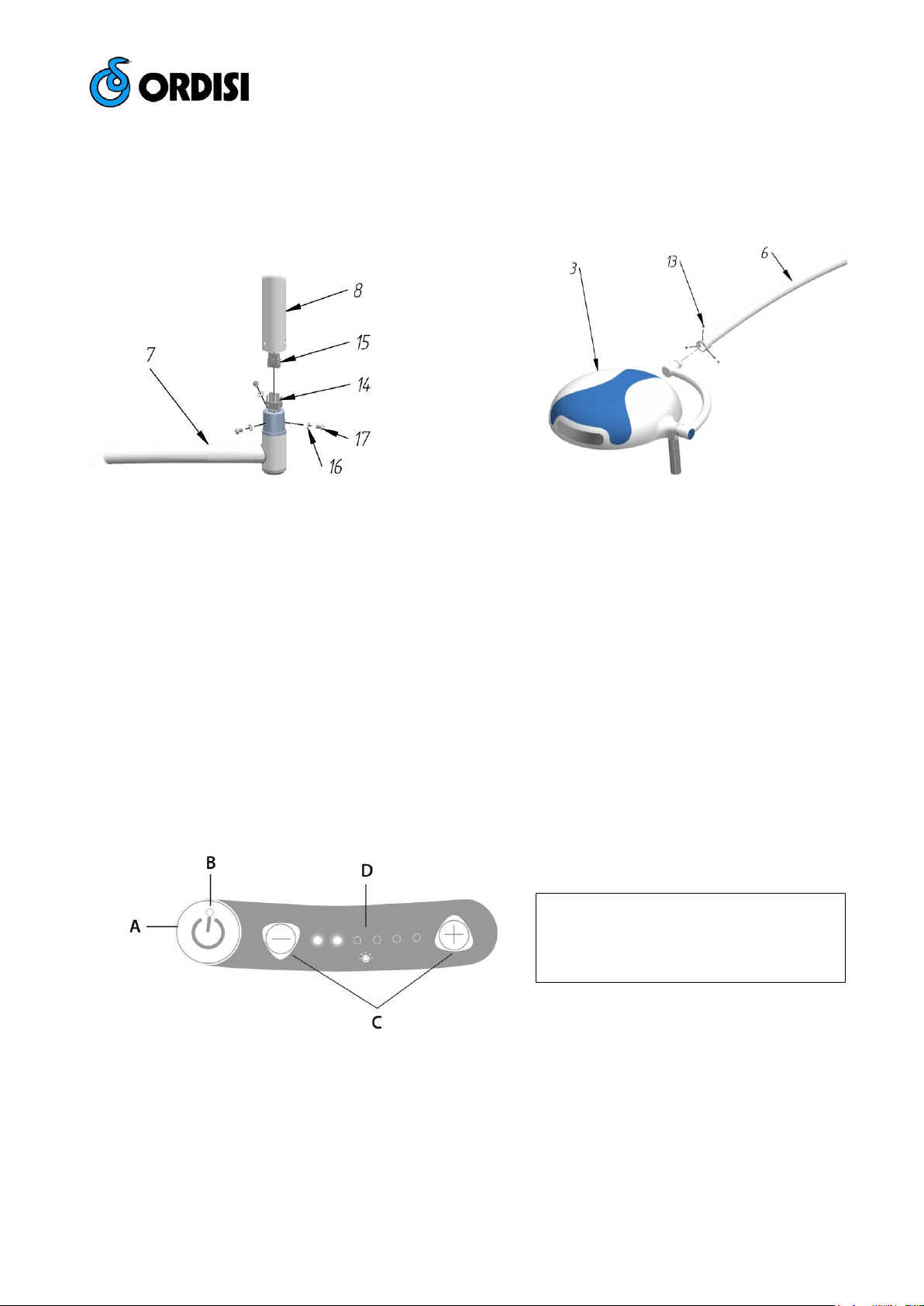
3.- DESCRIPCIÓN DE LAS PARTES
1. Mango
2. Módulo LED
3. Cúpula
4. Horquilla
5. Teclado
6. Brazo basculante
7. Brazo horizontal
8. Brazo vertical
9. Embellecedor
ESPAÑOL
Fig. 1 – Partes de la lámpara IG-65C.

Página 3 de 13
4- INSTALACIÓN
4.1.- DESEMBALADO
Si al recibir el equipo observase que el embalaje está deteriorado, comprobar que no haya sido afectado el aparato .
Si fuese así, avisar inmediatamente al remitente.
4.2. - MONTAJE
4.2.1. – MONTAJE DEL ANCLAJE
El montaje y la instalación de lámpara serie IG-65C deben tener lugar conforme a las Instrucciones de montaje del presente
manual y ser ejecutados únicamente por personal de ORDISI o por empresas de montaje autorizadas. Un mal montaje de la
misma puede tener como consecuencia que se suelte durante su funcionamiento, pudiendo producir lesiones graves tanto
en el paciente como en el personal sanitario.
El tipo de anclaje que se describe está diseñado para techos de hormigón armado ejecutados según DIN 1045. En otros
tipos de techo, la sujeción deberá ser proyectada en la obra.
La lámpara ha sido diseñada para una altura de techo de unos 275
cm, para alturas distintas adaptar el brazo vertical, ver punto 4.2.2.
Para la fijación de la placa anclaje al techo, marcar los tres taladros
ayudándose de la plantilla suministrada. Tres taladros de Ø10 y una
profundidad de 80 mm.
Una vez hechos los taladros introducir los tacos nº 10 y sujetar el
anclaje nº 11 utilizando las arandelas nº 12 y los tornillos nº 13.
Nivelar la placa.
10
11
12
13
4.2.2.- MONTAJE DE LOS BRAZOS
La lámpara está diseñada para un techo con una altura de 275
cm como máximo. La altura de la lámpara irá en función del
área de trabajo: debe quedar a una distancia aproximada de
unos 100 cm del área de trabajo. Si es necesario se podrá
ajustar la altura recortando el brazo vertical nº 8.
H brazo vertical = H techo – ( 92 + H cúpula al suelo )
medidas en cm
80
10O

Página 4 de 13
Una vez montado el anclaje ensamblar el brazo horizontal nº 7 al brazo vertical nº 8, uniendo los conectores eléctricos nº 14
y 15 y sujetar mediante las arandelas nº 16 y tornillos nº 17 suministrados (Ver Fig. 2a).
Posteriormente ensamblar la cúpula nº 3 con el brazo basculante nº 6 y apretar los tornillos nº 13. Es importante ajustarlos
dejando que la horquilla se mueva con suavidad (Ver Fig. 2b).
4.2.3.- INSTALACIÓN ELÉCTRICA
La instalación eléctrica de la sala en donde se vaya a utilizar el equipo debe ser conforme a las normas UNE (CEI 60364-
710), así como con el Reglamento de Baja Tensión. La instalación eléctrica en el local debe incluir un fusible, así como un
interruptor de red para la separación simultánea de la lámpara al grupo de abastecimiento.
Es imprescindible que la lámpara esté debidamente conectada a tierra. Conectar la red a la regleta situada en la placa
anclaje. Tensión admitida de 100-240V AC.
Una vez hechas las conexiones comprobar el buen funcionamiento del equipo y montar el embellecedor nº 9.
4.3. - PUESTA EN MARCHA
1. Poner el interruptor de la sala en ON. Debe aparecer una luz indicativa roja en el teclado.
2. Poner en marcha la lámpara por medio del teclado nº 5, y ajustar la intensidad lumínica con los botones + y -. (Ver Fig.
3)
3. Para cambiar la posición de la lámpara, hacerlo por medio del mango nº 1. Realizar los movimientos con suavidad,
evitando brusquedades.
4. La lámpara sale ajustada de fábrica. Si fuera necesario un reajuste siga los pasos del punto 6.2.
4.4.- RECOMENDACIONES DE USO
Mover la lámpara con suavidad, evitando movimientos bruscos.
Si no se está utilizando la lámpara, no la mantenga funcionando, ya que además de gastar energía inútilmente, se acorta la
vida útil del módulo LED.
Fig. 2a – Ensamblaje de los brazos.
Fig. 2b – Montaje de la horquilla
A – Botón de encendido / apagado
B – Led indicativo encendido / apagado
C – Botones regulación de intensidad lumínica
D – Leds indicativos intensidad lumínica
Fig. 3 – Teclado IG-65C

Página 5 de 13
5.- LIMPIEZA
Antes de efectuar cualquier operación, asegúrese que la lámpara está apagada.
La lámpara se debe limpiar regularmente con un paño humedecido con agua, cuidando que ésta no penetre en el interior de
la cúpula. Para las manchas persistentes; p.e. sangre, desinfectantes, etc.; se puede utilizar un poco de jabón neutro. No
utilizar bajo ningún concepto productos que contengan acetona.
Secar bien la lámpara antes de utilizarla. Si han penetrado líquidos en el interior, se deberá esperar el tiempo preciso hasta
que estos se evaporen.
El mango situado en la cúpula es esterilizable por medio de vapor de agua a una temperatura de 121ºC con un tiempo de
exposición de 20 minutos.
6.- ENTRETENIMIENTO Y MANTENIMIENTO
6.1. - VERIFICACIONES PERIÓDICAS
Periódicamente, siguiendo el Protocolo del Hospital, los Servicios de Mantenimiento deberán realizar las siguientes
verificaciones:
1) Verificar el funcionamiento general de la lámpara.
2) Verificar movilidad del brazo y la cúpula. Ver punto 6.2.
3) Comprobar la continuidad de la toma de tierra y su correcta conexión.
4) Verificar estado general (limpieza. etc.).
6.2. – AJUSTE DE LOS BRAZOS
Verificar el ajuste de las rótulas, tanto del brazo basculante como de la horquilla y la cúpula (Ver Fig. 4a).
En caso necesario proceder a su ajuste: deben moverse sin esfuerzo y mantenerse en la posición deseada. Un
exceso de apriete de los mismos puede producir un bloqueo del movimiento. Ajustar por medio de los tornillos nº
18,19, 20 o 21.
6.3. - CAMBIO DE FUSIBLES
En caso que el interruptor esté en posición "on" y la lámpara conectada a red, ésta no funcionase, compruebe el
estado del fusible siguiendo estas instrucciones:
1) Desmontar el embellecedor nº 9.
2) Desenroscar el portafusibles aéreo y reemplazar el fusible. (250VF2A). Comprobar en placa de características.
3) Montar embellecedor.
Fig. 4b – Ajuste de cúpula y horquilla.
Fig. 4a – Ajuste del brazo basculante.

Página 6 de 13
7. - CARACTERÍSTICAS TÉCNICAS
Conexión eléctrica 100-240V / 47-63Hz
Intensidad luminosa a 100cm 65.000 lux (± 10%)
Regulación de intensidad De 20.000 a 65.000 lux
Fuente de luz LED
Vida LEDS > 50.000 h
Temperatura de color 4.500K (± 5%)
CRI >95
Potencia 28 W
Ø de la cúpula 300 mm
Ø campo de trabajo d10 260 mm
Ø campo de trabajo d50 130 mm
Profundidad de campo (L1 + L2) 170 cm (80 + 90cm)
Color RAL 9002
Peso aprox. Lámpara 19.5 Kg.
MODELOS:
IG-65M Lámpara rodable
IG-65W Lámpara con soporte a pared
IG-65C Lámpara de techo
IG-65DC Lámpara de techo doble
IG-65MB Lámpara con equipo de emergencia
8. – PLANOS Y ESQUEMAS
Ver página 12
Fig. 5 – Medidas generales

Página 7 de 13
INDEX
1.- INTRODUCTION
2.- MANUFACTURER’S LIABILITIES
3.- PARTS DESCRIPTION
4.- INSTALLATION
4.1.- UNPACKING
4.2.- MOUNTING THE LAMP
4.2.1.- INSTALLATION OF THE FIXTURE
4.2.2.- ARM INSTALLATION
4.2.3.- ELECTRICAL INSTALLATION
4.3.- TURNING ON THE LAMP
4.4.- RECOMENDATIONS FOR USE
5.- CLEANING AND STERILIZIG
6.- MAINTENANCE AND UPKEEP
6.1.- PERIODIC CHECKS
6.2.- ADJUSTMENT OF THE ARM
6.3.- CHANGE THE FUSES
7.- TECHNICAL CHARACTERISTICS
8.- PLANS AND DRAWINGS
1.- INTRODUCTION
We would like to thank you for the trust you have placed in ORDISI, S.A. when you purchased a lamp from the IGLUX series.
Your lamp model IG-65C, has specially designed for a recognition, for any medical specialty, but mainly in places where a
total absence of calorific radiation is required, conserving very good quality of light.
Please read this manual carefully in order to ensure your model IG-65C gives you many years of trouble free use. If you have
any requires about your IG-65C, please contact your nearest ORDISI distributor or contact us to our head office directly:
ORDISI, S.A.
Tecnología, 2
0780 Pallejá (Barcelona) - España
Tel.: +34 93 334 01 12
Fax.: +34 93 440 25 64
e-mail: [email protected]om
2.- MANUFACTURER’S LIABILITIES
ORDISI, S.A. is responsible to whatever is related to the equipment safety, reliability and operation but only if:
The installation is strictly performed meeting the instructions of this manual.
The readjustment, extensions, alterations, and/or repairs are
performed by ORDISI, S.A. duly authorized personnel.
The electrical installation in the related premises metes I.E.C. (U.N.E.)
standards and the Low Voltage Regulations.
The equipment is operated according to this manual’s instructions.
If any accessories and consumables regularly replaced are original
accessories and consumables or are homologated and authorized by
ORDISI, S.A.
3.- PARTS DESCRIPTION
1. Handle
2. LED's module
3. Cupola
4. Yoke
5. Switch
6. Moving arm
7. Horizontal arm
8. Vertical arm
9. Embellisher
ENGLISH
Fig. 1 – Parts of the IG-65C lamp.

Página 8 de 13
4. - INSTALLATION
4.1. - UNPACKING
Upon reception of the equipment, if package is seen as damaged, immediately check if device has been affected.
When device is checked and damages are confirmed, immediately refer then to the technical service for a review
and be sure that not any internal failure has happened.
4.2. - MOUNTING
4.2.1.- INSTALLATION OF THE MOUNTING PLATE
The assembly and installation of lamp IG-65C must take place under the mounting instructions in this manual and be
undertaken only by personnel of ORDISI or authorized assemblers. A bad installation may have the effect of loose during
operation, and this can cause serious injury to the patient and health personnel.
The type of the fixture described in this manual is designed for concrete rooftops executed according to DIN 1045. In other
types of roof, the fixation must be projected in the building
work.
The lamp has been designed for a ceiling height of 275 cm, for
different heights adjust the vertical arm nº 8. See section 4.2.2.
For fixing the mounting plate to the ceiling, use the provided
template to mark the three holes. It must be three holes Ø10
mm and a depth of 80 mm.
Once the holes are made, introduce the plug nº 10 and attach
the mounting plate nº 11 using washers nº 12 and screws nº
13. Level the plate.
10
11
12
13
4.2.2. - ARM INSTALLATION
The lamp is designed for a ceiling with a height of about 275 cm
high. The height of the lamp will depend on the work area: it should
remain at a distance of approximately 100 cm from its workspace.
If necessary, you can adjust the heigth cutting the vertical arm nº 8.
H vertical arm = H ceiling – ( 92 + H head light to floor )
Measurements in cm
80
10O

Página 9 de 13
Once mounted the ceiling plate, assemble the horizontal arm nº 7 to vertical arm nº 8, join the electrical connectors nº 14 and
nº 15 and fix by washers nº 16 and screws nº 17 (See Fig. 2a).
After that, assemble the cupola nº 3 with the arm nº 6. Hold the copula through the screws nº 13, and adjust it until you can
move the copula with a gentle moving (See Fig. 2b).
4.2.3. - ELECTRICAL INSTALLATION
Electrical installation of the room where you plan to use the equipment should be in accordance with the rules UNE
(CEI60364-710), as well as the Low Voltage Regulation. Electrical installation of the room must include a fuse and a
switch network for the simultaneous separation of the lamp with electric supply.
It is essential that the lamp is properly grounded. Connect the network to the terminal located in the ceiling plate.
Supported Voltage is 100-240V AC.
Once you make the connections, check the proper operation of equipment and mount the embellisher nº 9.
4.3. - TURNING ON THE LAMP
1. Turn on the switch of the room. A red light should appear in the keypad when the lamp is connected.
2. Turn on the lamp, using the keypad No.5, and adjust the light intensity with the + and – buttons. (See Fig. 3)
3. To change the position of the lamp, use the handle nº 1. Do that gently, avoiding brusque movements.
4. The lamp is adjusted at factory. If necessary a readjustment, see point 6.2.
4.4.- RECOMENDATIONS FOR USE
Move the lamp gently, avoiding brusque movements.
If the lamp is not in use do not leave it on, since apart from wasting electricity you will reduce the useful life of the LED.
Fig. 2a – Assembly of the arms.
Fig. 2b – Fork and cupola assembly
A – On / Off button
B – On / Off Led indicator
C – Luminous intensity adjustment buttons
D – Luminous intensity Leds indicators
Fig. 3 – Keypad

Página 10 de 13
5. CLEANING
Before doing anything, make sure the lamp is off.
The lamp must be cleaned regularly with a cloth dampened with water, taking care that water does not reach the inside of the
equipment via the ventilation grille. For persistent stains such as blood, disinfectants, etc… a little neutral soap can be used.
Do not use products containing acetone in any case.
Dry the lamp well before use. If there is liquid inside you must wait until it has evaporated.
The handle located on the cupola is sterilizable by steam media at a temperature of 121°C with an exposure time of 20
minutes.
6. - MAINTENANCE AND UPKEEP
6.1. - PERIODIC CHECKS
According to hospital procedures, the maintenance service should periodically carry out the following checks:
1. Check the general working order of the lamp.
2. Check the mobility of the arm and cupola. See point 6.2.
3. Check the equipment is still earthed and is correctly connected.
4. Check its general state (of cleanliness, etc…).
6.2. – ADJUST OF THE ARM
Check the adjustment of the round joints, both of the rocker arm and the fork and the dome too. If necessary,
proceed to adjust them: it must move effortlessly and stay in position. An excessive tightening of them may produce
a blockage of the movement. Adjust by screws nº 18, 19 , 20 or 21.
6.3. - CHANGE THE FUSES
If the switch is "on" and the lamp is connected to the network, and it did not work, check the fuse following these
instructions:
1. Remove the embellisher nº 9.
2. Unscrew the fuse box using a screwdriver and replace the fuse. (250VF2A). Check on ceiling plate.
3. Install the embellisher.
Fig. 4b – Cupola and fork adjustment.
Fig. 4a – Arm adjustment.

Página 11 de 13
7. - TECHNICAL CHARACTERISTICS
Electrical connection 100-240V / 47-63Hz
Luminous intensity at 100 cm 65.000 lux (± 10%)
Illumination intensity adjustment from 20.000 to 65.000 lux
Light source LED
Colour temperature 4.500 K (±5%)
Led Power 28 W
Ø Screen diameter 300 mm
Field diameter d10 260 cm
Field diameter d50 130 cm
Depth of field (L1 + L2) 170 cm (80 + 90cm)
Colour RAL 9002
Approximate lamp Weight 19.5 Kg
MODELS:
IG-65M Moveable lamp
IG-65W Wall mount lamp
IG-65C Ceiling lamp
IG-65DC Ceiling lamp with double arm
IG-65MB Moveable lamp with battery equipment
8. - PLANS AND DRAWINGS
See page 12
Fig. 5 – General dimensions

Página 12 de 13
8. – PLANOS Y ESQUEMAS / PLANS AND DRAWINGS
Fig. 6 – Despiece de la cúpula / Exploded view of the cupola

Página 13 de 13
Fig. 7 – Despiece de brazos y anclaje a techo / Exploded view of the arms and ceiling mount.
Table of contents
Languages:
Other ORDISI Medical Equipment manuals
Popular Medical Equipment manuals by other brands

GERATHERM
GERATHERM UniqueResc+ instruction manual

Boston Scientific
Boston Scientific EASYTRAK 2 IS-1 Physician's lead manual

Gima
Gima PC-900 manual

Otto Bock
Otto Bock 7E9 Instructions for use

Stryker
Stryker Secure 3000 Maintenance manual

Ivoclar Vivadent
Ivoclar Vivadent Bluephase Style 20i Instructions for use