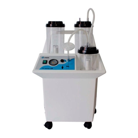
ORDISI ASPIT User manual

Manual de utilizare
Și întreținere
Maintenance and
Functioning manual
Mom-09
Edición 12
Fecha edición 2019/11/04
Tecnologia 2 –Nave 7
08780 Palleja
Barcelona - Spain
(34) 93 334 01 12
FAX (34) 93 440 25 64
comercial@ordisi.com
www.ordisi.com

Pág. 2 de 9
TABLE OF CONTENTS
1.-INTRODUCTION
2.-MANUFACTURER’S LIABILITIES
3.-PARTS DESCRIPTION
4.-INSTALLATION AND COMMISSIONING
5.-CLEANING AND STERILIZING
6.-ENTERTAIMENT AND MAINTENANCE
7.-TECHNICAL CHARACTERISTICS
8.-SPECIAL ACCESSORIES
9.-DIAGRAMS AND DRAWINGS
10.- POSSIBLES AVERAGES AND THEIR CORRECTION
11.- TECHNICAL SPECIFICATION, EMC INFORMATION
1.- INTRODUCTION
Your straightforward assurance on our products by purchasing an ORDISI, S.A. portable aspirator of the ASPIT
series, is very much appreciated.
Before to start the aspirator we recommend you to read carefully this manual. If you have any doubt, please contact
with your provider, or directly with ORDISI, S.A.
ORDISI, S.A.
Tecnologia, 2
08780 Palleja (Barcelona) -España
Tel.: +34 93 334 01 12
Fax.: +34 93 440 25 64
2.- MANUFACTURER’S LIABILITIES
O
OR
RD
DI
IS
SI
I,
,
S
S.
.A
A
. is responsible to whatever is related to the equipment safety, reliability and operation but only:
•If equipment is operated according to this manual’s instructions.
•If any accessories and consumables regularly replaced, are original and/or confirmed by ORDISI, S.A.
•If readjustment, extensions and/or repairs, are performed by ORDISI, S.A.’s duly authorized personnel.
3.- PARTS DESCRIPTION
1.- ON/OFF light-switch
2.- Vacuum gauge
3.- Patient’s connector
4.- Vacuum connector
5.- Top
6.- Safety valve
7.- Collection bottle
8.- Vacuum regulator
9.- Power supply cable
10.- Fuses and fuse holder
11.- Characteristics plate
12.- Bacteria filter
13.- Body
ENGLISH

Pág. 3 de 9
4.- INSTALLATION AND COMMISSIONING
4.1.- UNPACKING
Upon reception of the equipment, if package is seen as damaged, immediately check if device has been affected. If
damages are confirmed, immediately refer them to sender.
4.2.- COMMISIONING
Not to use in explosive atmospheres like the anesthetic produced ones by inflammable.
1) Check room electrical installation where equipment is tobe fitted it such installation meets IEC (UNE) standards
with a good earthing. Check voltage is same as show in the nameplate
2) Press ON/OFF light-switch Nº 1. Light-switch should now be lighted and device start its operation.
3) With the aspirator, you will find a aspiration set for a single use, (GRAVE RISK OF INFECTION IF USED IN
MANY PATIENTS) composed by 2 meters of suction tube, one probe, and connector. The union of the probe
and the suction tube, is through the grooving connector, by pressure. Connect the other extreme of the tube, in
the connector patient, as shown in the plug of the bottle Nº 3, and turn on the aspirator. To see point 2 section
4.3.
References for new orders
US0110020 3 meters suction tube (20 units)
US0214100 aspiration probe CH14 (100 units)
US1000020 conical connector (20 units)
FB-194A Bacterial filter
4) Through vacuum regulator control Nº 8, is possible to increase or to decrease vacuum level.
5) Vacuum gauge Nº 2 will show, at any time, the vacuum level being actually caused on the
patient.(tolerance±1.6%). It is recommended that in normal conditions, the calibration of the vacuum-gauge is
made once every two years.
4.3.- RECOMENDATIONS FOR USE
1) Avoid an excessive filling of the collection bottle (recommended not to fill more that 80% of his capacity),
a possible overflowing and penetration of liquid in the pump interior will thus be prevented. In this case, we
advise you to remove the pump lathe head for to clean it, by an Authorized Technical Service.
2) Excessively large suction tubes should never be used, because they have a trend to nipping and any
subsequent collapse will cause a suction choking. On the other hand, a risk is run that elbows are made up
wherein aspirated fluids can be settled originating therefore a possible infection and pollution centre.
Periodically replace the tube of aspiration by a specific tube for this one assignment (it must take to noticeable
CE of conformity fulfilling the norm UNE EN 1617 of drainage tubes). Verify when replacing these and before
coming to the
We recommended the use of the following tubes of aspiration:
-PVC tube minimum inner diameter 6 mm by 9 mm of outer diameter.
-Silicone tube minimum inner diameter 6 mm by 10 mm of outer diameter.
3) Avoid patient resting on the suction tubes in a way that suction might be choked.
4) Clean and sterilize the top Nº 5, the safety valve Nº 6 and the bottle, after of each use.
5) Never run the aspirator if a vacuum is detected in the circuit, previously have vacuum level decreased to 0.
6) This equipment have not been designed for continuous drainage. Do not use it for this purpose.
7) Is advisable to use an antifoaming for to avoid that the accumulation of foaming in the bottle, covers the filling
level.
8) Never connect any mechanism nor arrangement (as ventilators, aerosol generators, etc.) to the air outlet.
9) In case of excessive filling of bottle and if take the safety valve Nº 6, the aspirator don’t work. To stop the
equipment with the switch, decreased the vacuum level to 0 with the vacuum regulator Nº 8 and to change or to
empty the bottle.
10) The biological risk waste will be removed following the protocol of the hospital waste management

Pág. 4 de 9
4.4.- RELATIVES DIRECTIONS FOR TO USE THE ASPIRATOR
Portable aspirator of high capacity of work and strength that for his power and flow, is indicated for:
•Minor surgery.
•Remove body fluids.
•Removing mucus.
This equipment is not appropriate to work in operating rooms where it suspects that can have inflammable
atmosphere risk.
The contraindications and/or precautions, and possible adverse effects, according to clinical evaluation are the
followings:
•Critical elements to consider by a surgeon: the quantity of fluid that will have to be extracted and precautions
to take for getting that this extraction isn’t traumatic.
•As a normal associated effects with the aspiration are described in the followings: passenger edema, pain,
smaller scars and drilling intraperitoneal / intrathoracic.
•For a bibliography review, the described complications are: infection, haematomas, blood loss.
ASPIT-G model has the same indications. The variation is that the inlet diameter of the plug is higher (8.5 mm)
5.- CLEANING AND STERILIZING
5.1.- BODY
Before undertaking any operation, disconnect the equipment from electricity supply.
Use personal protective equipment as directed by the unit of occupational hazards and preventive medicine.
The outer casing of the equipment can be washed using a mild detergent and a damp cloth.
Disinfect is necessary using a disinfectant.
The probes and suction tubes are single use must not be reused.
5.2.- COLLECTING BOTTLE
The collecting bottle Nº 7, and the top with the valve (Nº 5 and Nº 6) are supplies without to sterilize. You must to
sterilize its before the first operation.
DON’T USE BLEACH OR SIMILARS
To proceed to washing and disinfection / sterilization of the bottle, cap, valve and valve holder can be used:
• Washing: Always perform this operation using a neutral detergent and eliminating all biological fluids
• High Level Disinfection: Disinfect after each use with a disinfectant.
• if it is necessary Sterilize by steam (validated cycle of 121°C at 1atm pressure for 30 minutes).

Pág. 5 de 9
6.- ENTERTAIMENT AND MAINTENANCE
6.1.- BACTERIA FILTER CHANGE
The bacterial filter included in your equipment is a closed system filter, It is NON REUSABLE, (GRAVE RISK OF
INFECTION IF USED IN MANY PATIENTS).
NEVER USE YOUR ASPIRATOR WITHOUT BACTERIA FILTER
6.2.- FUSES CHANGE
If device is connected to the power supply and switch Nº 1 is at position “1”, there is not any operation and the switch
is not lighted, check then the fuses condition following up these instructions:
1) Remove plugs of fuseholders Nº 10 with a screw-driver.
2) If damaged, replace fuses with news ones (Ref. RC009954)
3) Replace plugs at original position.
7.- TECHNICAL CHARACTERISTICS USING SYMBOLS
•High vacuum aspirator.
•Low flow aspirator.
•Pump of double membrane.
•Pump flow: 800 l/h.
•Max. vacuum: 84 Kpa (630 mmHg).
•Glass bottle capacity: 1’6 litres.
•Measurements: 340x150x300
•Weight: 4,600 Kg.
•Power: 105 VA
•Voltage: 230V / 50 Hz
•Fuses: 2 of 2A, type F.
•(Consult us for other voltage).
•Equipment of I Class B type.
•Average life: 10 years
8.- SPECIAL ACCESSORIES
•ON/OFF pedal , with electrical microswitch , and 3,5 meters of electrical cable; Ref. A017078.
•Hydrophobic bacteria filter; Ref. FB-193, bag 10 units.
9.- DIAGRAMS AND DRAWINGS
At the request of the customer, ORDISI, S.A. will be supply components lists, description of its, calibration
instructions and whatever necessary information for to repair the equipment by qualified technical personnel.
In the present manual, we herewith enclose the electrical diagram and one complete exploded view of the equipment.
9.1.- PNEUMATIC DIAGRAM
1.- Patient.
2.- Collecting bottle.
3.- Safety valve
4.- Bacteria filter
5.- Vacuum regulator
6.- Vacuum gauge
7.- Motor-pump
8.- Air outlet
Consult accompaniment documents.
Protection earth (inside).
Equipment of B class.
Year of manufacture
CE registered for notified organization
Selective collection of electrical apparatuses

Pág. 6 de 9
9.2 DIAGRAM ELECTRIC
9.3.- EXPLODED VIEW
See page 12 & 13
10.- TROUBLESHOOTING
FAILURE OR MALFUNCTION
CAUSE
SOLUTION
Equipment starts up but doesn’t
aspirate.
Regulation control is open.
Close control.
Suction tube wrongly inserted..
Insert correctly.
Cap improperly adjusted.
Adjust properly.
Equipment starts up but suction is not
enough or inexistent.
Bacterial filter is saturated.
Change filter.
Failure continues.
Entry of liquid inside the pump.
Disassembly and cleaning of pump
head by Technical Services.
Equipment doesn’t start up nor the
luminous switch lights up.
Examine the fuse possible deterioration and
the power plug.
Replace the fuse or the plug.
Failure continues.
?
Contact Technical Services.
11.- TECHNICAL SPECIFICATION, EMC INFORMATION
Guidance and manufacturer’s declaration – electromagnetic emissions
The system is intended for use in the electromagnetic environment specified below.
The customer or the user of the equipment should assure that it is used in such an environment.
Emissions test
Compliance
Electromagnetic environment –guidance
RF emissions CISPR 11
Group 1
The equipment uses RF energy only for its internal function. Therefore,
its RF emissions are very low and are not likely to cause any
interference in nearby electronic equipment.
RF emissions CISPR 11
Class B
The equipment is suitable for use in all establishments, including
domestic establishments (not industrially) and those directly connected
to the public low-voltage power supply network that supplies buildings
used for domestic purposes.
Harmonic emissions IEC61000-3-2
Class A
Voltage fluctuations/ flicker
emissions IEC61000-3-3
Complies
Guidance and manufacturer’s declaration – electromagnetic immunity
The equipment is intended for use in the electromagnetic environment specified below.
The customer or the user of the equipment should assure that it is used in such an environment.
IMMUNITY test
IEC 60601
test level
Compliance level
Electromagnetic environment
guidance
Electrostatic
discharge (ESD)
IEC61000-4-2
±6kV contact
±8kV air
±6kV contact
±8kV air
Floors should be wood, concrete or
ceramic tile. If floors are covered with
synthetic material, the relative humidity
should be at least 30 %.
Electrical fast
transient/burst
IEC 61000-4-4
±2kV for power supply lines
±1KV for input/output lines
±2kV for power supply
lines
Mains power quality should be that of a
typical commercial or hospital
environment.
Surge
IEC 61000-4-5
±1kV line(s) to line(s)
±2kV line(s) to earth
±1kV line(s) to line(s)
±2kV line(s) to earth
Mains power quality should be that of a
typical commercial or hospital
environment.

Pág. 7 de 9
Voltage dips, short
interruptions and
voltage variations
on power supply
input lines
IEC 61000-4-11
<5%UT (>95% dip in UT) for
0,5 cycle
<40%UT (>60% dip in UT)
for 5 cycles
<70%UT (>30% dip in UT)
for 25 cycles
<5%UT (>95% cycles UT)
for 5 s
Ídem
Mains power quality should be that of a
typical commercial or hospital
environment. If the user of the
equipment requires continued operation
during power mains interruptions, it is
recommended that the equipment be
powered from an uninterruptible power
supply or a battery.
Power frequency (50/60 Hz)
magnetic field IEC 61000-4-
8
3 A/m
3 A/m
The power frequency magnetic field
should be measured in the intended
installation location to assure
VACCUM VARIATION IN RELATION TO ALTITUDE
ABOVE SEA LEVEL, AT A TEMPERATURE OF 22ºC
Altitude above sea
level
ASPIT Model
Ph (mmhg)
Ph (kPa)
0 m
630
80
500 m
566
75,5
1000 m
534
71,2
1500 m
504
67,2
2000 m
476
63,4
2500 m
449
59,8
3000 m
424
56,5

Pág. 8 de 9
ASPIT

Pág. 9 de 9
ASPIT-G
This manual suits for next models
1
Table of contents
Other ORDISI Medical Equipment manuals
Popular Medical Equipment manuals by other brands

Bionet
Bionet Cardio P1 Service manual

ARJO HUNTLEIGH
ARJO HUNTLEIGH NIMBUS 4 Quick reference guide

Hillrom
Hillrom Centuris Pro Instructions for use

ARJO HUNTLEIGH
ARJO HUNTLEIGH Flowtron ACS900 Instructions for use

ARJO HUNTLEIGH
ARJO HUNTLEIGH FLOWTRON UNIVERSAL Instructions for use

Hillrom
Hillrom O-ABSLT Instructions for use