Embla S4500 Instructions for use

Embla®S4500™
Clinical Manual

Embla S4500 Clinical Manual
Copyright © 2008 Embla. All rights reserved.
Issued May 2008
Document #: D-0709-053, Revision 1.0 JLB
Document Item #: 2800107
Embla
11001 W. 120th Ave.
Suite 200
Broomfield, CO 80021
USA
Tel: +1.303.962.1800
Toll-Free: 888.662.7632
Fax: +1.303.962.1810
Kon. Wilhelminaplein 13/2.09.05
1060 CM Amsterdam
P.O. Box 69464
The Netherlands
Tel: +31 20 3460130
Fax: +31 20 3460121
Website:
www.embla.com
Email:
Copyright Notice
No part of this publication may be reproduced, transmitted, transcribed, stored in a retrieval
system, or translated into any language or computer language, in any form, or by any means,
electronic, mechanical, optical, chemical, manual, or otherwise, without the prior written consent
of Embla.
Disclaimer
This document may contain technical inaccuracies or typographical errors. Changes are
periodically made to the information herein; these changes will be incorporated in future
revisions of this document. Embla does not accept any liability for the use or misuse, direct or
indirect, of this product. Users must accept all responsibility for any results obtained by or
concluded from data obtained by the products. The user must accept all responsibility for
results obtained by software from Embla. All clinical conclusions and decisions that are made
based on the use of this product are the responsibility of the user. Embla does not accept any
liability or responsibility for damages arising out of the use of or inability to use this product.
Trademarks
S4500, RemLogic, Somnologica and XactTrace are trademarks of Embla Systems Inc.
REMbrandt and Embla are registered trademarks of Embla Systems Inc. All other trademarks
are the property of their respective owners.
The Embla S4500 is manufactured by Cogent Technologies in the United Kingdom for Embla
Systems Inc.
Printed in the Netherlands.


i
Contents
About This Manual.........................................................................................1
About the Embla S4500 System.................................................................2
Safety and Regulatory Information...................................................................................................... 2
Warnings, Cautions and Contraindications ............................................3
Warnings and Cautions........................................................................................................................... 3
Intended Use ............................................................................................................................................. 5
Certifications.............................................................................................................................................. 5
Classifications............................................................................................................................................ 6
System Components ......................................................................................7
Communication Unit.................................................................................................................................. 7
About the Communication Unit ........................................................................................................... 7
Rear Panel.............................................................................................................................................. 8
Communication Unit Cables ..............................................................................................................10
Bedside Unit ............................................................................................................................................10
Status Lights.........................................................................................................................................11
Impedance Test Button .......................................................................................................................12
Channel Inputs.....................................................................................................................................12
Cable ....................................................................................................................................................14
Mounting Bracket................................................................................................................................14
Shoulder Strap ....................................................................................................................................15
Sensors......................................................................................................................................................15
Electrodes.............................................................................................................................................15
Sensor Inputs .......................................................................................................................................16
Assembling the System.............................................................................. 18
Mounting the Bedside Unit Bracket.....................................................................................................18
Mounting the Communication Unit .......................................................................................................19
Creating and Attaching an ID Card to the Communication Unit...................................................20
Connecting the Units...............................................................................................................................21
Connecting the Communication Unit ................................................................................................21
Connecting the Bedside Unit..............................................................................................................22
Installing the System on the Network...............................................................................................24
Connection Types ................................................................................................................................25
Performing a Study ..................................................................................... 27
Study Types.............................................................................................................................................27

Embla S4500 Clinical Manual
ii
Attaching the Electrodes........................................................................................................................27
Attaching the Oximeter and Oximeter Flex Sensor........................................................................30
The Oximeter Sensor..........................................................................................................................31
Attaching the Oximeter Flex Sensor................................................................................................31
Other Oximeter Sensors....................................................................................................................33
Attaching XactTrace Respiratory Effort Sensors ..............................................................................34
Fitting the XactTrace Belt...................................................................................................................34
Attaching the XactTrace Belts to the Patient...................................................................................36
Storing the Belt Lock ..........................................................................................................................37
Considerations for Use.......................................................................................................................37
Attaching the Nasal Pressure Sensor..................................................................................................40
Attaching the Snoring Sensor ...............................................................................................................42
Attaching the Thermistor........................................................................................................................43
Attaching the Body Position Sensor.....................................................................................................44
Connecting Sensors to the Bedside Unit.............................................................................................45
Testing the Electrode Impedance ........................................................................................................46
Activating the Calibration Test Signal................................................................................................48
During Use................................................................................................................................................48
System Maintenance .................................................................................. 49
Cleaning the System Units.....................................................................................................................49
Cleaning Sensors ....................................................................................................................................49
Single Use Sensors..............................................................................................................................50
Environment..............................................................................................................................................50
Factory Calibration................................................................................................................................51
Disposal....................................................................................................................................................51
Troubleshooting............................................................................................ 52
Problems Starting a Recording............................................................................................................52
Unclear Signals .......................................................................................................................................52
Technical Specifications ............................................................................ 54
Communication Unit................................................................................................................................54
Bedside Unit ............................................................................................................................................55
Bedside Unit Bracket..............................................................................................................................57
Oximeter Accuracy for Type Nonin Xpod.........................................................................................58
Materials List ...........................................................................................................................................59
Further Readings.......................................................................................... 60
List of Tables ................................................................................................. 62
Glossary .......................................................................................................... 63

Contents
iii
Index................................................................................................................ 65


1
About This Manual
This clinical manual is intended for all users of the Embla S4500 system. It is assumed that users
have a basic knowledge of the Windows environment, working with a mouse, using toolbars,
and arranging windows. Sections typically begin with an overview and description of main
features, followed by instructions in simple action steps.
Embla's Knowledge Base contains helpful articles, product information, and information on the
study of sleep. Access this resource at www.embla.com/support/knowbase.
For more information on any Embla product feature, or for technical support, please contact

2
About the Embla S4500 System
The Embla S4500 system is a full polysomnography (PSG) system used to perform online sleep
studies in the sleep lab, hospital or clinical environment, under the supervision of a clinician or
sleep technician.
The Embla S4500 system integrates advanced digital technology and precision engineering
into a flexible, rugged, full polysomnography network. Featuring an Ethernet network
connection, the system is simple to assemble, with cables streamlined for comfort and reliability.
Building on the proven convenience and quality of the Embla S4000 System, the S4500 system
has 13 referential channels, 5 bipolar channels, an extensive set of respiratory data channels
as well as auxiliary inputs and digital serial ports for additional devices such as CPAP and
CO2 machines.
The Embla S4500 system can be used with Rembrandt and RemLogic.
Safety and Regulatory Information
Before using the Embla S4500 system, please read this clinical manual carefully, paying
particular attention to the caution or warning that appears with each safety symbol.
Caution:
The CAUTION notice denotes a potential hazard. It calls attention to an operating
procedure, practice, or the like, which, if not correctly performed or adhered to,
could result in damage to the product or loss of important data. Do not proceed
beyond a CAUTION notice until the indicated conditions are fully understood and
met.
Warning:
The WARNING notice denotes a hazard. It calls attention to a procedure, practice,
or the like, that, if not correctly performed or adhered to, could result in personal
injury. Do not proceed beyond a WARNING notice until the indicated conditions are
fully understood and met.

3
Warnings, Cautions and
Contraindications
Warnings and Cautions
The following warnings and cautions are applicable to the Embla S4500:
•The Embla S4500 is NOT TO BE USED FOR CONTINUOUS MONITORING where
failure to operate can cause injuries or death of the patient.
•The system must not be used for direct cardiac application.
•Caution: U.S. Federal law restricts this system to sale by, or on the order of, a
physician.
•No user serviceable parts inside. Serviced by Embla and authorized parties only.
Warranty void if opened.
•The contact of liquids with the internal parts and connectors of the Embla should be
avoided at all times. The system is neither water resistant, drip-proof nor splash-
proof and the cleaning instructions in this manual need to be strictly adhered to.
•Do not use the Embla S4500 system in an MRI environment.
•Do not use the Embla S4500 device in an explosive environment, that is, in the
presence of flammable liquids or gases.
•The system is not defibrillator proof.
•Caution must be taken to ensure that cables do not encircle the patient's neck.
Special attention is needed in the case of children.
•The Embla S4500 system does not increase the safety risk for pacemaker patients
as long as the pacemakers comply with the EN50061 standard of electrical safety
of medical devices. Nevertheless, it is not advisable to do an impedance test on
pacemaker patients since it might cause the pacemaker to switch to the interference
mode. Prior to using the system with pacemaker patients, the operator should
consult the pacemaker’s accompanying documents regarding its certifications and
requirements of use or, if necessary, contact the producer.

Embla S4500 Clinical Manual
4
•Use only with sensors and electrodes provided by Embla or with sensors that have
been validated by Embla. Use of other sensors with this device may impair the
signal quality and device performance. Contact Embla Technical Support
be used with the device.
•The Embla S4500 complies with the international standard IEC60601-1-2 for
electromagnetic compatibility for medical electrical equipment. This standard is
designed to provide reasonable protection against harmful interference in a
typical medical installation. However, because of the proliferation of radio-
frequency transmitting equipment and other sources of electrical noise in healthcare
and other environments, it is possible that high levels of interference due to close
proximity or strength of source might disrupt the device’s performance. For these
reasons, special precaution regarding EMC is needed when the device is installed
and put into service.
•Portable and mobile RF communications can affect the performance of the Embla
S4500 system.
•The Embla S4500 system should not be used adjacent to, or stacked with, other
equipment. If adjacent or stacked use is necessary, the device should be observed
to verify normal operation in the configuration in which it will be used.
•Electrostatic discharges (ESD) may cause artifacts in the signal from the device.
Avoid conditions where electrostatic charge can build up because of low humidity
and friction against carpets, clothing and sheets made from artificial fibers
•The operator must be trained to be able to recognize the difference between a
valid bio-signal and signal artifacts caused by subject movements, RF disturbances
or misplacement of sensors or electrodes.
•Before starting data acquisition with the system, always check the device profile
and patient information in the Embla PSG software application.
•Always inspect the equipment, particularly the cables and connectors, for evidence
of wear before each study. If evidence of wear is found, remove the worn
replacement or servicing.

Warnings, Cautions and Contraindications
5
Intended Use
The Embla S4500 system is intended for use by a physician or trained technician for the
acquisition of Electroencephalogram (EEG) and polysomnography (PSG) signals and their
transmission to a PC during neurophysiologic or sleep examinations. The intended environments
are hospitals, institutions, sleep centers, sleep clinics, or other test environments.
The use of the Embla S4500 system does not involve any patient monitoring or diagnosis.
Certifications
The following certifications are applicable to the Embla S4500:
0413
The Embla S4500 is certified to carry the CE mark. The CE mark is
a declaration that Embla is in compliance with the directive set forth
by the European Union for medical devices.
The ETL mark is a safety symbol which shows that the product has
been independently tested and certified to applicable U.S. and
Canadian product safety standards.
The C-Tick mark indicates that the product complies with the
applicable EMC standard and establishes a traceable link between
the product and the supplier responsible for placing it on the
Australian market.
The Embla Quality Management System complies with EN ISO
9001:2000 and EN ISO 13485:2003.
Embla certifies that the development, manufacture, sales, and
service of the Embla is in conformity with Annex II of the Directive
93/42/EEC on medical devices.
Embla S4500 Clinical Manual
6
Classifications
The following classifications are applicable to the Embla S4500:
The Embla S4500 is classified as Class II device.
Electric shock: According to the degree of protection against electric shock the
Embla is classified as of type BF.
Ingress of liquids: The Embla S4500 is classified as an ordinary equipment
regarding ingress of liquids, that is, it is not drip-proof, splash-proof or
watertight.
Degree of Safety: The Embla 4500 is not suitable for use in presence of a
FLAMMABLE ANAESTHETIC MIXTURE WITH AIR or WITH OXYGEN or NITROUS
OXIDE.
Mode of operation: Continuous.
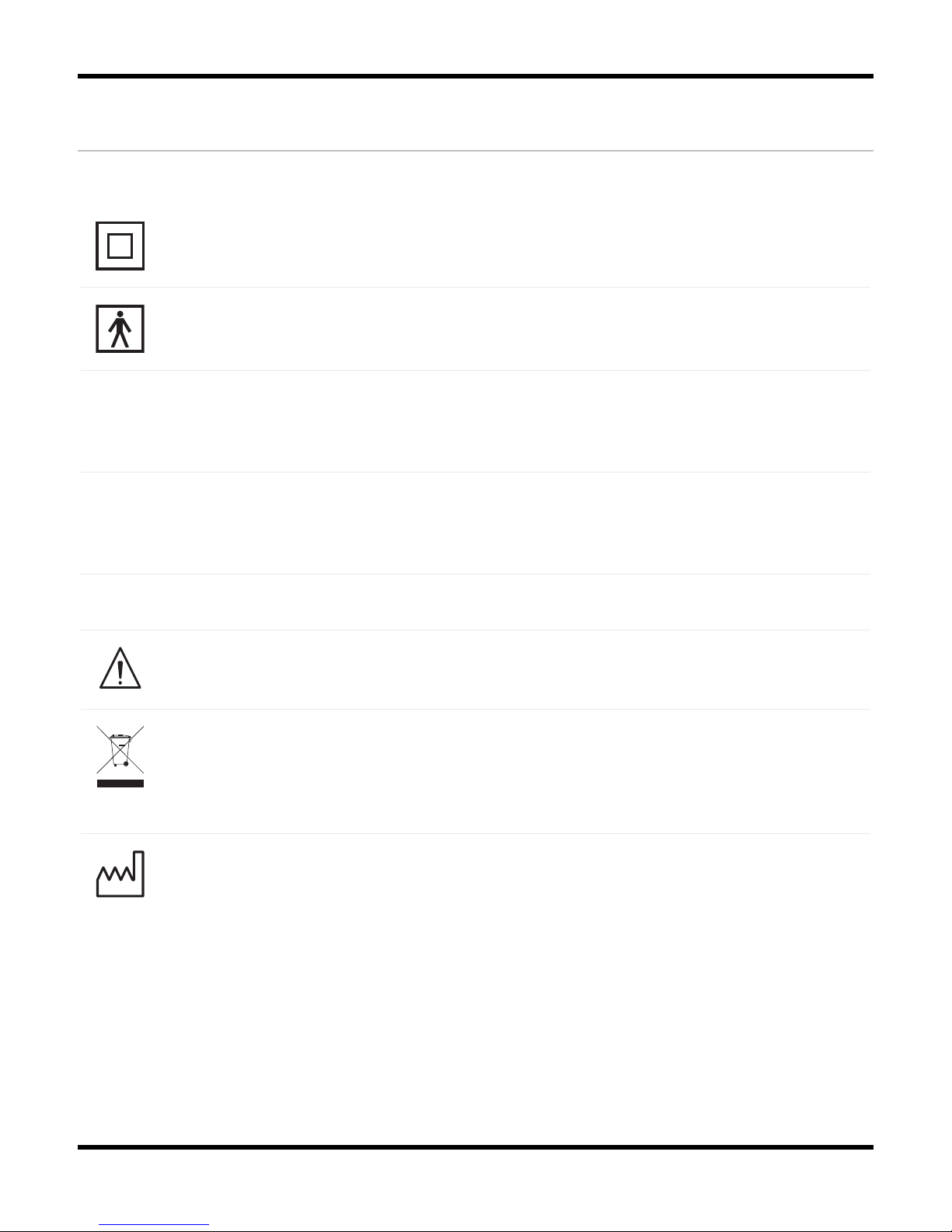
Where you see this symbol on any device label, it means "Attention: consult
accompanying documentation".
According to the regulation in Europe on Waste of Electrical and Electronic
Equipment (WEEE) the WEEE may not be disposed of as unsorted municipal waste.
The Embla S4500 should be returned to Embla when it is ready to be disposed of.
Contact Embla at support@embla.com for more information.
Where you see this symbol on the device, it means that the date of manufacture is
indicated adjacent to this symbol.
7
System Components
The Embla S4500 system is composed of two subunits that are connected together: the
Communication Unit and the Bedside Unit (also known as the Physiological Unit). The enclosure
of the Bedside Unit is connected to a bracket that holds the unit in place. The systems are
connected to a remote standard commercial personal computer through Ethernet/LAN. The
recording data is stored on the personal computer where viewing, reviewing and analysis of
the data can be done in the application software used.
Communication Unit
About the Communication Unit
The Communication Unit supplies the power to the Bedside Unit and communicates between the
Embla S4500 and an acquisition computer over a Local Area Network (LAN). It has additional
inputs for external devices such as a CPAP, and functions in part as a patient isolation unit,
preventing a direct electrical connection between the patient and the external devices
connected to the system.
Communication Unit (front view)
Four plastic fasteners are supplied with the system that can be used to secure the
Communication Unit to a wall. See Mounting the Communication Unit for more information.
The unit front panel features a power indicator light (labeled " ") which is green when the
unit is turned on.
Embla S4500 Clinical Manual
8
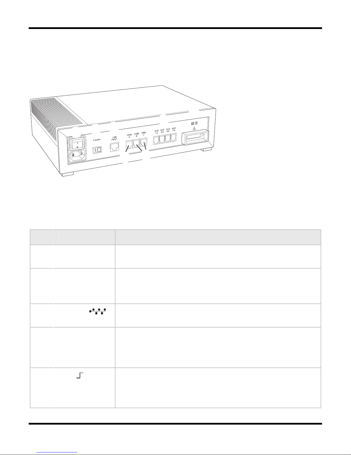
Rear Panel
The following figure shows the location of the rear panel components on the Embla S4500
Communication Unit:
BCDGH
EF
Communication Unit (rear view)
Table 1 lists and describes the Communication Unit rear panel components and symbols.
Table 1: Communication Unit Rear Panel Components and Symbols
Item Description
1 Mains power
supply
Includes an on/off switch and a mains power input.
2 Voltage
selector switch
(115/230V~)
Determines the voltage used.
3 LAN Port Communication port to the LAN. The required network
connection is twisted-pair (TP) Ethernet.
4 COM A & COM
B
Serial ports intended for use with supported devices with
digital outputs, such as a CPAP or CO2 devices. Contact Embla
devices can be connected to these ports.
5 TRIG Trigger input/output port. Intended for use with photic
stimulators or other devices requiring a trigger interface. The
Trigger input/output is only supported by the Embla N7000
system.
System Components
9
6 AUX 1-8 There are four dual channel auxiliary inputs on the rear panel.
These inputs can each read 2 channels (8 total) and support
devices that output analog signals.
7 Unit Interface
This connection communicates with and supplies power to the
other units in the system.
Class II power supply. Double isolation.
Type BF applied part.
Attention: consult accompanying documents.
Where you see this symbol on the device, it means that the
date of manufacture is indicated adjacent to this symbol.
Warning:
The Communication Unit is delivered with the appropriate default voltage setting.
Ensure the voltage selector switch is correctly set before turning the unit on.
Warning:
The use of auxiliary devices compatibility-tested by Embla is recommended. Contact
devices can be connected to the Communication Unit inputs. When installing an
auxiliary device ensure the tracing from the auxiliary input represents the same
value observed on the display of the auxiliary device. Consult the auxiliary device
clinical manual for applicable calibration routines.

Embla S4500 Clinical Manual
10
Communication Unit Cables
Table 2 lists and describes cables used with the communication unit.
Caution:
Always inspect the equipment, particularly the cables and connectors, for evidence
of wear before each study. If evidence of wear is found, remove the worn
equipment from use and contact Embla Technical Support for replacement or
servicing.
Table 2: Communication Unit Cables
Cable Description
Power Cable Plugs into the mains power input on the rear panel of the
Communication Unit and to a standard wall outlet.
Standard
Ethernet Cable
Plugs into the Local Area Network (LAN) port on the rear panel of the
Communication Unit and to an Ethernet wall outlet. The cable is gray
and 5m (197in) long. It is used to connect the system to an already
installed network.
Crossover
Ethernet Cable
Plugs into the LAN port on the rear panel of the Communication Unit
and directly to an acquisition computer. The cable is black with red
connectors on each end and 2.5m (98in) long. The crossover cable is
used, for example, when testing the system and it cannot be used to
connect to an Ethernet wall outlet.
Serial
Communication
Unit Cable
Connects COM A or COM B ports on the Communication Unit to an RS-
232 serial port on a PC (not required for normal operation) or a
device with an RS-232 port, e.g., an AutoSet device. This cable may
be used for possible troubleshooting purposes.
Bedside Unit
The bedside unit features a color-coded input panel displaying the patient layout, a built-in
impedance button with indicator lights, a one-step disconnect, and 2-pin sensor inputs to reduce
patient hookup time and ensure polarity.
The Bedside Unit reads and transmits physiological channels used during a study, such as EEG,
EOG, EKG/ECG, and respiratory signals. The interface connecting the unit to the
System Components
11
Communication Unit is on the underside of the Bedside Unit and is connected to the Bedside Unit
bracket.
Warning:
The interface on the underside of the Bedside Unit should not be touched when the
system is connected to the patient.
Caution:
When you see this symbol on the bedside unit, consult the accompanying
documentation for information about the interface.
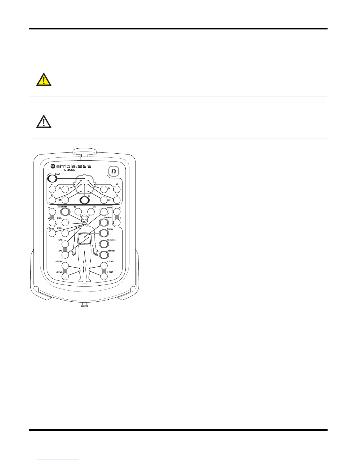
S4500 Input Panel
Status Lights
There are three status lights at the top of the Input Panel: PWR, OXI, and REC.
•PWR: Indicates the power supply. A green light indicates the unit is receiving power. If
no light is visible, the unit is not receiving power.
•OXI: Indicates the status of the connection to the oximeter. A green light indicates
connection to the oximeter. If no light is visible, the unit is not connected to the oximeter.

Embla S4500 Clinical Manual
12
•REC: Indicates the status of the recording. A green light indicates the unit is recording.
If no light is visible, the unit is not recording.
Impedance Test Button
The impedance test button is located in the top right hand corner of the Input Panel. An
impedance test can be performed when the bedside unit is recording or idle (not recording). To
save the results of the impedance test (as part of a recording), press the impedance test button
when a recording is in progress. For more information, see Testing the Electrode Impedance.
Although it is possible to test impedance using the test button on the input panel, it is
recommended that you use your Embla PSG software to test impedance. If you require
a specific impedance threshold, for example, 5kOhms (to meet AASM guidelines) you
must perform impedance testing using your Embla PSG software.
Channel Inputs
The Bedside Unit reads and transmits a total of 21 channels and includes an input for a ground
electrode (PGND) and a reference electrode. On the Embla S4500, the Reference input label
refers is CZ.
Bedside Unit

System Components
13
Referential Channels
The beside unit has 13 referential channels:
•8 channels (M1, M2, F3, F4, C3, C4, O1, O2) intended for EEG and labeled according
to the international 10-20 System of electrode placement.
•2 channels (E1, E2) intended for EOG.
•3 channels (EMG1, EMG2, EMG3) intended for chin EMG signal.
Bipolar Channels
The bedside unit has 5 bipolar channels (indicated by ± symbol).
•±EKG: intended for EKG/ECG.
•±R EMG: intended for right limb EMG.
•±L EMG: intended for left limb EMG.
•The 2 remaining channels, labeled ±1 and ±2, are extra bipolar channels.
Channel inputs on the Input Panel are intended for 1.5mm touch-proof plugs ONLY.
Sensor Input Channels
The beside unit has 6 sensor input channels: 5 respiratory data channels and 1 sensor input
channel for position. These channels have a proprietary two pin connector with different labels,
each with a unique color.
•Thermistor: intended for nasal flow (Color: gray).
•Snore: intended for snore (Color: white).
•Position: intended for body position (Color: purple).
•Thorax: intended for thoracic respiratory effort with XactTrace (Color: blue).
•Abdomen: intended for abdominal respiratory effort with XactTrace (Color: yellow).
•Oximeter: intended for oximetry data (Color: brown).
Sensor inputs on the Input Panel are intended for 2 pin touch-proof type connectors
ONLY.
Table of contents
Other Embla Medical Equipment manuals


Popular Medical Equipment manuals by other brands


Getinge
Getinge Arjohuntleigh Nimbus 3 Professional Instructions for use

Mettler Electronics
Mettler Electronics Sonicator 730 Maintenance manual

Pressalit Care
Pressalit Care R1100 Mounting instruction

Denas MS
Denas MS DENAS-T operating manual

bort medical
bort medical ActiveColor quick guide

AccuVein
AccuVein AV400 user manual


