manuals.online logo
Brands
  1. Home
  2. •
  3. Brands
  4. •
  5. Oregon Scientific
  6. •
  7. Weather Station
  8. •
  9. Oregon Scientific WMR200 User manual

Oregon Scientific WMR200 User manual

Other manuals for WMR200

4

This manual suits for next models

1

Other Oregon Scientific Weather Station manuals

Oregon Scientific BAR638HG User manual

Oregon Scientific

Oregon Scientific BAR638HG User manual

Oregon Scientific BAR339DPH User manual

Oregon Scientific

Oregon Scientific BAR339DPH User manual

Oregon Scientific RMR602A User manual

Oregon Scientific

Oregon Scientific RMR602A User manual

Oregon Scientific WMR89 User manual

Oregon Scientific

Oregon Scientific WMR89 User manual

Oregon Scientific LW301 User manual

Oregon Scientific

Oregon Scientific LW301 User manual

Oregon Scientific AWS899 User manual

Oregon Scientific

Oregon Scientific AWS899 User manual

Oregon Scientific BAR626 User manual

Oregon Scientific

Oregon Scientific BAR626 User manual

Oregon Scientific BA812E User manual

Oregon Scientific

Oregon Scientific BA812E User manual

Oregon Scientific WMR968 User manual

Oregon Scientific

Oregon Scientific WMR968 User manual

Oregon Scientific BAR800A User manual

Oregon Scientific

Oregon Scientific BAR800A User manual

Oregon Scientific BAR938HG User manual

Oregon Scientific

Oregon Scientific BAR938HG User manual

Oregon Scientific BAR338PA User manual

Oregon Scientific

Oregon Scientific BAR338PA User manual

Oregon Scientific Modena FSW-301 User manual

Oregon Scientific

Oregon Scientific Modena FSW-301 User manual

Oregon Scientific JW103 User manual

Oregon Scientific

Oregon Scientific JW103 User manual

Oregon Scientific BAR338P User manual

Oregon Scientific

Oregon Scientific BAR338P User manual

Oregon Scientific BA169 User manual

Oregon Scientific

Oregon Scientific BA169 User manual

Oregon Scientific BAR686 User manual

Oregon Scientific

Oregon Scientific BAR686 User manual

Oregon Scientific BA900 User manual

Oregon Scientific

Oregon Scientific BA900 User manual

Oregon Scientific RGR202 User manual

Oregon Scientific

Oregon Scientific RGR202 User manual

Oregon Scientific WMR500A User manual

Oregon Scientific

Oregon Scientific WMR500A User manual

Oregon Scientific BAR310HG User manual

Oregon Scientific

Oregon Scientific BAR310HG User manual

Oregon Scientific WMR180A User manual

Oregon Scientific

Oregon Scientific WMR180A User manual

Oregon Scientific BAR122HGN User manual

Oregon Scientific

Oregon Scientific BAR122HGN User manual

Oregon Scientific BAR218HG User manual

Oregon Scientific

Oregon Scientific BAR218HG User manual

Popular Weather Station manuals by other brands

Bresser 7000016000000 instruction manual

Bresser

Bresser 7000016000000 instruction manual

Auriol AHFL 433 A1 operating instructions

Auriol

Auriol AHFL 433 A1 operating instructions

Hyundai WS 2202 instruction manual

Hyundai

Hyundai WS 2202 instruction manual

NexSens G2-HYDROMET quick start

NexSens

NexSens G2-HYDROMET quick start

IROX HBVR761 UV-X user manual

IROX

IROX HBVR761 UV-X user manual

La Crosse Technology C86371 instruction manual

La Crosse Technology

La Crosse Technology C86371 instruction manual

ADE WS 1711 operating instructions

ADE

ADE WS 1711 operating instructions

WAREMA EWFS Weather station eco Operating and installation instructions

WAREMA

WAREMA EWFS Weather station eco Operating and installation instructions

Auriol z29592 Operation and safety notes

Auriol

Auriol z29592 Operation and safety notes

Auriol 296289 Operation and safety notes

Auriol

Auriol 296289 Operation and safety notes

Hyundai WS 2266 instruction manual

Hyundai

Hyundai WS 2266 instruction manual

La Crosse Technology WS-2210 Operation manual

La Crosse Technology

La Crosse Technology WS-2210 Operation manual

La Crosse Technology WS-811561 manual 

La Crosse Technology

La Crosse Technology WS-811561 manual 

Ventus W177 owner's manual

Ventus

Ventus W177 owner's manual

National Geographic VA Colour RC instruction manual

National Geographic

National Geographic VA Colour RC instruction manual

Instant Transmission MA 10410 instruction manual

Instant Transmission

Instant Transmission MA 10410 instruction manual

Lutron Electronics PHB-318 Operation manual

Lutron Electronics

Lutron Electronics PHB-318 Operation manual

La Crosse Technology WS-9118U instruction manual

La Crosse Technology

La Crosse Technology WS-9118U instruction manual

manuals.online logo
manuals.online logoBrands
  • About & Mission
  • Contact us
  • Privacy Policy
  • Terms and Conditions

Copyright 2025 Manuals.Online. All Rights Reserved.

лчиттничюнльтцию.
глтчн.Бзвыдны
www.sotmarket.ru
дбняинфмциятв,
тзывы,бзыиы
Инструкция для
Oregon Scientific WMR200
Перейти в карточку товара
8 800 775 98 98
1
EN
Professional Weather Center
Model: WMR200 / WMR200A
USER MANUAL
CONTENTS
Introduction .............................................................................................................. 1
Packaging Contents ............................................................................................... 1
Base Station ......................................................................................................... 1
Wind Sensor / Temperature & Humidity Sensor .................................................. 1
Solar Panel ........................................................................................................... 1
Rain Gauge ........................................................................................................... 1
Assembly Parts .................................................................................................... 2
Accessories - Sensors ............................................................................................ 2
Overview ................................................................................................................... 2
Front View ............................................................................................................ 2
Back View ............................................................................................................ 2
LCD Display ......................................................................................................... 2
Detailed LCD Display View ..................................................................................... 2
Barometer ............................................................................................................. 2
Rainfall .................................................................................................................. 3
UV ......................................................................................................................... 3
Clock / Moon Phase .............................................................................................. 3
Outdoor Temperature / Humidity .......................................................................... 3
Indoor Temperature / Humidity ............................................................................. 3
Wind Speed / Direction / Wind Chill ..................................................................... 3
Bar Chart ............................................................................................................... 3
Wind Sensor ......................................................................................................... 4
Rain Gauge .......................................................................................................... 4
Outdoor Temperature / Humidity Sensor ............................................................. 4
Getting Started ......................................................................................................... 4
Set Up Remote Wind Sensor ................................................................................ 4
Set Up Remote Temperature / Humidity Sensor ................................................... 4
Remote Unit Assembly ......................................................................................... 5
Alternative Set Up: Remote Wind Sensor On Existing Pole ................................ 6
Temperature / Humidity Sensor Mounted Separately ........................................... 6
Set up Rain Gauge ................................................................................................ 6
Getting Started ......................................................................................................... 7
Set up Base Station ............................................................................................. 7
Insert Batteries ..................................................................................................... 7
Sensor Data Transmission ................................................................................... 7
Clock ......................................................................................................................... 7
Clock Reception ................................................................................................... 7
Manually Set Clock .............................................................................................. 7
Pressure .................................................................................................................. 8
Set Altitude ............................................................................................................ 8
Rainfall ...................................................................................................................... 8
Accumulated Rainfall ............................................................................................ 8
UV ............................................................................................................................. 8
Weather Forecast .................................................................................................... 8
Temperature and Humidity ..................................................................................... 8
Auto Scanning Function ........................................................................................ 8
Temperature and Humidity trends ......................................................................... 8
Heat Index ................................................................................................................ 8
Wind .......................................................................................................................... 8
Moon Phase ............................................................................................................. 8
Bar Chart .................................................................................................................. 9
Alarm ........................................................................................................................ 9
Memory ..................................................................................................................... 9
MAX / MIN Records .............................................................................................. 9
Hourly Records ..................................................................................................... 9
Data Logger ......................................................................................................... 9
Set Up Software (First Time Use) ........................................................................... 9
Additional step for Windows Vista users only ....................................................... 9
Install software ...................................................................................................... 9
Disable Sleep Mode ............................................................................................... 10
To Disable Sleep Mode On Computer (Windows XP) ........................................ 10
To Disable Sleep Mode On Computer (Windows Vista) ..................................... 10
Upload data to PC software .................................................................................. 10
Software updates ................................................................................................... 10
Reset ...................................................................................................................... 10
Precautions ........................................................................................................... 10
Specifications ........................................................................................................ 10
About Oregon Scientific ....................................................................................... 11
EU-Declaration Of Conformity .............................................................................. 11
FCC Statement ...................................................................................................... 11
Declaration of Conformity .................................................................................... 11
INTRODUCTION
Thank you for selecting the Oregon Scientific™ Professional Weather Center
(WMR200 / WMR200A).
The base station is compatible with other sensors. To purchase additional sensors,
please contact your local retailer.
Sensors with this logo are compatible with this unit.
NOTE Please keep this manual handy as you use your new product. It contains
practical step-by-step instructions, as well as technical specifications and warnings
you should know about.
PACKAGING CONTENTS
BASE STATION
1 x 6V
Adapter
1 x USB
Cable
4 x AA UM-3 1.5V batteries
WIND SENSOR / TEMPERATURE & HUMIDITY SENSOR
1 x Wind Sensor (1 x
Wind Vane Above and 1
x Anemometer Below)
1 x Aluminum-pole
2 x AA UM-3 1.5V
batteries
1 x Temperature /
Humidity Sensor casing 1 x Temperature /
Humidity Sensor
2 x AAA UM-4 1.5V
batteries
1 x Sensor Connector
SOLAR PANEL
1 x Solar panel
1 x Solar panel connector
RAIN GAUGE
1 x Rain Collector
1 x Filter
2 x UM-3 / AA
4 x Screws (Type C)
6 x Washers
2
EN
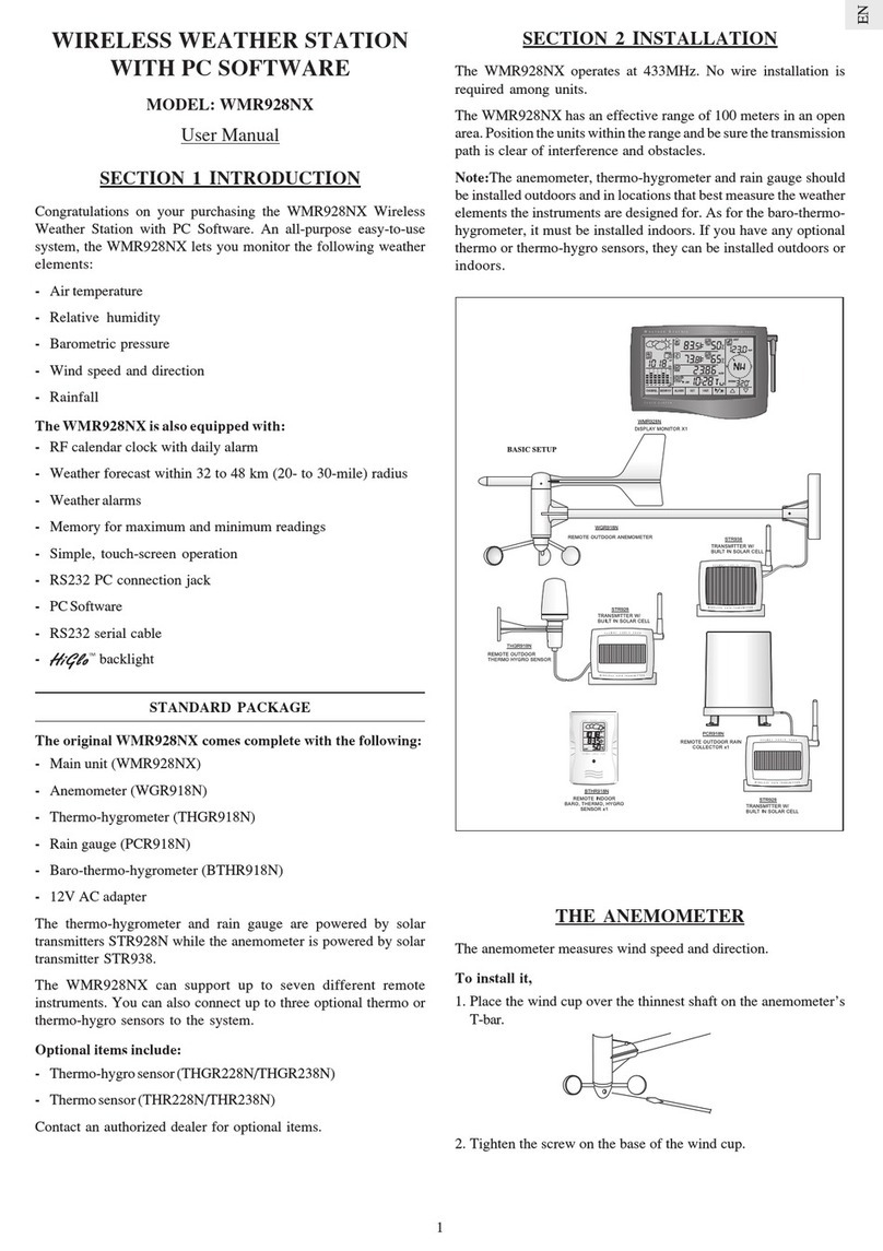
ASSEMBLY PARTS
1x Vertical
Attachment Bracket
1 x Cone-Shaped
End
1 x Horizontal
Attachment Bracket
1 x Bottom Pole 1 x Mid Pole 1x Top Pole
2 x Round U- bolts 2 x Rectangular
Base Legs
3 x Eye pins
1 x Versatile Base (Wall
or Ground Fixable)
4 x screws (Type A)
ACCESSORIES - SENSORS
This product can work with up to 10 sensors at any one time to capture outdoor
temperature, relative humidity or UV readings in various locations.
Optional wireless remote sensors such as those listed below can be purchased
separately. For more information, please contact your local retailer.*
• Thermo-hygro THGR800 (3-Ch)
• Thermo-hygro THGR810 (10-Ch)
• UV UVN800
* Features and accessories will not be available in all countries.
OVERVIEW
FRONT VIEW
21567834
1. MEM: View current, maximum and minimum readings
2. CH: Toggle between 10 different channels
3. AL: Set and view status of Clock and HI / LO alarms
4. SET: Enter setting modes
5. Antenna
6. UP / DWN: Increase / decrease the values of the selected readings
7. AL ON/OFF: Turn alarms on and off
8. UNIT: Change display units
BACK VIEW
1465723
1. USB socket
2. Backlight (continuous) On/Off
3. Battery compartment
4. AC / DC socket
5. Wall mount holes / Adjustable table stand
6. RESET: Reset unit to default settings
7. EU/UK slide switch (WMR200 only)
LCD DISPLAY
FEETM
MIN
USB218910111234567
1. Indicates a successful USB connection
2. Indicates low battery
3. Indicates no main power supply
4. Barometer area
5. Rainfall area
6. UV area
7. Clock / alarm / moon phase area
8. Weather forecast area
9. Outdoor temperature and humidity area
10. Wind area
11. Bar chart area
12. Indoor temperature / humidity area
DETAILED LCD DISPLAY VIEW
BAROMETER
FEETM12345
1. Altitude indicator
2. Altitude / pressure reading
3. 0 (current) to – 24 hours barometer record
4. Indicates pressure alarm is ON
5. User selectable altitude / pressure measurement unit
3
EN
RAINFALL
1567
8234
1. 0 (current) to – 24 hours rainfall record /
2. Accumulated total rainfall (refer to SINCE date stamp in clock area for further
details)
3. Rain rate indicator
4. Rain reading
5. Sensor batteries low
6. Indicates high rainfall alarm is ON
7. Shows accumulated rainfall of past 24 hours
8. Rainfall unit
UV
21453
1. 0 (current) to – 10 hours UV record
2. UV level index
3. Sensor batteries low
4. Indicates high UV alarm is ON
5. UVI reading
CLOCK / MOON PHASE
DATALOGGERMIN13824756
1. Displays time of records, time stamp for Indoor / Outdoor temperature / humidity
sensors and initial date set (Since date) for rainfall.
2. Radio controlled clock
3. indicates daily alarm is ON
4. Displays Clock with seconds, Clock with day, Calendar, Data logger
5. Data Logger displaying remaining number of days memory will allow for data
collection
6. Set Data Logging frequency (refer to Memory section)
7. Moon phase display
8. Offset time zone
OUTDOOR TEMPERATURE / HUMIDITY
465732111121098
1. Indicates HI / LO outdoor temperature alarms are ON
2. MAX / MIN temperatures (refer to date stamp on clock area for more details)
3. Sensor batteries low
4. Displays from 1-10 outdoor sensors
5. Heat index
6. Outdoor Temperature readings
7. Temperature trend indicators
8. Dew point temperature
9. MAX / MIN humidity
10. Indicates HI / LO outdoor humidity alarms are ON
11. Humidity trend indicators
12. User selectable temperature units
INDOOR TEMPERATURE AND HUMIDITY
45321910876
1. Indicates HI / LO temperature alarms are ON
2. MAX / MIN temperatures
3. Heat index
4. Indoor temperature reading
5. Temperature trend indicators
6. Dew point temperature
7. MAX / MIN indoor humidity
8. Indicates HI / LO humidity alarms are ON
9. Humidity trend indicators
10. User selectable temperature units
WIND SPEED / DIRECTION / WIND CHILL
123789564
1. User selectable measured winds: Gust / Average; Displays MAX wind speeds
recorded
2. Indicates HI alarm is ON
3. Sensor batteries low
4. Wind direction indicator
5. User selectable wind speed units
6. Wind speed level indicator
7. Wind chill temperature display
8. Indicates LO windchill alarm is ON
9. Windchill reading
BAR CHART
51234
1. Bar chart icon area
2. Barometer bar chart display
3. Rainfall bar chart display
4. UV bar chart display
5. Measurement axis
4
EN
WIND SENSOR
2341
1. Wind Direction
2. Wind vane casing
3. Anemometer
4. Solar power socket
RAIN GAUGE
Base and funnel:
1. Rain Gauge
2. Battery compartment
3. RESET button
1. Funnel
2. Indicator
OUTDOOR TEMPERATURE / HUMIDITY SENSOR
1234
1. Temperature / humidity sensor casing
2. Solar power socket
3. RESET button
4. Battery compartment
GETTING STARTED
SET UP REMOTE WIND SENSOR
The wind sensor takes wind speed and direction readings.
The sensor is battery and solar powered operated. It is capable of transmitting data
to the base station wirelessly within an approximate operating range of 100 meters
(328 feet).
IMPORTANT Ensure that the wind sensor is pointing North to enable it to record
accurate readings.
NOTE The sensor should be positioned in an open area away from trees or other
obstructions.
To insert batteries:
1
2
1. Unscrew the anemometer from the wind sensor carefully.
2. Insert batteries matching the polarities (+ / -) and replace the anemometer. Press
RESET after each battery change.
3
3. Slide wind vane onto the end of the plastic attachment located on the aluminium
pole.
NOTE Use alkaline batteries for longer usage and consumer grade lithium batteries
in temperatures below freezing.
SET UP REMOTE TEMPERATURE / HUMIDITY SENSOR
123
1. Holding sensor, twist and click to the left.
2. Pull sensor away from casing.
3. Insert batteries matching the polarities (+ / -). Press RESET after each battery
change.
45
4. Insert sensor into the casing, twist and click to the right to secure.
5. Slide temperature and humidity sensor onto the smaller end of the sensor connector.
5
EN
REMOTE UNIT ASSEMBLY
1
34
2
1. Insert the cone-shaped end into the pole.
2. Using 2 screws, fix it firmly into place.
3. Insert the versatile plastic base into the pole. Align the holes of the pole with the
holes of the plastic base.
4. Secure the plastic base by inserting the screw and screwing it tightly into the
holes of the plastic base and pole.
IMPORTANT The sensor
should be positioned in an open
area away from trees or other
obstructions.
5. Hammer pole (cone end down) into the ground at the desired spot until versatile
plastic base is level with the ground.
TIP Place a block of wood between the pole and the hammer to prevent damage
to the pole.
6789
6. Assemble middle pole on top of the bottom one.
7. Using two screws, fix it firmly into place.
8. Assemble top pole on top of the middle one.
9. Using two screws, fix it firmly into place.
1110
10. Slide the vertical attachment bracket on top of the top pole.
11. Using two screws, fix it firmly into place.
To mount the temperature / humidity sensor:
12
12. Slide outdoor sensor onto vertical attachment bracket.
141513
13. Slide the solar panel connector into place on the opposite side of the bracket. Slot
the solar panel in place.
14. Adjust the solar panel. Once facing desired direction, use screw to fix in place.
15. Loosen the wing bolt and adjust the angle. Tighten wing bolt to secure solar panel
at desired angle.
NOTE For best results, direct solar panel as follows:
Solar panel facing: if you reside in the:
North Southern Hemisphere
South Northern Hemisphere
To mount the wind sensor:
16
17
16. Insert the wind vane into the attachment bracket.
17. Screw aluminum pole firmly into place.
IMPORTANT For best results, point the wind vane North.
181920
18. Remove outdoor sensor from casing. Plug one solar panel cable into the socket.
19. Replace sensor into the casing.
20. Plug the other solar panel cable into the socket on the wind vane.
This will provide the sensors with an additional power supply.
NOTE There are slots to insert the solar power cables for convenient storage. There
are also fasteners to help tighten the cables.
NOTE The solar panel is an energy saving feature, which is an environmentally
friendly way to provide additional power to the sensors and prolongs battery life.
However, it cannot replace battery power entirely. Sensors can operate entirely on
battery power.
Securing the assembled remote unit:
2221
21. Insert the 2 rectangular base legs through the holes of the versatile base and
hammer down.
6
EN
22. Using the string, tie a knot on the eye pins. Hammer each eye pin into the ground
at a 90° angle.
IMPORTANT Using the fasteners, tighten the string. To tighten, pull fastener down.
To loosen, thread the string up through the fastener eyelets.
ALTERNATIVE SET UP: REMOTE WIND SENSOR ON EXISTING POLE
123
1. Secure the plastic base onto existing pole with U-bolts, washers and bolts.
2. Insert the horizontal attachment bracket into the base.
3. Using a screw, fix firmly into place.
16456
4. Insert wind sensor into the top of the bracket.
5. Using screws, fix aluminum pole firmly into place.
6. Slide outdoor sensor onto bracket.
IMPORTANT For best results, point the wind vane North.
89107
7. Slide the solar panel connector into place on the other side of the bracket. Slot
the solar panel in place.
8. Adjust the solar panel. Once facing desired direction, use screw to fix in place.
9. Loosen the wing bolt and adjust the angle. Tighten wing bolt to secure solar panel
at desired angle.
10. Remove outdoor sensor from casing. Plug one solar panel cable into the socket.
Replace sensor into the casing.
NOTE For best results, direct solar panel as follows:
Solar panel facing: If you reside in the:
North Southern Hemisphere
South Northern Hemisphere
11
11. Plug the other solar panel cables into the socket on the wind vane.
NOTE There are slots to insert the solar
power cable for convenient storage. There
are also fasteners to help tighten the
cables.
ALTERNATIVE SET UP: TEMPERATURE / HUMIDITY SENSOR
MOUNTED SEPARATELY
1. Insert 4 type A screws into the holes of the sensor connector. Screw firmly into
place, i.e., fence.
SET UP RAIN GAUGE
The rain gauge collects rain and takes readings of rainfall rate and the total rainfall
over a period of time. The sensor can remotely transmit data to the base station.
The base station and rain gauge should be positioned within an effective range:
about 100 meters (328 Feet) in an open area.
The rain gauge should be mounted horizontally about 1 meter (3 feet) from the
ground in an open area away from trees or other obstructions to allow rain to fall
naturally for an accurate reading.
To set up the Rain Gauge:
1. Remove screws and slide the cover off in an upwards motion.
2. Insert the batteries (2 x UM-3 / AA), matching the polarities (+ / -). Press RESET
after each battery change.
3. Remove the fibre tape.
To ensure a level plane:
Put a few drops of water on the cross at the base of the funnel to check the horizontal
level.
7
EN
1234
Water will pool to the center of the cross when the rain gauge is level.
If water remains on 1-4, the gauge is not horizontal.
If necessary, adjust the level using the screw.
NOTE For best results, ensure the base is horizontal to allow maximum drainage
of any collected rain.
GETTING STARTED
SET UP BASE STATION
NOTE Install batteries matching the polarities (+ / -) in the remote sensor before
installing the base station.
For continuous use, install the AC adapter. The batteries are for back-up use only.
NOTE Make sure the adapter is not obstructed and is easily accessible to the unit.
NOTE The base station and adapter should not be exposed to wet conditions. No
objects filled with liquid, such as vases, should be placed on the base station and
adapter.
INSERT BATTERIES
1. Remove the battery compartment.
2. Insert the batteries, matching the polarities (+ / -).
3. Press RESET after each battery change.
NOTE Do not use rechargeable batteries. It is recommended that you use alkaline
batteries with this product for longer performance.
NOTE Batteries should not be exposed to excessive heat such as sunshine or fire.
LOCATION MEANING
Weather forecast area Base station batteries low
Rainfall / UV / Wind / Outdoor
temperature / humidity area Sensor batteries low
SENSOR DATA TRANSMISSION
To search for a sensor:
1. Select desired area to activate.
2. Press and hold CH and MEM.
3. icons will flash for 5 minutes.
NOTE Unit will search only for already registered sensors or new sensors reset
within last 30 minutes. To register a new sensor, reset sensor prior to search.
The sensor reception icon in the remote sensor area shows the status:
ICON DESCRIPTION
Base station is searching for sensor(s)
A channel has been found
Sensor 1 data received
The sensor cannot be found.
TIP The transmission range may vary depending on many factors. You may need to
experiment with various locations to get the best results.
CLOCK
CLOCK RECEPTION
This product is designed to synchronize its clock automatically with a clock signal.
WMR200:
Slide switch to EU / UK to select the desired signal.
• EU: DCF-77 signal: within 1500km (932 miles) of Frankfurt, Germany.
• UK: MSF-60 signal: within 1500km (932 miles) of Anthorn, England.
WMR200A:
WWVB-60 signal: within 3200km (2000 miles) of Fort Collins Colorado. Manually set
clock to select time zone (Pacific, Mountain, Central or Eastern).
indicates the status of the clock reception signal.
ICON MEANING
Time is synchronized
Receiving signal is strong
Time is not synchronized
Receiving signal is weak
NOTE Reception takes 2-10 minutes. If the signal is weak, it can take up to 24 hours
to get a valid signal.
To enable / disable signal reception:
Press and hold clock area to enable / disable signal reception. A beep will
sound to confirm action.
NOTE For best reception, the base station should be placed on a flat, non-metallic
surface near a window in an upper floor of your home. The antenna should be placed
away from electrical appliances and not be moved around when searching for a
signal.
MANUALLY SET CLOCK
1. Press clock area to activate.
2. Press SET to toggle between time zone offset, 12/24 hr format, hour, minute,
year, day / month, month, day, time zone.
3. Once in desired setting, press UP or DWN to change the settings.
4. Press:
• SET to confirm and continue to next setting OR
• touch panel area (except tool bar) to confirm and exit.
WMR200: Time zone offset sets the clock +/- 23 hours from the received clock signal
time.
WMR200A: Select the time zone: (PA) Pacific, (EA) Eastern, (CE) Central or (MO)
Mountain.
NOTE The language options are English (E), German (D), French (F), Italian (I),
and Spanish (S).
8
EN
To select clock display mode:
Press clock area repeatedly to toggle between:
• Clock with seconds
• Clock with weekday
• Date with year
• Data logger (please refer to Memory / Data logger section)
PRESSURE
To toggle barometer unit:
1. Press barometer area to toggle between Altitude / current barometer.
2. Press UNIT to select FEET / M or inHg / mmHg / mb / hPA.
SET ALTITUDE
Set the altitude to reflect distance from sea level at your position.
1. Press barometer area to display ALT.
2. Press SET.
3. Press UP / DWN to set the altitude in 10 m (33 ft) increments from -100 m (-328
ft) to 2500 m (8202 ft).
4. Press SET or touch panel area (except tool bar / forecast area) to confirm.
RAINFALL
To select rainfall display mode:
Press rain area to toggle between:
• Rain rate
• Hourly Rainfall
• Accumulated rainfall
• Rainfall recorded in the past 24 hours
Press UNIT to select mm / in.
ACCUMULATED RAINFALL
To display SINCE DATE:
1. Press rain area repeatedly until Accumulated Rainfall is displayed. (Clock
area will display the start date / time of rainfall recording).
To reset SINCE DATE:
Press and hold MEM to set current time as start of accumulated rainfall records.
UV
The UV index levels are as follows:
UV INDEX DANGER LEVEL ICON
0-2 Low
3-5 Moderate
6-7 High
8-10 Very high
11 and above Extremely high
WEATHER FORECAST
This product forecasts the next 12 to 24 hours of weather within a 30-50 km (19-31
mile) radius (US- with a 75% accuracy).
Sunny
Clear night
Partly cloudy
Partly cloudy at night
Cloudy
Rainy
Snowy
TEMPERATURE AND HUMIDITY
To toggle temperature unit:
1. Press Indoor / Outdoor Temperature / Humidity area.
2. Press UNIT to select °C / °F.
To auto-scan between sensors (Outdoor):
1. Press Outdoor Temperature / Humidity area.
2. Press and hold CH to display data for each sensor.
AUTO SCANNING FUNCTION
To activate the outdoor temperature and humidity auto-scan function:
1. Press and hold CH to activate auto-scan. The temperature and humidity display
will scroll from indoor to ch1 through to ch10.
2. Press CH / MEM to stop the auto-scan.
NOTE Channel 1 is used for the outdoor temperature and humidity sensor provided in
this package. Additional temperature and humidity sensors can use other channels.
To change channel:
Press CH to change channel.
TEMPERATURE AND HUMIDITY TRENDS
The temperature and humidity trend icons are based on recent sensor readings.
The trend lines are shown next to the temperature and humidity readings. The trend
is shown as follows:
RISING STEADY FALLING
HEAT INDEX
Press Indoor / Outdoor Temperature / Humidity area to display the actual
temperature felt:
TEMPERATURE
RANGE WARNING MEANING
27°C to 32°C
(80°F to 89°F) Caution Possibility of heat exhaustion
32°C to 40°C
(90°F to 104°F) Extreme Caution Possibility of heat dehydration
41°C to 54°C
(105°F to 129°F) Danger Heat exhaustion likely
54°C to 92°C
(130°F to 151°F) Extreme danger Strong risk of dehydration / sun
stroke
NOTE Heat index is only calculated when temperature is 80° F / 27°C or above.
WIND
To select wind display mode:
Press wind area to toggle between:
• Gust
• Average
Press UNIT to select unit: knots / kph / mph / m/s.
The wind level is shown by a series of icons:
Lost
sensor Light Moderate Strong Storm
0-8 mph
(3-13 km/h)
9-25 mph
(14-41 km/h)
26-54 mph
(42-87 km/h)
>55 mph
(>88 km/h)
MOON PHASE
1. Press clock area to activate.
2. Press SET repeatedly to display Year / Calendar date.
3. Press UP / DWN to view moon phase for specific dates.
New Moon Full Moon
Waxing Crescent Waning Gibbous
First quarter Last quarter
9
EN
HOURLY RECORDS
Display Hourly readings of up to
Barometer 24 hours back
Hourly Rainfall 24 hours back
UV 10 hours back
To view hourly records:
1. Press desired area to activate.
2. Press UP / DWN to view current (0) / hourly reading.
When MAX / MIN reading is displayed, the corresponding timestamp will be
displayed in the clock area .
DATA LOGGER
To set DATA LOGGER:
1. Press clock area until DATA LOGGER mode is displayed.
2. Press SET.
3. Press UP / DWN to select frequency of data recording (1 / 2 / 5 / 10 /15).
4. Press SET.
5. The number of days memory will allow for records will be displayed.
Frequency in minutes No. of days available for data logging with Memory
available*
1 19
2 38
5 97
10 194
15 291
* based only on all provided sensors in this package being used, and after all memory
has been cleared.
To view remaining days for records:
Press clock area until DATA LOGGER mode is displayed.
NOTE When DATA LOGGER is full, i.e., no more records can be stored on unit,
‘DATA LOGGER’ and ‘O Days’ will flash.
SET UP SOFTWARE (FIRST TIME USE)
The weather station is capable of connecting to a PC computer using the USB
connection. The software can read the latest weather data collected from the base
station.
PC system requirements
The minimum system requirements for use of the software is:
• Operating system: Microsoft Windows XP SP2 or Vista
• Processor: Pentium 4 or above
• RAM: Min. 512 MB
• Hard disk free space: Min. 512 MB
• Screen Display Area:1024 x 768 pixels (recommended)
ADDITIONAL STEP FOR WINDOWS VISTA USERS ONLY
* For Windows XP users, please go straight to Install Software section.
IMPORTANT You must follow the below instructions before installing software.
Determine status of UAC (User Account Control):
1. Click on
ˇ
Start.
2. In context menu, scroll to Settings and select Control Panel.
3. Double click the User Account (and Family Safety).
4. Double click on Change your Windows password. (If you chose the Control
Panel classic link from left hand column in step 2, skip this step).
5. In Turn User Account On or Off screen, identify if UAC option is enabled / on
(ticked) or disabled / off (un-ticked).
NOTE We highly recommend disabling this option for seamless operation of
the Weather OS software.
To Turn User Account off:
6. Deselect the UAC option by un-ticking the box (click once).
7. Click OK.
8. In You must restart your computer dialogue box, click Restart now.
INSTALL SOFTWARE
1. Insert provided CD into disk drive.
2. Run CD software.
3. Setup Wizard dialogue box will appear and guide you through the installation
process.
Waxing Gibbous Waning Crescent
BAR CHART
To select chart display mode:
Press bar chart area to toggle between these chart displays:
• Barometer
• Rain
• UV
ALARM
Weather alarms are used to alert you of certain weather conditions. Once activated,
the alarm will turn off when a certain criterion is met.
Area Type of alarm
Barometer Barometer HI
Rain Rain rate HI
UV UV HI
Temperature Current Temperature HI
LO
Heat Index HI
Humidity Current Humidity HI
LO
Dew Point HI
LO
Clock Daily Alarm
Wind Gust Wind Speed HI
Low Wind Chill LO
To set the alarm:
1. Press desired area to activate.
2. Press AL to display Time and HI / LO alarm.
3. Press and hold AL
4. Press UP / DWN to set the desired values.
5. Press
• AL to confirm and continue to next setting OR
• touch anywhere on the screen (except tool bar / weather forecast area) to
confirm and exit.
To enable / disable alarms:
1. Press desired area to activate.
2. Press AL to display set Time and HI / LO alarm.
3. Press AL ON/OFF to turn alarm ON / OFF.
“- -“ indicates alarm is not set / disabled.
NOTE Clock alarm sound is different from weather alarms to allow for easy
differentiation by user.
To silence any alarm: Press anywhere on the screen.
NOTE will continue flashing, despite silenced alarm, for at least 2 minutes or
until condition ceases.
NOTE When alarm is on, the channel of triggered alarm will be displayed.
MEMORY
MAX / MIN RECORDS
Area Type of Memory
Temperature Current Temperature MAX
MIN
Heat Index MAX
MIN
Humidity Current Humidity MAX
MIN
Dew Point MAX
MIN
Wind Gust Wind Speed MAX
Wind Chill MIN
To view MAX / MIN records:
1. Press desired area to activate.
2. Press MEM to toggle between MIN / MAX recorded values.
To clear individual area records:
1. Press desired area to activate.
2. Press and hold MEM.
3. Delete process is complete when display shows current reading.