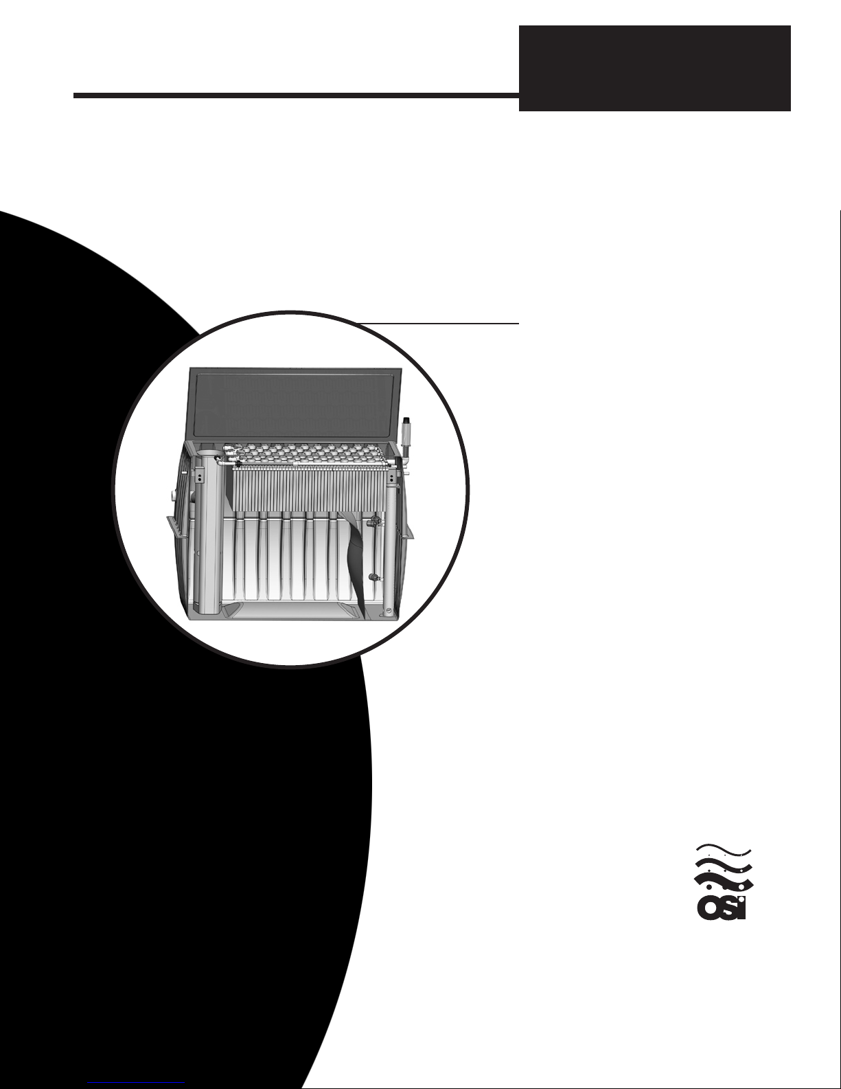
Installation Manual: AdvanTex®AX20-RT Treatment Units
NIM-ATX-AXRT-1
Rev. 1.0, 1/10
© 2010 Orenco Systems®Inc.
Table of Contents
Products described in this manual are covered by one or more of the following U.S. Patents: 6,540,920; 6,372,137; 5,531,894; 5,492,635; 5,480,561; 5,360,556;
4,439,323. Products are also covered by foreign patents.
1
Before You Begin
As the installer of an onsite wastewater treatment
system, you play a crucial role. Homeowners,
neighbors, service providers, regulators, Dealers,
manufacturers ... we all rely on your expertise
and good work. At Orenco, we’ve worked hard to
make your installation as easy and “hassle-free”
as possible.
We’re very proud of this wastewater treatment
system. Like all our products, the AdvanTex®
AX20-RT Treatment Unit has gone through
extensive research, development, and field-test-
ing. Then each component is built to written spec-
ifications and subjected to quality review before
shipping. If this system or any of its components
possesses flaws that would inhibit its proper func-
tioning, please contact your authorized AdvanTex
Dealer. The Dealer can also provide repair and replacement instructions and replacement components. If there is no
authorized AdvanTex Dealer in your area, call Orenco Systems®, Inc. at 800-348-9843 or +1-541-459-4449.
Property owners, neighbors, regulators, Dealers, manufacturers, and
service providers all depend on your careful installation.
Before You Begin ............................................................. Page 1
Overview ..................................................................... Page 3
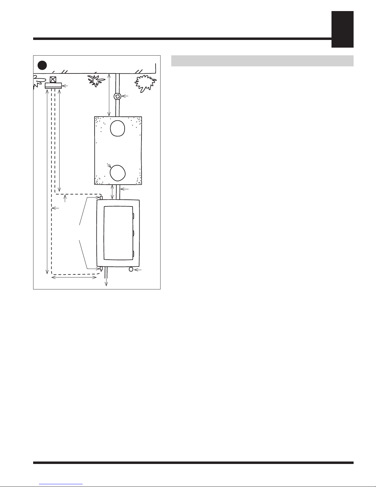
Installation Steps
Step 1: Review or Sketch Site Plans ............................................. Page 4
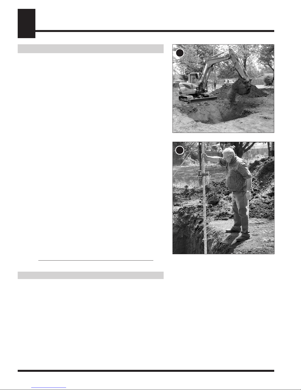
Step 2: Excavate and Set Primary Tank ........................................... Page 5
Step 3: Install Risers and Water Test Tank ......................................... Page 5
Step 4: Install Effluent Filter .................................................... Page 6
Step 5: Excavate and Set AX20-RT Unit .......................................... Page 7
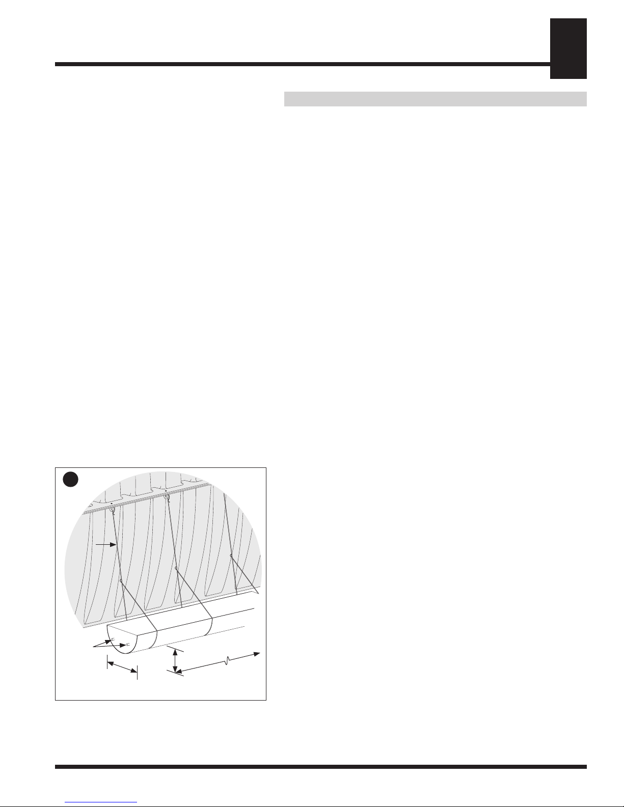
Step 6: Prep and Install Counterbuoyancy ......................................... Page 8
Step 7: Partially Backfill AX20-RT Excavation..................................... Page 9
Step 8: Test Watertightness of AX20-RT Unit ...................................... Page 9
Step 9: Connect Transport Line and Passive Air Vent ................................ Page 10
Step 10: Install and Test Control Panel ............................................. Page 11
Step 11: Test System Function ................................................... Page 14
Step 12: Complete Final Backfill ................................................. Page 15