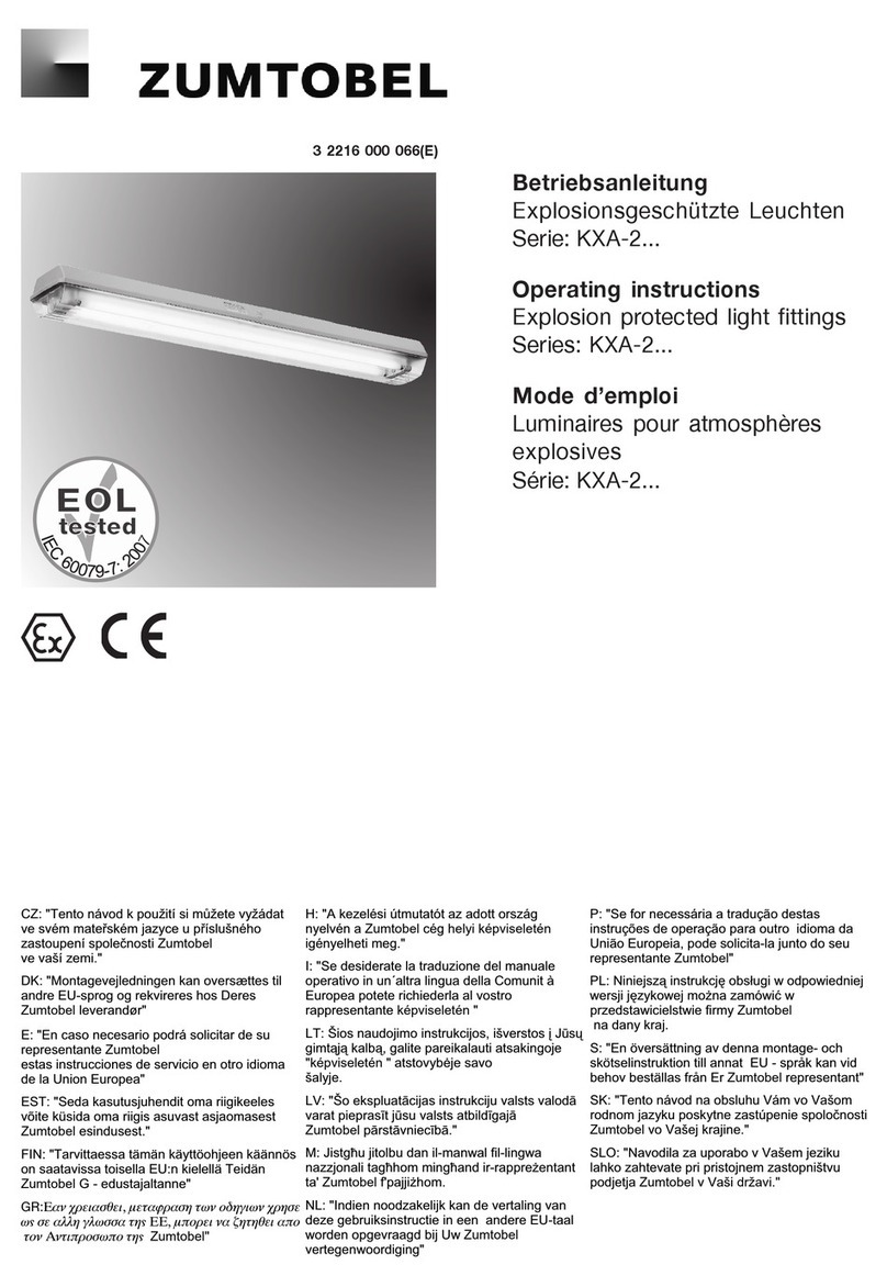
Zumtobel KXB Series User manual

Betriebsanleitung
Explosionsgeschützte Leuchten
für Zone 2 und Zone 22
Serie: KXB-.....
Operating instructions
Explosion protected light fittings
Zone 2 and Zone 22
Serie: KXB-.....
Mode d’emploi
Luminaires pour atmosphères
explosives Zone 2 et Zone 22
Serie: KXB-.....
300 8000 2080 (a) D/E/F
CZ: "Tento návod k použití si mĤžete vyžádat
ve svém mateĜském jazyce u pĜíslušného
zastoupení spoleþnosti Zumtobel
ve vaší zemi."
DK: "Montagevejledningen kan oversættes til
andre EU-sprog og rekvireres hos Deres
Zumtobel leverandør"
E: "En caso necesario podrá solicitar de su
representante Zumtobel
estas instrucciones de servicio en otro idioma
de la Union Europea"
EST: "Seda kasutusjuhendit oma riigikeeles
võite küsida oma riigis asuvast asjaomasest
Zumtobel esindusest."
FIN: "Tarvittaessa tämän käyttöohjeen käännös
on saatavissa toisella EU:n kielellä Teidän
Zumtobel G - edustajaltanne"
doW(DQFUHLDVTHLPHWDMUDVKWZQRGKJLZQFUKVH
Z9VHDOOKJOZVVDWK9((PSRUHLQD]KWKTHLDSR
WRQ$QWLSURVZSRWK9Zumtobel"
H: "A kezelési útmutatót az adott ország
nyelvén a Zumtobel cég helyi képviseletén
igényelheti meg."
I: "Se desiderate la traduzione del manuale
operativo in un´altra lingua della Comunit à
Europea potete richiederla al vostro
rappresentante képviseletén "
LT: Šios naudojimo instrukcijos, išverstos ƳJnjsǐ
gimtąjąkalbą, galite pareikalauti atsakingoje
"képviseletén " atstovybơje savo
šalyje.
LV: "Šo ekspluatƗcijas instrukciju valsts valodƗ
varat pieprasƯt jnjsu valsts atbildƯgajƗ
Zumtobel pƗrstƗvniecƯbƗ."
M: Jistgƫu jitolbu dan il-manwal fil-lingwa
nazzjonali tagƫhom mingƫand ir-rappreĪentant
ta' Zumtobel f'pajjiĪhom.
NL: "Indien noodzakelijk kan de vertaling van
deze gebruiksinstructie in een andere EU-taal
worden opgevraagd bij Uw Zumtobel
vertegenwoordiging"
P: "Se for necessária a tradução destas
instruções de operação para outro idioma da
União Europeia, pode solicita-la junto do seu
representante Zumtobel"
PL: NiniejsząinstrukcjĊobsáugi w odpowiedniej
wersji jĊzykowej moĪna zamówiüw
przedstawicielstwie firmy Zumtobel
na dany kraj.
S: "En översättning av denna montage- och
skötselinstruktion till annat EU - språk kan vid
behov beställas från Er Zumtobel representant"
SK: "Tento návod na obsluhu Vám vo Vašom
rodnom jazyku poskytne zastúpenie spoloþnosti
Zumtobel vo Vašej krajine."
SLO: "Navodila za uporabo v Vašem jeziku
lahko zahtevate pri pristojnem zastopništvu
podjetja Zumtobel v Vaši državi."

2Zumtobel Lighting GmbH
Sechskant/Hexagon... SW 13
400 (18 W)
700 (36 W)
700 (58 W)
760 (18 W)
1360 (36 W)
1660 (58 W)
732 (18 W)
1332 (36 W)
1632 (58 W)
M8, eLLK 92
12 tief/deep/
profond
1
2
1
2
Anschlußraum
für ein Kabel
Connection
compartment
for 1 cable
Compartiment
de raccordement
pour 1 câble
Anschlußraum
für zwei Kabel
Connection
compartment
for 2 cables
Compartiment
de raccordement
pour 2 câbles
Montagebilder/ Illustrations for mounting / Illustrations du montage
1
23
64 5
7 8 9
8.1 9.1
188
44 1060 (18 W), 1660 (36 W)
736 (18 W), 1336 (36 W)
33 33 150 150
20
34
188
46
65
130
76
130
4a
24
ca. 90°
ca. 90°
10
≥2 mm
11 12

Zumtobel Lighting GmbH 3
Elektrische Daten/electrical data/Caractéristiques Electriques:
Ausführung/type/Modèle 2 x 18 W 1 x 36 W 2 x 36 W 1 x 58 W 2 x 58 W
Spannungsbereich AC
Voltage range AC
Plage de tensions CA 220 - 240 V *
Frequenzbereich:
Frequency range
Plage de fréquences 50 - 60 Hz
Spannungsbereich DC
Voltage range DC
Plage de tensions CC 220 - 240 V*
cos ϕ ( 230 V): 0,97 cap. 0,97 cap. 0,97 cap. 0,97 cap 0,95 cap.
Nennstrom in A
Rated current in A
courant nominal en A 0,16A (0,19) 0,16A 0,28A (0,35) 0,24A 0,45A (0,55)
KXB--2 .
1 Lampe je EVG/1 lamp each EVG/1 Lampe par EVG
KXB ... (2 Lampen je EVG/2 lamps each EVG/2 Lampes par EVG)
Schaltpläne / Wiring diagrams / Schémas de connexions
siehe auch Typschild/see also type lable/voir le signe de type
* zulässige Toleranzen gemäß EN 50014/max. permissable tolerances accd. EN 50014/
Tolerances admissible selon EN 50014

4Zumtobel Lighting GmbH
1. Sicherheitshinweise
Zielgruppe:
Elektrofachkräfte und unterwiesene
Personen.
Beachten Sie die nationalen Unfall-
verhütungs- und Sicherheitsvorschriften
und die nachfolgenden Sicherheitshin-
weise, die in dieser Betriebsanleitung mit
einem ( ) gekennzeichnet sind!
UDiese Leuchte darf nicht in explosions-
gefährdeten Bereichen der Zonen 0, 20, 1 und
21 eingesetzt werden!
UDas Betriebsmittel darf nicht bei Staubab-
lagerungen übermäßiger Dicke (≥50 mm,
gem. EN 50281-1-2) betrieben werden.
UDie auf der Leuchte angegebenen technischen
Daten sind zu beachten!
UUmbauten oder Veränderungen an der Leuchte
sind nicht zulässig!
UDie Leuchte ist bestimmungsgemäß in
unbeschädigtem und einwandfreiem Zustand zu
betreiben!
UAls Ersatz dürfen nur Originalteile von Zumtobel
verwendet werden!
UReparaturen dürfen nur von Zumtobel oder einer
qualifizierten „Elektrofachkraft“ durchgeführt
werden!
UBetriebsanleitung während des Betriebes nicht
in der Leuchte belassen!
Prüfdrehmoment für Kabel- und Leitungs-
einführung M25 x 1,5: 5,0 Nm
Prüfdrehmoment für Druck-
schraube: 3,5 Nm (für Abdich-
tung Leitung oder
Verschlußstopfen)
Leuchten- und Montage-
abmessungen: siehe Bild 1
Leuchtengewichte
KXB 2/18: ca. 4,0 kg
KXB 1/36: ca. 6,0 kg
KXB 2/36: ca. 6,0 kg
KXB 1/58: ca. 7,3 kg
KXB 2/58: ca. 7,3 kg
4. Installation
Die für das Errichten und Betreiben von
elektrischen Betriebsmitteln geltenden
Sicherheitsvorschriften und des Gerätesicherheits-
gesetzes sowie die allgemein anerkannten Regeln
der Technik sind einzuhalten! Transport und
Lagerung der Leuchte ist nur in Originalverpackung
und in angegebener Lage gestattet!
Öffnen und Schließen der Leuchte:
UDen Zentralverschluß mit Steckschlüssel
(Schlüsselweite SW 13) um ca. 90º bis zur
Raststellung drehen und Schutzwanne abklappen,
siehe Bild 2.
USchutzwanne ein- und ausbauen, siehe Bild 6 und
7.
UDie Schutzwanne ist wahlweise beidseitig
scharnierbar.
USchutzwanne zum Verschließen der Leuchte fest
an das Leuchtengehäuse
andrücken und den
Zentralverschluß um 90º drehen.
Montageabmessungen: siehe Bild 1
Achten sie auf die plane Anbringung der Leuchte
zur Sicherstellung der Schutzart, siehe Bild 10-12!
Beachten Sie beim Befestigen des Montagezubehörs
an der Leuchte die max. Gewindetiefe der Montage-
bohrung von 12 mm! Verwenden Sie keine zu langen
Schrauben!
Achtung!
Zeigt der Lichtaustritt nach oben, sind
zusätzliche Schutzmaßnahmen gegen
dauerhafte Wasseransammlungen im Bereich der
Wannendichtung zu treffen.
Montagezubehör:
siehe Zumtobel Katalog.
Netzanschluss KXB .... :
Zum Öffnen des Anschlußraumes grünen Drehgriff in
Pfeilrichtung bis zum Anschlag drehen, dann ziehen
und die Klappe abklappen, siehe Bild 3 + 4.
UDie Leitungen sind durch die Kabel- und
Leitungseinführung einzuführen, siehe Bild 5.
UFür Leitungen von 8 bis 12 mm sind beide
Dichtungseinsätze - von 12 bis 17 mm ist nur der
äußere Dichtungseinsatz zu verwenden. Der
korrekten Sitz des verbleibenden
Dichtungseinsatzes in der Verschraubung muß
sichergestellt sein.
UDie abisolierten Leitungen gem.
Klemmenbezeichnung (siehe Schaltplan, Seite 3)
sind in die Steckklemmen einzuführen.
Abisolierlänge 2,5 mm²:8 - 9 mm
Sind Schraubklemmen vorhanden, müssen auch
nicht benutzte Klemmen angezogen werden! Bei
Einfachbelegung der Klemmen kein Umbiegen
(Schlaufe) der Adern notwendig!
Achtung:
Bei nicht benutzten Kabel-und Leitungs-
einführungen ist die Schutzscheibe zu
entfernen und durch einen Verschlußstopfen
(Prüfdrehmoment 3,5 Nm) zu verschließen.
Beim Verschließen mit einem Verschlußstopfen stets
beide Dichtungseinsätze verwenden!
Einsetzen der Lampen:
Es dürfen nur solche Lampen, die für diese
Leuchten zugelassen sind verwendet werden
(siehe technische Daten und Typenschild)!
Die Zweistiftsockellampe (G13) in beide Fassungen bis
zum Anschlag einstecken, so daß an jeder Seite der
Lampe beide Stifte im Eingriff der Fassung sind. Da-
nach die Lampe in Raststellung drehen, siehe Bild 8.
2. Normenkonformität
Diese explosionsgeschützte Leuchte entspricht den
Anforderungen den EG-Richtlinien „Geräte und
Schutzsysteme zur bestimmungsgsmäßen Verwen-
dung in explosionsgefährdeten Bereichen“ (94/9/EG)
und „Elektromagnetische Verträglichkeit“ (2004/108/
EG). Sie wurde entsprechend dem Stand der Technik
und gemäß DIN EN ISO 9001:2000 entwickelt,
gefertigt und geprüft. Diese Leuchte ist zum Einsatz
in explosionsgefährdeten Bereichen der Zone 2 und
22 gemäß EN 60079-14 und IEC 61241-10 geeignet.
3. Technische Daten:
Leuchten mit Zweistiftlampenfassung G13:
KXB 2/18 2 x 18 W
KXB 1/36 1 x 36 W
KXB 2/36 2 x 36 W
KXB 1/58 1 x 58 W
KXB 2/58 2 x 58 W
Kennzeichnung nach
94/9/EG und Norm: II 3 G Ex nA II T4
II 3 D Ex tD A22 IP66 T 80°C
Lampenbestückung:
Leuchtstofflampen mit Zweistiftsockel G13 nach:
18 W IEC 60081-22/20
36 W IEC 60081-24/20
58 W IEC 60081-21/22
Schutzart nach EN 60 529
(IEC 60 529): IP 65
Schutzklasse nach
EN 60 598: I
zul. Umgebungs-
temperatur1): -20 °C ... +40 °C
Lagertemperatur in
Originalverpackung: -40 ºC ... +60 ºC
Klemmvermögen
Steck-Anschlußklemme: 2 x 2,5 mm²
Klemmvermögen Schraub-Anschluss-
klemme 2x je Klemme: einadrig mehradrig
min.: 1,5 mm22,5 mm2
max.: 6,0 mm24,0 mm2
Leiterquerschnitt bei Durchgangs-
erdrahtung: 2,5 mm2für max. 16A
Leitungseinführung
Kunststoff: M25 x 1,5 für Leitun-
gen Ø 8 bis 17 mm
Metallgewinde: M20 x 1,5
1) Intensive Sonneneinstrahlung in Regionen mit hohen
Umgebungstemperaturen kann im Leuchteninneren zu
unzulässig hohen Erwärmungen führen. Eine
Reduzierung der Lebensdauer des EVGs kann eine
Folge hiervon sein. Zur Vermeidung sollten in diesen
Regionen tagsüber die Leuchten über einen
Lichtsensor geschaltet werden.
Achtung! Lampenwechsel nur im ausgeschal-
teten Zustand.
Option: automatische Abschaltung über 2-poligen
Leuchtenschalter beim Öffnen der Schutzwanne.
5. Inbetriebnahme
UVor der Inbetriebnahme ist die korrekte Funktion
und Installation der Leuchte in Übereinstimmung
mit dieser Betriebsanleitung und anderen
zutreffenden Bestimmungen zu überprüfen!
UIsolationsmessungen dürfen nur zwischen PE und
Außenleiter • L1 (L2, L3) sowie zwischen PE und N
durchgeführt werden!
- Meßspannung: max. 1kVAC/DC
- Meßstrom: max. 10 mA
UDie Leuchte darf nur verschlossen betrieben werden
6. Instandhaltung
Die für die Instandhaltung, Wartung und Prü-
fung die geltenden Bestimmungen sind einzu-
halten (zum Beispiel IEC 60079-17).
Wartung
Im Rahmen der Wartung sind vor allem die Teile, von
denen die Schutzart abhängt, zu prüfen z.B.:
UGehäuse und Schutzwannen auf Risse und
Beschädigungen.
UDichtungen auf Beschädigungen.
UKlemmen, Verschraubungen und
Verschlußstopfen auf festen Sitz.
UWegen der Gefahr elektrostatischer Aufladung darf
die Leuchte nur mit einem feuchten Tuch oder
Schwamm gereinigt werden! Benutzen Sie dazu nur
übliche Haushaltsspülmittel in Verdünnung mit
Wasser! Die Wassertemperatur darf maximal 50°C
betragen. Spülen Sie anschließend mit klarem
Wasser nach, da sonst Spannungsrisse in der
Schutzwanne entstehen können!
UBeachten Sie für den Lampenwechsel die
Wechselintervalle gemäß Vorgabe der
Lampenhersteller!
Instandsetzung
Vor dem Austausch oder der Demontage von
Einzelteilen ist folgendes zu beachten:
Schalten Sie das Betriebsmittel vor dem Öffnen oder
vor Instandhaltungsarbeiten erst spannunsfrei!
Verwenden Sie nur Zumtobel Originalersatzteile
(siehe Zumtobel Ersatzteilliste)!
Programmänderungen und Ergänzungen sind vorbe-
halten.
Bei der Entsorgung nationale Abfallbeseitigungs-
vorschriften beachten!
Die Kunststoffmaterialien sind mit Material-
bezeichnungen versehen.

Zumtobel Lighting GmbH 5
1. Safety instructions:
For skilled electricians and trained person-
nel in accordance with national legislation, including
the relevant standards and, where applicable, in
acc. with IEC 60079-17 on electrical apparatus for
explosive atmospheres.
UThe light fitting is not suitable for use in
hazardous areas of zone 0 , zone 1 and zone 20!
UThe light fitting must not be use while
excessive deposit of dust (≥ 50 mm, accd. EN
50281-1-2) exist.
UThe technical data indicated on the light fitting
are to be observed!
UChanges of the design and modifications to the
light fitting are not permitted!
UThe light fitting shall be operated as intended
and in undamaged and perfect condition!
UOnly genuine Zumtobel spare parts may be
used for replacement!
URepairs may only be carried out by Zumtobel or
a qualified “electrician”!
UDo not keep these operating instructions inside
the light fitting during operation!
The national safety rules and regulations for
prevention of accidents and the following safety
instructions which are marked with an ( ) in
these operating instruction, will have to be
observed!
Test-torque for pressure
screw: 3.5 Nm (for sealing off
the cable or the
blanking plug)
Dimensions of light fittings
and for mounting: see fig. 1
Weight of light fittings:
KXB 2/18: appx. 4.0 kg
KXB 4/36: appx. 6.0 kg
KXB 2/36: appx. 6.0 kg
KXB 1/58: appx. 7.3 kg
KXB 2/58: appx. 7.3 kg
4. Installation
Observe the respective national regulations as
well as the general rules of engineering which
apply to the installation and operation of elec-
trical apparatus! Transport and storage of the
luminaire is permitted in original packing and speci-
fied position only!
Opening and closing the light fitting
UTurn the central locking device with a box
spanner (opening of the spanner SW 13) through
90° to its lock-in position and fold down the
protective bowl, see fig. 3+4.
UFit in and remove the protective bowl acc. to fig.
6 and 7.
UThe protective bowl can, at option, be hinged on
either side.
UTo close the light fitting, press the protective bowl
tightly onto the luminaire housing and turn the
central locking device through 90°.
Mounting: see fig. 1
The integrity of the fitting may be compromised if
the fixing centres are not correctly aligned, see
fig. 10-12. When fixing the mounting
accessories onto the light fitting, observe the max.
depth of thread of 12 mm!
Do not use too long screws!
Installing the light output upwards additional
protection has to be assembled to avoid
permanent water accumulations at the protective
bowl gasket area.
Accessories for mounting
See Zumtobel catalogue.
Mains connection KXB ...
To open the connection box, turn the green handle to
its stop in the direction of arrow, then pull it and fold
down the flap, see fig. 4+5.
UIntroduce the cable through the cable entry, see
fig. 5.
UUse both sealing inserts for cables from 8 to 12
mm, and the outer sealing insert only for cables
from 12 to 17 mm. Pay attention to the proper fit
of the sealing insert remaining in the cable gland.
UPlug the bared conductors to the terminals in
accordance with the terminal marking (see wiring
diagram, page 2).
stripping length 2.5 mm²: 8 - 9 mm
When screw-terminals are used also tighten vacant
terminals! With single connection of the terminal no
bending (loop) of the conductor required!
Attention
In case of unused cable entries, remove their
protective cover and close the entries with a
blanking plug (test-torque of 3.5 Nm). When
closing the gland with a blanking plug, always use
both sealing inserts!
Fitting the lamps
Only use such lamps that have been certified
for these light fittings, see Technical data and
type label!
The bi-pin lamp (G13) is to be inserted to its stop into
both holders so that both pins on either side of the
lamp engage in the holder. Then turn the lamp to its
lock-in position, see fig. 8.
Attention! Lamp exchange must be carried out while
energy is switched off.
2. Conformity with standards:
This explosion protected light fitting meets the
requirements of the EC directive „Apparatus and
protective systems for its intended use in hazardous
areas (94/9/EC) and electromagnetic compatibility
(2004/108/EEC).
It has been designed, manufactured and tested
according to the state of the art and according to DIN EN
ISO 9001: 2000. The light fitting is suitable for use in
hazardous areas of zones 2 and 22 according
IEC 60079-14 and IEC 61241-10.
3. Technical data
Light fittings with G13 bi-pin cap
KXB 2/18 2 x 18 W
KXB 1/36 1 x 36 W
KXB 2/36 2 x 36 W
KXB 2/58 1 x 58 W
KXB 2/58 2 x 58 W
Marking accd 94/9/EC. II 3 G Ex nA II T4
and standard: II 3 D Ex tD A22 IP66 T 80°C
Lamps to be fitted:
Fluorescent lamps with G13 bi-pin cap to:
18 W IEC 60081-22/20
36 W IEC 60081-24/20
58 W IEC 60081-21/22
Protection acc. to EN 60 529
(IEC 60 529): IP 65
Insulation class to
EN 60 598: I
max. permissable ambient
temperature: -20 °C to + 40 °C
Storage temperature in
original packing: -40 °C to + 60 ºC
Supply terminal clamping capacity per clamp-
terminal (2.5 mm²): 2 x 2.5 mm2
Supply terminal clamping capacity
2 x per screw-terminal: single-wire multi-wire
min. 1.5 mm22.5 mm2
max. 6.0 mm24.0 mm2
Conductor cross-section with
through-wiring: 2.5 mm2for max. 16 A
Cable entries
moulded plastics: M25x1.5 for cable
Ø 8 to 17 mm
Metal entries: M 20 x 1.5
Test-torque for M25 x 1,5
cable entry: 5.0 Nm
1) Intensive sun radiation in areas of high ambient
temperatures may cause inadmissible temperature
rise inside of the luminaire. This may result a
decrease in lifetime of the electronic ballast (EVG).
Therefore those luminaires should be switched off
during daytime by a photocell control.
5. Taking into operation
UPrior to operation, check the light fitting for its
proper functioning and installation in compliance
with these operating instructions and other
applicable regulations!
UOnly carry out insulation measurements between
PE and the external conductor L1(L,L2,L3) as well
as between PE and N!
- measuring voltage: max. 1 kV AC/DC
- measuring current: max. 10 mA
6. Maintenance
Observe the national regulations applicable to
the maintenance, servicing and test of elec-
trical apparatus as well as the general rules of engi-
neering (e.g. IEC 60079-17)!
Servicing
When servicing, in particular those components that
affect the type of protection, will have to be checked,
e. g.:
UHousing and protective bowl for any cracks or
damages.
UGaskets for their perfect condition.
UTerminals and blanking plugs for their firm fit. •
UBecause of the risk of an electrostatic charge,
the light fitting shall only be cleaned with a damp
cloth or sponge!
Only use customary household washing-up liquid
diluted in water as specified! The water
temperature may be max. 50ºC. After that, rinse
with clear water to prevent the risk of tension
cracks in the protective bowl!
ULamp replacement: Keep replacement intervals
as specified by the lamp manufacturer!
Repair
Prior to replacing or removing any compo-
nents, observe the following:
Cut the apparatus off the voltage before open-
ing it or carrying out repairs! Only use certified
genuine Zumtobel spare parts! (See Zumtobel spare
parts list).
Subject to alteration or supplement of this product
series.
Regarding waste disposal, observe the relevant
national regulations! All components are marked with
relevant material signs.

6Zumtobel Lighting GmbH
1. Consignes de sécurité
Pour le personnel électricien qualifié et
le personnel instruit suivant la
règlementation légale, y compris les
normes respectives ainsi que, le cas échéant, CEI
60079-17 pour apppareils électriques utilisables en
atmosphère explosive.
UCe luminaire ne convient pas a l’emploi en
atmosphère explosive de zones 0 et 1!
UL’appareil ne doit pas être mis en marche
lorsque l’épaisseur du dépôt de poussière est
trop importante (supérieur ou égal à 50 mm,
selon EN 50281-1-2).
ULes caractéristiques techniques indiquées sur
le luminaire doivent être respectées!
UIl n’est pas permis de transformer ou de
modifier le luminaire!
ULe luminaire ne doit être exploité que pour la
fonction qui lui est dévolue et qu’en état intact
et parfait!
USeules des pièces de rechange d’origine
Zumtobel doivent être employées pour le
remplacement!
UDes réparations ne doivent être exécutées que
par Zumtobel ou par un «électricien» qualifié!
UCe mode d’emploi ne doit pas être laissé dans
le luminaire pendant son exploitation!
Veuillez respecter les prescriptions nationales de
sécurité et de prévoyance contre les accidents
ainsi que les consignes de sécurité qui sont
marquées d’un ( ) dans ce mode d’emploi!
Entrées de câble
en métal: M20 x 1,5
Couple pour l’entrée de câble
M25 x 1,5: 5,0 Nm
Couple pour la vis de
pression: 3,5 Nm (pour étan-
cher le câble ou le
bouchon de ferme-
ture)
Dimensions des luminaires
et de fixation: voir fig. 1
Poids des luminaires
KXB 2/18: env. 4,0 kg
KXB 1/36: env. 6,0 kg
KXB 2/36: env. 6,0 kg
KXB 1/58: env. 7,3 kg
KXB 2/58: env. 7,3 kg
4. Installation
Lors de l’installation et de l’exploitation des
appareils électriques, les règlements nationaux
ainsi que les règles de la technique généralement
reconnues doivent être respectés!
Le transport et le stockage ne sont permis que dans
l’emballage original et dans la position spécifiée!
Ouverture et fermeture du luminaire:
UTourner le verrou central avec la clé â douille
(ouverture de clé SW 13) de 90º dans sa position
de crantage et rabattre la vasque de protection,
voir fig. 3 et 4.
UMonter et démonter la vasque de protection
suivant fig. 6 et 7.
ULa vasque de protection est pourvue d’une
charnière des deux côtés ce qui permet de la
suspendre de chaque côté.
UPour fermer le luminaire, presser la vasque de
protection contre le boîtier
du luminaire et tourner le verrou central de 90º.
Dimensions de fixation
Dimensions de fixation: voir fig. 1
L'intégrité de l'ajustage de précision peut être
compromise si les centres de réparation ne
sont pas correctement alignés, voir fig. 10-12.
Respecter lors de la fixation des accessoires de
montage au luminaire que les trous de fixation
doivent avoir une profondeur du pas de 12 mm au
maxi.
Si le luminaire est installé avec la vasque vers
le haut, des précautions devront être prises
pour éviter l’accumulation d’eau au niveau du joint
de la vasque.
Ne pas utiliser de vis trop longues!
Accessoires pour le montage
voir le catalogue Zumtobel.
Branchement sur secteur KXB ...:
Afin d’ouvrir la boîte de connexion, tourner la poignée
rouge jusqu’à sa butée, puis la tirer et rabattre la
trappe, voir Introduire le câble par l’entrée de câble,
voir fig. 4 et 5.
UIntroduire le câble par l’entrée de câble, voir fig. 5.
UUtiliser les deux joints d’étanchéité pour les
câbles de 8 à 12 mm, et le joint extérieur seul
pour les câbles de 12 à 17 mm. Veiller au propre
logement du joint d’étanchéité demeuré dans la
presse-étoupe.
UConnecter les câbles aux bornes PE,N,L1,(L2,L3)
suivant le repérage des bornes (voir schéma des
connexions sur page 3).
Dénudage des conducteurs: 8 - 9 mm
En cas d'occupation simple de la borne, il n'est
pas nécessaire de replier le conducteur (boucle!)
Serrer aussi les bornes non utilisées!
Attention:
En cas d’entrées de câble non utilisées, leur
disque protecteur doit être enlevé, et l’entrée
doit être fermée avec un bouchon de fermeture
(couple de 3,5 Nm). Lorsqu’ un bouchon de
fermeture est mis, toujours utiliser les deux joints
d’étanchéité!
2. Conformité avec les normes:
Ce luminaire pour atmosphère explosive correspond
aux exigences de la aux règles (instructions) de CE
„appareils et systemes protégés pour l’emploi déter-
miné en atmosphère explosive“ (94/8/CE) et
compatibilité electromagnetique (89/336/CEE).
Il a été conçu, construit et testé selon l’état actuel de
la technique et selon DIN EN ISO 9001:2000.
Ce luminaire convient a l’utilisation en atmosphère
explosive de zones2, 21 et 22 selon EN 60079-14 et
CEI 61241-10.
3. Caractéristiques techniques:
Luminaires avec douille de lampe double broche G13
KXB 2/18: 2 x 18 W
KXB 1/36: 1 x 36 W
KXB 2/36: 2 x 36 W
KXB 1/58: 1 x 58 W
KXB 2/58: 2 x 58 W
Marquage selon directive 94/9/CE
et normes: II 3 G Ex nA II T4
II 3 D Ex tD A22 IP66 T 80°C
Lampes â
utiliser:
Lampes fluorescentes â culot double broche: G13
selon 18 W CEI 60081-22/20
36 W CEI 60081-24/20
58 W CEI 60081-21/22
Indice de protection selon
EN 60 529 (CEI 529): IP 65
Classe d’isolation selon
EN 60 598: I
Température ambiante
admissible 1): -20 °C â +40 °C
Température de stockage dans
l’emballage original: -40 ºC â +60 ºC
Capacité de serrage des bornes sans vis, 2 x par
bornes 2,5 mm²: 2,5 mm2
2 x par bornes à visser: unifilaire multifilaire
min. 1,5 mm22,5 mm2
max. 6,0 mm24,0 mm2
Section transversale du conducteur en cas d’inter-
connexion: 2,5 mm2pour
16A au maxi
Entrée de câble
en plastique: modèle standard
M25x1,5 pour câbles
d’un Ø de 8 â 17 mm
1) Le rayonnement solaire intensive dans des régions
à température ambiante élevée peut provoquer à
l’intérieur du luminaire un échauffement extensif.
Ceci peut impliquer une réduction de durée de vie
considérable. Pour pallier à cela, il est préconiser
d’utiliser un interrupteur photoélectrique.
Mise en place de la lampe
N’utiliser que des lampes homologuées pour
ces luminaires, voir Caractéristiques
techniques et plaque signalétique!
Introduire la lampe double broche (G13) jusqu’à sa
butée dans les deux douilles de manière que les deux
broches de chaque côté de la lampe soient prises par
la douille. Puis tourner la lampe en position de
crantage selon fig. 9.
Attention! Remplacement de la lampe
uniquement hors tension!
5. Mise en service
UAvant la mise en service des luminaires, il faut
vérifier s’ils sont branchés et fonctionnent en
conformité avec ce mode d’emploi et avec
d’autres règlements applicables!
UDes mesures d’isolation ne doivent être
effectuées qu’entre PE et le conducteur extérieur
L1(L2,L3) ainsi qu’entre PE
et N!
- tension de mesure: 1 kV CA/CC au maxi
- courant de mesure: 10 mA au maxi
6. Entretien:
En ce qui concerne l’entretien, le test et la
ré•paration des appareils électriques pour
atmosphère explosive, les règlements
nationaux y applicables par exemple CEI 60079-17
ainsi que les règles de la technique généralement
reconnues devront être respectés!
Entretien
ULors de l’entretien surtout les composants dont
dépend le mode de protection, doivent être
vérifié, par ex.:
ULe boîtier et la vasque de protection présentent-
ils des fissures ou des signes d’avarie?
ULes joints d’échantéité sont-ils efficaces?
ULes bouchons d’obturation et les bornes sont-ils
bien serrés?
UVu le risque d’une charge électrostatique, le
luminaire ne doit être nettoyé qu’avec un chiffon
humide et non fibreux ou qu’avec une éponge!
Utiliser uniquement un détergent ménager dilué
avec de l’eau comme prescrit! La température de
l’eau ne doit pas dépasser 50 °C au maxi. Rincer
ensuite à l’eau claire afin d’éviter que
n’apparaissent des fissures dues à la contrainte
exercée sur la vasque de protection
URemplacement de la lampe: Respecer les
intervalles de remplacement selon L'indication du
fabricant de lampes!
Réparation
Avant de remplacer ou d’enlever des
composants, il faut observer le mode suivant:
Mettre l’appareil hors tension avant de l’ouvrir ou de
le réparer! N’utiliser que des pièces de rechange
approuvées d’origine Zumtobel ! (Voir liste des
pièces de rechange Zumtobel)
Sous réserve de modification ou de supplément de
cette série de produits.
Quant à l’enlèvement des déchets, veuillez respecter
la règlementation nationale en vigueur!
Quant à l’enlèvement des déchets, veuillez respecter
les règlements nationaux respectifs!
Zumtobel Lighting GmbH 7

300 8000 2080 (a) /xx/39.08/MS
Technische Änderungen vorbehalten!
Betriebsanleitung gültig ab 09.2008
Zumtobel Lighting GmbHZumtobel Lighting GmbH
Zumtobel Lighting GmbH
Schweizer Strasse 30
A-6851 Dornbirn
Tel. +43 5572 390-0
Fax. +43 5572 20721
Internet: www.zumtobel.com
E-Mail: [email protected]
This manual suits for next models
5
Table of contents
Languages:
Other Zumtobel Lighting Equipment manuals

Zumtobel
Zumtobel ARC WW T16 W Series User manual

Zumtobel
Zumtobel ONLITE central CPS K User manual

Zumtobel
Zumtobel LM-4UAS User manual

Zumtobel
Zumtobel ONLITE central User manual

Zumtobel
Zumtobel KXB S EVG ZONE2/22 BODY User manual

Zumtobel
Zumtobel DIMLITE User manual

Zumtobel
Zumtobel ALVA User manual

Zumtobel
Zumtobel EINGIESSGEH 344 ST Series User manual

Zumtobel
Zumtobel SUPER-P Series User manual

Zumtobel
Zumtobel SensControl User manual