9
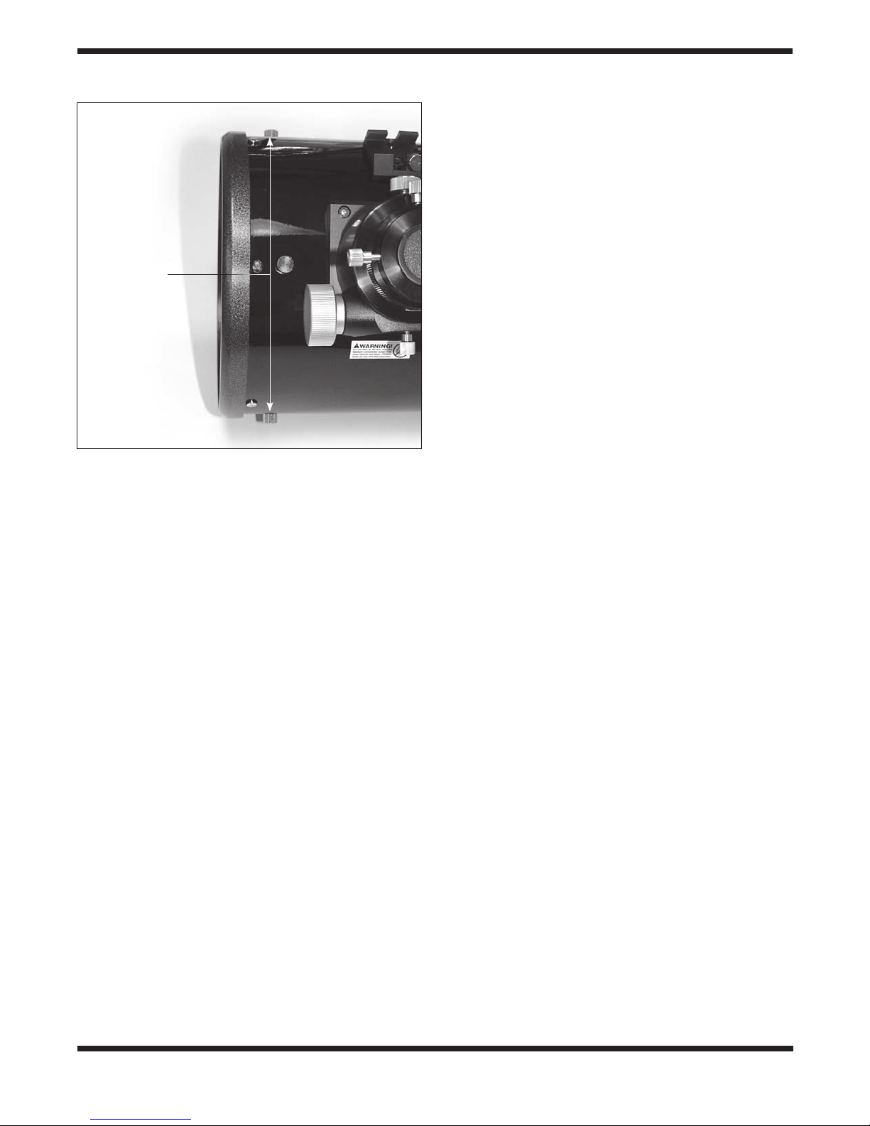
By “radial position” we mean the position of the secondary
mirror along the axis perpendicular to the focuser drawtube,
as shown in Figure 13. This position is changed by adjusting
two of the spider vane thumb nuts, as shown. Loosen one
thumb nut, then tighten the opposite one until the second-
ary mirror is centered radially in the drawtube. Do not loosen
the thumb nuts too much, to avoid having them completely
unthread from the ends of the spider vanes. Also, when mak-
ing this adjustment, be careful not to stress the spider vanes
or they could bend.
Adjusting the Secondary Mirror’s
Rotational Position
The secondary mirror should face the focuser squarely. If the
mirror appears to be rotated away from the focuser, the mir-
ror’s rotational position will need to be adjusted. Again, this
adjustment will rarely, if ever, need to be done.
Grip the sides of the secondary mirror holder with your fin-
gers. Then, using a large Phillips screwdriver, loosen the cen-
ter screw in the secondary mirror holder about a quarter of a
turn only (counterclockwise). That should be enough to free
up the secondary mirror to rotate slightly in either direction.
Look into the collimation cap and rotate the mirror slightly in
each direction to get an idea of how it affects the view of the
secondary mirror. Now rotate the mirror as needed so that it
precisely faces the focuser. Hold the mirror holder stationary
in that position while turning the center screw clockwise until
it is just tight (do not over-tighten). Sometimes the mirror may
rotate slightly when tightening the screw, so keep at it until the
mirror faces the focuser squarely and is secured in place.
Adjusting the Secondary Mirror’s Tilt
Finally, the tilt of the secondary mirror may occasionally
require adjustment. If the entire primary mirror reflection is
not visible in the secondary mirror when using the collima-
tion cap, as in Figure 9c, you will need to adjust the tilt of
the secondary mirror. Using a small Phillips head screwdriver,
first loosen one of the three alignment set screws by, say, one
full turn, and then tighten the other two to take up the slack.
Do not loosen the center screw during this process. The goal
is to center the primary mirror reflection in the secondary mir-
ror, as in Figure 9d. When it is centered, you’re done adjust-
ing the secondary mirror. Don’t worry that the reflection of the
secondary mirror (the dark circle with the four spider vanes
adjoining it) is off-center, since that adjustment is made when
aligning the primary mirror in the next step.
Aligning the Primary Mirror
The final collimation adjustment is made to the primary mir-
ror. It will need adjustment if, as in Figure 9d, the secondary
mirror is centered under the focuser and the reflection of the
primary mirror is centered in the secondary mirror, but the
reflection of the secondary mirror (dark circle containing the
light reflective surface and center black “dot” of the collimation
cap) is off-center.
The tilt of the primary mirror is adjusted with three spring-load-
ed collimation bolts on the rear end of the optical tube (bottom
of the primary mirror cell). Each is fitted with a black hand
knob (Figure 5). The alternating white knobs are attached to
the lock bolts, which secure the mirror in place once the cor-
rect tilt has been achieved.
To adjust the primary mirror’s tilt, first loosen all three lock
bolts by turning the white knobs counterclockwise about one
turn each. Now, while looking into the focuser through the
collimation cap, turn one of the black collimation knobs a half
turn or so in either direction and see if the secondary mirror
reflection moves closer to the center of the primary. That is,
does the “dot” of the collimation cap appear to move closer to
the ring on the center of the primary mirror? If it does, great,
keep going until you get it as close as you can. If it doesn’t,
try turning the collimation knob in the opposite direction. If
turning the one knob does not seem to bring the dot closer
to the ring, try using one of the other collimation knobs. It
will take some trial-and-error using all three black knobs to
properly align the primary mirror. Over time you will get the
feel for which collimation screws to turn to move the image in
a given direction.
When you have the dot centered as much as possible in the
ring, your primary mirror is collimated. Now lightly tighten the
three white lock knobs to secure the primary mirror in place.
Figure 13. To center the secondary mirror radially in the focuser
drawtube, make adjustments to the two knurled spider vane
thumbnuts that are perpendicular to the focuser.
Figure 12. To center the secondary mirror axially under the
focuser, hold the secondary mirror holder in place with your
fingers while adjusting the center screw with a large Phillips-head
screwdriver. Later you will adjust the tilt of the secondary mirror
by turning the three small set screws that surround the large
center screw.
Spider vane
thumb nuts