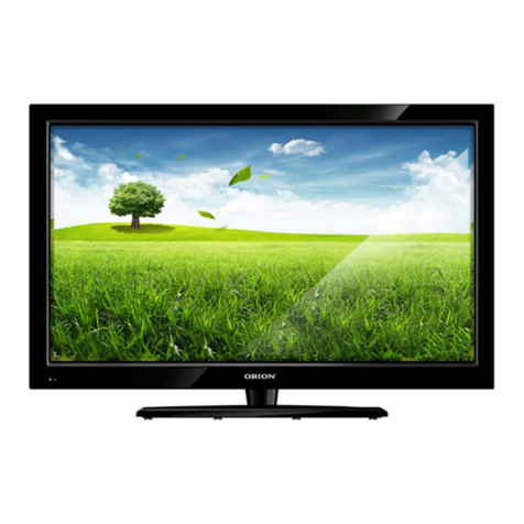
Orion LCD2028D User manual

]=
ORION
SERVICE MANUAL
LCD2028D

1.Complete Unit Circuit diagram
POWER
SWITCH
LCD P
A
NEL
C
ON
1
POWER BOARD
18V
C
ON
2
18V
18V
REMOTE BOARD
CN2
CN4
VIDEO
CN22
A
UDIO
CN11
SPEAKER
C
N3
ON
/
OFF
ADJ
KE
Y
BOARD
MAIN BOARD
DVD
_
IR
CN7
CN1
CN2
DVD
CD
R
O
/
-
DECODE BOARD
CN4
DVD
KE
Y
BOARD

2. Main Board
Power supply troubleshooting
Display troubleshooting
Audio troubleshooting
Functionare troubleshooting

If
F
1/3
A
with 12
V
?
N
Y
Check fuse FI or external power E33/470μF/16V if Voltage is5 V
N
Y
Fuse burnt when power on?
N
Y
N
Check if can power on
(via button or R/C)
Check power output
(U16,U18,U19)
OK Check F1 descending
Power supply network
Check if the second
Pin of U1 have 150
KHZ on-off signal
Y
LCD burnt out,
short-circuit
Y
OK
U1/
MP1410ES-LF
or
D17/IN5822 has problem
L9/47Μh circle inductance
or solder problem
No damage but voltage
is higher
U1/
MP1410ES-LF
the 4
th
pin
had Solder problem or U1
damaged
Check U21:
if
power supply
,
reset,vibration
works normally
N
No damage but
voltage is lower
E33: power leakage or short circuit of
descendin
g
p
ower
Y
1) Power problem

2
)
Dis
p
la
y
p
roblem(dis
p
la
y
distortion/Mosaic)
M
osa
i
c
Check if the cable connected to panel
is right and works normally
Y
N
Check if
panel is ok?
N
Y
Check if the out
p
ut of U5
cable socket is ok?
Y
N
Change
panel
Check the power supply
And timer circuit of U5
Change the cable
which drives the
panel
Replace or repair this
part of circuit

3
)
、
D
is
p
la
y
p
roblem
(white screen)
White screen
Check if Voltage for panel is
ok?( depend on the selected panel
)
N
Y
Y
Check G pole of Q24/AO34
01 has
the change of 3.3-0V or 5-0V
Y N YN
CN8 connecting defective
(provide have panel driving
voltage) or Q24 damaged
Check the circuit from the 98
th
pin of U21 to Q24
Panel defective or
drive cable for pane
has probleml
U5 defective or
power supply
abnormal
Check if U5 has signal output?

4
)
、
D
is
p
la
y
p
roblem
(black screen)
Black screen
Is there 5V backlight voltage
(
BLON
)
at CN19?
Y N
Check if inverter power supply
works nomally?
N
Y
Replace
Inverter
Check the circuit of Q26 or I/O
port of U21 (99
th
pin)
Check the
external power
supply

5
)
.Audio
p
roblem
(No sound)
N
o soun
d
Check if there is
Audio input
N
Is volume, MUTE
settings correct?
Y
Is there signal
output at CN11?
Check if voltage at the 7
th
pin of
U3/TPA1517NE is hi
g
her than 11
V
YN
N
Check if voltage at the 8
th
pin of U3 is higher or
equal
to
9.2V
Y
Check if the 1st and 9th pin
at U3 have input signal
N
Check if the 4TH and 6th pin
at U3 have output signal
N
Check if the 60th and 61th
pin
at
U3
have
output
signal
Y
Check
externa
l audio
device
R
eset
Check
external
speaker
Check the circuit
from the 104th
&105th pin of U21 to
the 8th pin of U3
Check is there audio imput
signal at U21:
PC: the 53rd & 54th pin
AV: the 49th& 50th pin
Scart:the 56th & 57th pin Check the
power
supply
circuit of
U3
U3
damaged
Check
U21:if
voltage
8V on 45th
pin is ok
or U21
damaged
Check
circuit
between
Audio
input jac
k
and U21
N
Y N
Y
Check
output
between U3
and CN23
N
N
Y
Y
Y
Check
the circuit
from the
60th &61th
pin of U21
to the 1st
A
nd 9th
pin of U3

6
)
Functionare (TV
Video)
TV
no channel scan/no video
N
Check if RF imput signal is ok?
Y
Check voltage at the 7
th
p
i
n
o
f T1/TEDE9-2B4A is 5V?
Y N
Y N
Y N
Y
N
Y N
Check
external
RF
device
Check th
e
circuit betwee
n
24
th
& 25
th
p
i
n
of U21 and 11
t
h
p
in
g
of T1
,
an
d
p
ower su
pp
l
y
o
f
U21
T1
damaged
Check/re
p
air
the
peripheral
circuit
Check I2C
circuit( connec
ted to the 108
th
& 109
th
pin of
U21 TDA15021H
Repair
R267/0
Ω
Check the
step-up
circuit of
the power
supply pin
Check the
power
supply
circuit of
the pin
Check voltage at the 9
th
pin o
f
T1 is 33V?
Check voltage at the 3
th
pin o
f T1 is 0V?
Check: is there I2C data at the 4
th
&5
th
pin o
f T1?
Check is there signal at the 11
th
of T1
?
Check voltage at the 1
st
pin o
f
T1 is 1.5-4.1V?
YN

7
)
.Functionare(TV
Audio)
TV
no sound,but have
video
Check if audio is ok under PC/AV
modes
N
Y
Check is there signal at the 2n
d
pin of
SAW2/AF389A2D
Refer to
“
No sound
”
checking process
1. SAW2
damaged
2. U21:
the
29
th
,30
th
pin have solder
problem
3. U21
p
ower su
pp
l
y
problem
4. U21
damaged
Check if the
circuit between
the 2
nd
pin of
SAW2
and
C133/0.01
μ
F
or
C133 is damaged
N
Y

8
)
.Functionare(PC)
PC
Mode
Check if R.G.B input signal
works well
Check if VS.HS signal is stable and
re
g
ular?
Y
N Y
N
Run auto-adjust
command
System
settin
g
s is
incorrect.
Reset
Check R.G.B
circuit
OSD
seetin
g
s
mismatch o
r
the in
p
ut
m
odel is
unsupported
Check VS.HS
circuit
Check VS.HS
circuit
Video not
centered Discolored Video
viabration No signal

9
)
、
F
unctionare(SCART、
A
V、S-
V
)
SCART RGB
、
SCART Video
、
S- Video
、
A
V
下
N
o si
g
nal
Discolored
N
o si
g
nal at all channels
except VGA
Check if R.G.B input signal of U5 is ok?
Y
N
Check power
supply of U21
Check VS.HS
circuit
System
settin
g
s is
incorrect.
Reset
Check R.G.B
circuit (Under
SCART R.G.B mode
,
check input
circuit)

3. DVD Decode Board
Operational Troubleshooting
Display Troubleshooting
Audio Troubleshooting
Disc Playing Troubleshooting

1
2 3 4
Powe
r
o
n
D
1. Initialize related registers (servo,DSP,RISC)
2. Move code related with RISC to SDRAM
3. Rese
t
RISC
D
Dis
p
l
a
y
LOGO
Does tra
y
close?
No
Close tra
y
C
Y
es
C
Does SLED
m
ove to inside?
No
Move to inside
Y
es
1. Judge if a disc has loade
d
2. Jump to related subroutine acc. to the
type of disc.
B
No
B
Do it receive a com
m
a
n
d
to o
p
en the tra
y
?
No
1.
K
ey scan or receive RC singnal
2. run the other subroutine
Y
es
1. Stop play disc, the open tray co
m
pletely
2. Dis
p
la
y
p
icture and info
r
m
ation of o
p
enin
g
A
No
Does it recevie the com
m
a
n
d
to tra
y
close?
Y
es
A
No O
p
eration
1
2 3
4

1
2 3 4
Powe
r
o
n
D
Voltages
in all pins of item PWR CON
aer no
r
m
a
l
No
1. Check cable
2. Check
p
ower block circuit
D
Y
es
Are 3V3 and 1V8 no
r
m
a
l?
No
Check LDO B1117-3V3 an
d
B1117-1V8 and
p
eri
p
heral circuit
Y
es
Dis
p
l
a
y
LOGO?
No
Is M
a
in Clock no
r
m
a
l?
No
Check oscillation circuit
C
C
Y
es
reset sin
g
al no
r
m
a
l?
No
Check reset circuit
Y
es
Is si
g
nal on FLASH no
r
m
a
l?
No
Check peripheral circuit
of FLASH
Y
es
B
Is si
g
nal on SDRAM no
r
m
a
l?
No
Check peripheral circuit
of SDRAM
B
Y
es
Y
es
Is input signal of TV
encoder no
r
m
a
l?
No
Check peripheral circuit
of TV Encode
r
Y
es
A
A
Is output signal of TV
encoder normal?
Y
es
No
Check peripheral circuit
of TV Encoder
A
Check the circuit of video filter, buffe
r
No Picture
1
2 3
4

1
2 3 4
A
D
D
If will the tray close
auto
m
atically whe
n
i
t
is open?
No
Signal TRAYOUT and
TRAYIN is correct?
No
Check the positio
n
-switc
h
i
n
LOADER
Y
es
Si
g
nal TRAY+ & TRAY- correct?
No
Check the circui
t
b
etwee
n
SPHE8281D and driver circuit
SS8050 SS8550 TO-92 foot
p
rin
t
Y
es
Y
es
Signal LOAD+ & LOAD- correct?
Y
es
No
Check
m
oto
r
drive
r
circui
t
SS8050 SS8550 TO-92 footprint
and
p
eri
p
heral
C
Check the circui
t
to
connec
t
LOADER
C
auto
m
aticall
y
whe
n
i
t
is i
n
outside? Signal DMEA on driver IC high level?
No
Check the circui
t
related wit
h
DME
A
Sled
g
e
m
ove to inside
No
Y
es
Y
es
Signal SCO is
m
ore tha
n
1.4V?
Y
es
No
Check the circui
t
related wit
h
SCO
B
N
o disc o
n
tra
y
Signal SL+ & SL- correct?
Y
es
No
Check Moto
r
Drive
r
BA5954FP
B
Check the coppe
r
trace o
r
cable
connec
t
to LOADER
A
Have the Loade
r
actio
n
to find disc?
Yes
B
No
Have FCO o
n
drive
r
IC a
n
y signal?
Yes
Signal FOC+ & FOC- correct?
Yes
Check the cable and circuit between Loader
and Moto
r
drive
r
(
BA5954
)
No
No
1. Check the signal fro
m
SPHE8281D
to Motor driver;
2. Maybe SPHE8281D is not work
Check peripheral circuit
of Motor driver
A
No DISC
1
2 3
4

1
2 3 4
B
D
W
h
e
n
read disc, Lase
r
ON OK?
No
Signal CDLDO and
DVDLDO is normal?
Y
es
No
Check the peripheral circui
t
of
SPHE8281D & two transistor
(
2SB1132
)
D
Y
es
Voltage of TP18 & TP21 OK?
Y
es
No
Check the peripheral circui
t
of
of two transisto
r
(
2SB1132
)
Check the circuit to connect loade
r
OP
U
m
a
y
b
eda
m
a
g
ed
Load a disc?
No
Lase
r
of
f
C
Y
es
C
Focus O
n
ok?
No
A
n
ysignalo
n
pins
A
BCDEF
of SPHE8281D
No
Check the circui
t
b
etwee
n
Loade
r
and SPHE8281D
Y
es
Signal FEO
(p
in34 of SPHE8281D
)
correct?
No
Check the peripheral circui
t
of SPHE8281D
Y
es
Y
es
Check the circui
t
fro
m
Pin32-34 of SPHE8281D
B
Disc ID correct?
No
Signal of Pin31(RFCT) of
SPHE8281D no
r
m
al?
No
Check Moto
r
Drive
r
BA5954FP
B
Y
es
Y
es
Check the circui
t
fro
m
Pin28-31 of SPHE8281D
S
p
indle o
n
OK?
No
SPDCO
(p
in47 of SPHE8281D
)
no
r
m
al?
No
Check SPHE8281D and its
p
eri
p
heral circui
t
A
Y
es
C
Y
es
Signal SP+ & SP- correct?
Yes
Check the connection between spindle
drive
r
and
(
BA5954
)
No
Check peripheral circui
t
of
(
BA5954FP
)
m
oto
r
drive
r
A
No DISC
1
2 3
4

1
C
2 3 4
D
Track o
n
OK?
No
Signal TEO
(p
in35 of SPHE8281D
)
no
r
m
al?
No
Check SPHE8281D and its
p
eri
p
heral circui
t
D
Y
es
Y
es
Signal TCO
(pin42 of SPHE8281D) normal?
Y
es
No
Check the TCO connectio
n
b
etwee
n
SPHE8281D
(p
in42 and
p
in36
)
Si
g
nal RAD+ & RAD- no
r
m
al?
No
Check SPHE8281D and its peripheral
circui
t
Y
es
Check the connectio
n
b
etwee
n
OP
U
and BA5954FP
C
C
Disc is read
y
?
No
Check RF si
g
nal
Y
es
Audio si
g
nal no
r
m
al?
No
Out
p
u
t
si
g
nal are correct?
No
Check audio DAC(SPHE8281D of
p
in164-167) and its peripheral
circui
t
Y
es
Y
es
Check the circui
t
of filte
r
A
m
p
lif
y
and
m
ute etc
B
B
IR and Ke
y
fucition?
No
TD6F MC
U
com
m
unicate wit
h
SPHE8281D OK?
No
Check connectio
n
b
etwee
n
SPHE8281D and TD6F(of CN19)
p
eri
p
heral circui
t
Y
es
Y
es
END Check the connectio
n
b
etwee
n
spindle
drive
r
and
(
BA5954
)
No Di
g
ital
A
udio out
A
A
1
2 3
4

.
Key
board
View of co
pp
er Side

DVD
Key
board
View of copper Side
Table of contents
Other Orion TV manuals

Orion
Orion Color CRT TV User manual

Orion
Orion LCD T22-DVDC User manual

Orion
Orion LED 3241 User manual

Orion
Orion TV1329 User manual

Orion
Orion LCD PIF26-D User manual

Orion
Orion 14MDM User manual

Orion
Orion 14ARX User manual

Orion
Orion TV20RN10D User manual

Orion
Orion MD17 User manual

Orion
Orion TV32LB2000(H) User manual