Orno OR-GB-449 User manual

OR-GB-449
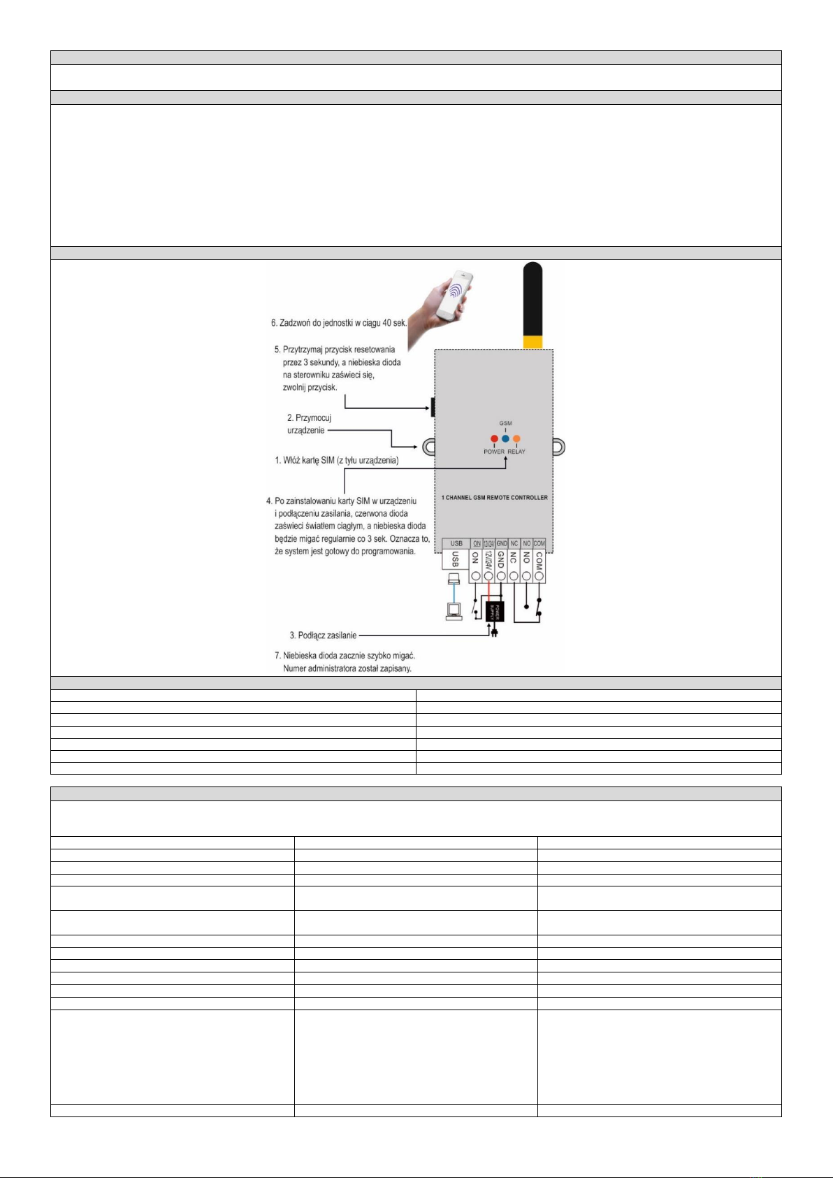
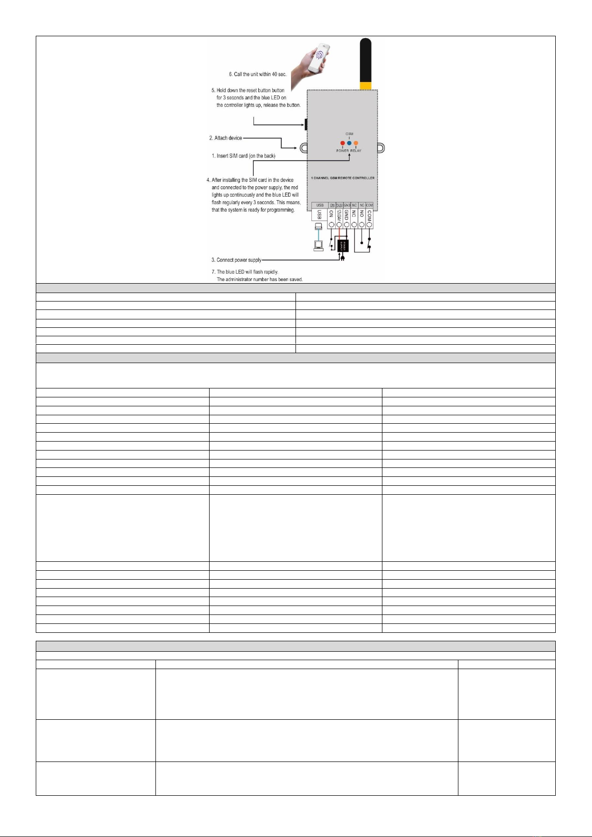
(PL) Kontroler GSM do sterowania bramą, z wejściem USB
(EN) GSM controller with USB input for automatic gate control
(DE) GSM-Controller mit USB-Eingang zur automatischen Gate-Steuerung
ORNO-LOGISTIC Sp. z o.o.
ul. Rolników 437
44-141 Gliwice POLAND
tel. (+48) 32 43 43 110
UWAGI DOTYCZĄCE BEZPIECZEŃSTWA/ SAFETY NOTES/ KOMMENTARE ZUR SICHERHEIT
WAŻNE!
Przed rozpoczęciem korzystania z urządzenia, należy zapoznać się z niniejszą instrukcją obsługi oraz zachować ją na przyszłość. Dokonanie samodzielnych napraw i modyfikacji skutkuje
utratą gwarancji. Producent nie odpowiada za uszkodzenia mogące wyniknąć z nieprawidłowego montażu czy eksploatacji urządzenia.
Z uwagi na fakt, że dane techniczne podlegają ciągłym modyfikacjom, Producent zastrzega sobie prawo do dokonywania zmian dotyczących charakterystyki wyrobu oraz wprowadzania
innych rozwiązań konstrukcyjnych niepogarszających parametrów i walorów użytkowych produktu.
Dodatkowe informacje na temat produktów marki ORNO dostępne są na: www.support.orno.pl. Orno-Logistic Sp. z o.o. nie ponosi odpowiedzialności za skutki wynikające
z nieprzestrzegania zaleceń niniejszej instrukcji. Firma Orno-Logistic Sp. z o.o. zastrzega sobie prawo do wprowadzania zmian w instrukcji - aktualna wersja do pobrania ze strony
www.support.orno.pl. Wszelkie prawa do tłumaczenia/interpretowania oraz prawa autorskie niniejszej instrukcji są zastrzeżone.
1. Nie używaj urządzenia niezgodnie z jego przeznaczeniem.
2. Wszelkie czynności wykonuj przy odłączonym zasilaniu.
3. Nie zanurzaj urządzenia w wodzie i innych płynach.
4. Nie obsługuj urządzenia gdy uszkodzona jest obudowa.
5. Urządzenie jest przeznaczone do użytku wewnętrznego.
6. Nie otwieraj urządzenia i nie dokonuj samodzielnych napraw.
7. Produkt przeznaczony do użytku w ramach maksymalnych wartości obciążenia.
IMPORTANT!
Before using the device, read this Operating Manual and keep it for future use. Any repair or modification carried out by yourselves results in loss of guarantee. The manufacturer is not
responsible for any damage that can result from improper device installation or operation.
In view of the fact that the technical data are subject to continuous modifications, the manufacturer reserves a right to make changes to the product characteristics and to introduce
different constructional solutions without deterioration of the product parameters or functional quality.
Additional information about ORNO products are available at www.support.orno.pl. Orno-Logistic Sp. z o.o. holds no responsibility for the results of non-compliance with the provisions
of the present Manual. Orno Logistic Sp. z o.o. reserves the right to make changes to the Manual - the latest version of the Manual can be downloaded from www.support.orno.pl. Any
translation/interpretation rights and copyright in relation to this Manual are reserved.
1. Do not use the device against its intended use.
2. Disconnect the power supply before any activities on the product.
3. Do not dip the device in water or another fluids.
4. Do not operate the device when its housing is damaged.
5. The device is designed to be operated inside buildings.
6. Do not open the device and do not repair it by yourselves.
7. The device is designed to operate with its maximum load ranges.
WICHTIG!
Vor der Inbetriebnahme des Geräts die Bedienungsanleitung sorgfältig lesen und für die zukünftige Inanspruchnahme bewahren. Selbständige Reparaturen und Modifikationen führen zum
Verlust der Garantie. Der Hersteller haftet nicht für die Schäden, die aus falscher Montage oder falschem Gebrauch des Geräts folgen können.
In Anbetracht der Tatsache, dass die technischen Daten ständig geändert werden, behält sich der Hersteller das Recht auf Änderungen in Bezug auf Charakteristik des Produktes und
Einführung anderer Konstruktionslösungen, die die Parameter und Gebrauchsfunktionen nicht beeinträchtigen, vor.
Zusätzliche Informationen zum Thema der Produkte der Marke ORNO finden Sie auf der Internetseite: www.support.orno.pl. Die Firma Orno-Logistic Sp. z o.o. haftet nicht für die Folgen
der Nichteinhaltung der Empfehlungen, die in dieser Bedienungsanleitung zu finden sind. Die Firma Orno-Logistic Sp. z o.o. behält sich das Recht auf Änderungen in der Bedienungsanleitung
vor –die aktuelle Version kann man von der Internetseite www.support.orno.pl herunterladen. Alle Rechte auf Übersetzung/Interpretation sowie Urheberrechte an dieser
Bedienungsanleitung sind vorbehalten.
1. Benutzen Sie das Gerät ausschließlich zu den in dieser Anweisung beschriebenen Zwecken
2. Alle Arbeiten dürfen nur bei abgeschalteter Stromversorgung durchgeführt werden.
3. Tauchen Sie das Gerät nicht ins Wasser oder in andere Flüssigkeiten.
4. Nutzen Sie die Anlage nicht, wenn ihre Gehäuse beschädigt ist.
5. Öffnen Sie die Einrichtung nicht und führen Sie keine selbstständigen Reparaturen aus.
6. Das Gerät eignet sich für den Gebrauch im Innen.
7. Das Produkt ist für Anwendung im Rahmen der maximalen Belastungswerte geeignet.
Każde gospodarstwo jest użytkownikiem sprzętu elektrycznego i elektronicznego, a co za tym idzie potencjalnym wytwórcą niebezpiecznego dla ludzi i środowiska odpadu, z tytułu obecności w sprzęcie niebezpiecznych substancji, mieszanin
oraz części składowych. Z drugiej strony zużyty sprzęt to cenny materiał, z którego możemy odzyskać surowce takie jak miedź, cyna, szkło, żalazo i inne. Symbol przekreślonego kosza na śmieci umieszczany na sprzęcie, opakowaniu lub
dokumentach do niego dołączonych wskazuje na konieczność selektywnego zbierania zużytego sprzętu elektrycznego i elektronicznego. Wyrobów tak oznaczonych, pod karą grzywny, nie można wyrzucać do zwykłych śmieci razem z innymi
odpadami. Oznakowanie oznacza jednocześnie, że sprzęt został wprowadzony do obrotu po dniu 13 sierpnia 2005r. Obowiązkiem użytkownika jest przekazanie zużytego sprzętu do wyznaczonego punktu zbiórki w celu właściwego jego
przetworzenia. Zużyty sprzęt może zostać również oddany do sprzedawcy, w przypadku zakupu nowego wyrobu w ilości nie większej niż nowy kupowany sprzęt tego samego rodzaju. Informacje o dostępnym systemie zbierania zużytego
sprzętu elektrycznego można znaleźć w punkcie informacyjnym sklepu oraz w urzędzie miasta/gminy. Odpowiednie postępowanie ze zużytym sprzętem zapobiega negatywnym konsekwencjom dla środowiska naturalnego i ludzkiego zdrowia!
Every household is a user of electrical and electronic equipment and therefore a potential producer of hazardous waste to humans and the environment from the presence of hazardous substances, mixtures and components in the equipment.
On the other hand, waste equipment is a valuable material, from which we can recover raw materials such as copper, tin, glass, iron and others. The symbol of a crossed-out rubbish bin placed on the equipment, packaging or documents
attached thereto indicates the necessity of separate collection of waste electrical and electronic equipment. Products marked in this way, under penalty of a fine, may not be disposed of in ordinary waste together with other waste. The
marking also means that the equipment was placed on the market after the 13th August 2005. It is the user’s responsibility to hand over the waste equipment to a designated collection point for proper treatment. Used equipment may also
be returned to the seller in case of purchase of a new product in a quantity not greater than the new purchased equipment of the same type. Information about the available waste electrical equipment collection
Jeder Haushalt ist ein Anwender von Elektro- und Elektronikgeräten und damit ein potenzieller Erzeuger von Abfällen, die für Mensch und Umwelt aufgrund des Vorhandenseins von gefährlichen Stoffen, Gemischen und Komponenten in den
Geräten gefährlich sind. Andererseits sind Altgeräte ein wertvoller Rohstoff, aus dem Rohstoffe wie Kupfer, Zinn, Glas, Eisen und andere zurückgewonnen werden können. Das Symbol der durchgestrichenen Mülltonne auf der Verpackung,
dem Gerät oder den dazugehörigen Dokumenten, weist auf die Notwendigkeit der getrennten Sammlung von Elektro- und Elektronikaltgeräten hin. Auf diese Weise gekennzeichnete Produkte dürfen unter Strafe nicht zusammen mit anderen
Abfällen entsorgt werden. Die Kennzeichnung weist gleichzeitig darauf hin, dass die Geräte nach dem 13 August 2005 in Verkehr gebracht wurden. Es liegt in der Verantwortung des Benutzers, die Altgeräte zur ordnungsgemäßen Behandlung
an eine dafür vorgesehene Sammelstelle zu bringen. Informationen über das verfügbare System zur Sammlung von Elektroaltgeräten finden Sie in der Informationsstelle des Ladens und im Magistrat/Gemeindeamt. Ein sachgemäßer Umgang
mit Altgeräten verhindert negative Folgen für die Umwelt und die menschliche Gesundheit!
05/2021

2
OPIS PRODUKTU
Urządzenie w prosty sposób pozwala na zdalną kontrolę wejścia, otwierania drzwi, bram wjazdowych, furtek, szlabanów lub innych urządzeń. Obsługa za pomocą wiadomości SMS lub
połączenia telefonicznego. Czteropasmowy moduł GSM. Dzięki wejściu USB urządzenie można również konfigurować za pomocą PC. Wyjście przekaźnikowe: 10A.
CHARAKTERYSTYKA PRODUKTU
- Obsługa do 1000 autoryzowanych użytkowników,
- Dodawanie użytkowników poprzez połączenie telefoniczne, SMS lub aplikację komputerową,
- Sterowanie automatycznymi bramami i szlabanami za pomocą SMS lub połączenia GSM (opłaty naliczane wg stawek operatora),
- Możliwość wyboru trybu sterowania, w zależności od rodzaju bramy,
- Możliwość sterowania różnymi bramami,
- Automatyczna konfiguracja sterowania czasowego,
- Programowanie i sprawdzanie statusu poprzez SMS,
- Wysyłanie powiadomień o otwarciu lub zamknięciu bramy lub szlabanu (do wyboru),
- Konfiguracja uprawnień użytkowników,
- Sterowanie może odbywać się tylko z autoryzowanych numerów telefonów skonfigurowanych w urządzeniu, lub z dowolnego numeru telefonu bez ograniczeń (w zależności od
ustawień),
- Regularne, automatyczne testy kontrolera.
MONTAŻ/INSTALACJA
DANE TECHNICZNE
Typ:
Kontroler GSM
Napięcie zasilania odbiornika:
12VDC
Maks. obciążenie:
2300W
Kolor:
Biały
Stopień ochrony:
IP20
Wymiary odbiornika:
76 x140x27mm
Inne cechy:
Programowanie za pomocą PC
SKRÓCONA INSTRUKCJA OBSŁUGI
Pierwszym krokiem jest dodanie numeru Administratora:
-podłącz zasilanie, naciśnij i przytrzymaj ok. 3 sec. przycisk RESET,
-gdy dioda GSM mruga zadzwoń na nr Karty Sim w sterowniku z telefonu Administratora
Funkcja
Komenda SMS
Informacja zwrotna
Zmiana hasła z 1234 na 1212.
1234CP1212
CP:1212
Ręczne dodanie numeru 111222333.
1212AD111222333#
SET OK.
Ręczne usunięcie numeru 111222333.
1212DD111222333#
DELETED.
Włączenie dodawania numerów poprzez połaczenie
głosowe.
1212ADD ON
ALLOW TO ADD USER NUMER
Wyłączenie dodawania numerów poprzez połaczenie
głosowe.
1212ADD OFF
DISABLE ADDING USER NUMER
Wykasowanie wszystkich numerów.
1212FD
FD OK
Dodanie numeru 222333444 z limitem 12.
1212LIMIT222333444*012#
SET OK.
Włączenie informacji zwrotnej dla Administratora.
1212SMS1#
SET OK.
Wyłączenie informacji zwrotnej dla Administratora.
1212SMS0#
SET OK.
Dostęp dla wszystkich numerów.
1212ATH0#
ANY CALLER ID
Dostęp dla zastrzeżonej listy numerów.
1212ATH1#
AUTHORIZATION MODE OK lub SET MODE OK
Kontrola statusu sterownika
CHK
RELAY1:OFF
RELAY2:OFF
MODE:A
PASSWORD:1212
FREE MEMORY:1022
AUTHORIZATION
CALLER ID
SIGNAL STRENGTH:21V
Wysterowanie wyjścia (można również zadzwonić).
ON1
(OUT1 ON)

3
Aktywacja trybu A- ustawienie czasu otwarcia 5 sek..
1212MA5#0
SET OK.
Wysterowanie wyjścia (można również zadzwonić).
ON1
(OUT1 ON)
Aktywacja trybu B z informacją zwrotną.
1212MB1#
SET MODE OK.
Aktywacja trybu B bez informacji zwrotnej.
1212MB0#
SET MODE OK.
Wysterowanie wyjścia.
ON1
(OUT1 ON)
Wysterowanie wyjścia.
OFF1
(OUT1 OFF)
Aktywacja trybu E- tryb Bistabilny
1212ME0#1
SET OK.
PEŁNA INSTRUKCJA OBSŁUGI URZĄDZENIA
1. Ustawienie numeru administratora
Funkcja
Komenda SMS
Informacja zwrotna
1.1 Ustawienie numeru
administratora poprzez połączenie
głosowe
-podłącz zasilanie, naciśnij i przytrzymaj ok. 3 sec. przycisk RESET,
-gdy niebieska dioda (GSM) zacznie migać zadzwoń na numer Karty Sim w sterowniku z
telefonu Administratora
- otrzymasz odpowiedź zwrotną, co będzie oznaczało poprawne ustawienie numeru
Administratora
- aby ponownie zmienić numer Administratora postępuj wg powyższych wskazówek,
- SAVE ADMIN OK
1.2 Ustawienie numeru
administratora poprzez wiadomość
tekstową SMS
Zakładając że numer Administratora to 666 555 444
- wyślij SMS o treści:
1234ADMIN666555444#
- otrzymasz odpowiedź zwrotną
- aby ponownie zmienić numer Administratora postępuj wg powyższych wskazówek
- SAVE ADMIN OK
1.3 Zmiana hasła
(domyślne ustawienie fabryczne
hasła to: 1234)
- aby zmienić hasło ustawione fabrycznie należy wysłać na numer Karty Sim w sterowniku SMS
o treści:
1234CP1212 (nowe hasło: 1212)
- otrzymasz odpowiedź zwrotną, co będzie oznaczało poprawną zmianę hasła na 1212
- CP: 1212
1.4 Dodawanie numerów poprzez
połączenie głosowe
- aby dodać nowe numery użytkowników należy wejść w tryb programowania wysyłając SMS
o treści:
1234ADD ON
- otrzymasz odpowiedź zwrotną,
- należy zadzwonić na numer Karty SIM w sterownika z telefonu, którego numer ID ma zostać
dodany. System automatycznie odrzuci połączenie,
- możliwe jest dodanie dowolnej liczby numerów ID użytkowników, aż do opuszczenia trybu
programowania.
- ALLOW TO ADD USER
NUMBER (zezwól na
dodanie numeru
użytkownika)
- ADD333222111 OK
(przyjmując, że numer
użytkownika to
333 222 111)
1.5 Wyłączenie dodawania numerów
poprzez połączenie głosowe
- aby wyłączyć tryb programowania/dodawania numerów ID użytkowników należy wysłać SMS
o treści:
1234ADD OFF
- otrzymasz odpowiedź zwrotną, co będzie oznaczało opuszczenie trybu dodawania numerów
ID użytkowników
- DISABLE ADDING USER
NUMBER (wyłączenie
dodawania numeru
użytkownika)
1.6 Dodawanie numerów poprzez
wiadomość tekstową SMS
- możliwe jest dodanie maksymalnie 8 numerów telefonów w jednej komendzie SMS, aby to
zrobić należy wysłać SMS o treści:
1234AD111111111#222222222#333333333#444444444#kolejne numery telefonów#
(gdzie liczby to kolejne numery telefonów, które chcemy dodać)
- otrzymasz odpowiedź zwrotną, co będzie oznaczało prawidłowe dodanie numerów telefonów
- SET OK
1.7 Usuwanie numerów poprzez
wiadomość tekstową SMS
- możliwe jest usunięcie maksymalnie 8 numerów telefonów w jednej komendzie SMS, aby to
zrobić należy wysłać SMS o treści:
1234DD111111111#222222222#333333333#444444444#kolejne numery telefonów#
(gdzie liczby to kolejne numery telefonów, które chcemy usunąć)
- otrzymasz odpowiedź zwrotną, co będzie oznaczało prawidłowe usunięcie numerów
telefonów
- DELETED
1.8 Usuwanie wszystkich numerów
poprzez wiadomość tekstową SMS
- możliwe jest usunięcie wszystkich numerów telefonów poprzez jedną komendę SMS, aby to
zrobić należy wysłać SMS o treści:
1234FD
- otrzymasz odpowiedź zwrotną, co będzie oznaczało usunięcie wszystkich numerów z listy
- FD OK
2. Ograniczenie dostępu dla
dowolnego numeru dzwoniącego
(można ustawić maksymalnie 250-
krotny dostęp dla danego numeru
telefonu)
- Administrator posiada możliwość ograniczenia dostępu dla dowolnego numeru dzwoniącego
Przykład:
Aby ograniczyć dostęp do systemu dla numeru 07847170001 tylko do 14 razy, należy wysłać
następującą komendę SMS:
1234LIMIT07847170001*014#
- system odsyła wiadomość zwrotną, co będzie oznaczało ustalenie 14-krotnego dostępu dla
danego numeru telefonu
- SET OK.
3. Włączenie/wyłączenie
informacji zwrotnej dla
Administratora
- Aby włączyć powiadomienia SMS dla Administratora należy wysłać SMS o treści:
1234SMS1#
- otrzymasz odpowiedź zwrotną.
- Aby wyłączyć powiadomienia SMS dla Administratora należy wysłać SMS o treści:
1234SMS0#
- otrzymasz odpowiedź zwrotną
- SET OK.
- SET OK.
4. Dostęp dla wszystkich numerów
telefonów
- Aby włączyć dostęp dla numerów telefonów skonfigurowanych w urządzeniu oraz dla
dowolnego numeru telefonu bez ograniczeń należy wysłać przez Administratora SMS o treści:
1234ATH0#
- otrzymasz odpowiedź zwrotną
- ANY CALLER ID
4.1 Dostęp dla zastrzeżonej listy
numerów telefonów
- Aby włączyć dostęp dla numerów telefonów skonfigurowanych w urządzeniu należy wysłać
przez Administratora SMS o treści:
1234ATH1#
- otrzymasz odpowiedź zwrotną
- AUTHORIZATION
CALLER ID
5. Ustawienie trybu pracy
5.1 Aktywacja trybu A - Programator
czasowy
- Tryb A jest funkcją fabryczną, umożliwia każdemu uprawnionemu rozmówcy wysterować
przekaźnik na określony czas, w zakresie od 1 sekundy do 65 000s
(podczas programowania tej funkcji można zadecydować o możliwości otrzymywania
powiadomień SMS lub o pominięciu tej możliwości)
Ustawienie fabryczne to:
Tryb A z czasem otwarcia przekaźnika 1 na 3 sekundy oraz wyłączonymi potwierdzeniami SMS.
Przykład:

4
1. Aby zaprogramować tryb A na czas otwarcia przekaźnika 1 na 60 sekund oraz włączyć możliwość
potwierdzenia SMS należy wysłać SMS o treści:
1234MA60#1
- system odeślę wiadomość zwrotną
2. Aby zaprogramować tryb A na czas otwarcia przekaźnika 1 na 1 sekundę oraz wyłączyć możliwość
potwierdzenia SMS należy wysłać SMS o treści:
1234MA1#0
- system odeślę wiadomość zwrotną
Uwaga: Po zakończeniu ustawiania trybu pracy można go kontrolować za pomocą darmowego
połączenia głosowego GSM lub poprzez wiadomość tekstową SMS:
- należy wysłać SMS o treści:
ON1
- system odeślę wiadomość zwrotną
- SET MODE OK.
- SET MODE OK.
- OFF1
5.2 Aktywacja trybu B - Praca
bistabilna Włącz/Wyłącz
- Tryb B umożliwia osobie dzwoniącej włączanie i wyłączanie przekaźnika 1 za pomocą
alternatywnych połączeń telefonicznych
(podczas programowania tej funkcji można zadecydować o możliwości otrzymywania
powiadomień SMS lub o pominięciu tej możliwości)
Przykład:
1. Aby zaprogramować tryb B i włączyć możliwość potwierdzenia SMS należy wysłać SMS o treści:
1234MB1#
- system odeślę wiadomość zwrotną, a osoba dzwoniąca otrzyma potwierdzenie SMS za
każdym razem, gdy przekaźnik 1 będzie włączany i wyłączany.
2. Aby zaprogramować tryb B i wyłączyć możliwość potwierdzenia SMS należy wysłać SMS o treści:
1234MB0#
- system odeślę wiadomość zwrotną.
Uwaga: Po zakończeniu ustawiania trybu pracy można go kontrolować za pomocą połączenia
głosowego GSM lub poprzez wiadomość tekstową SMS:
- należy wysłać SMS o treści:
ON1 (włącz) lub OFF1(wyłącz)
- system odeślę wiadomość zwrotną
- SET MODE OK.
- SET MODE OK.
- OUT1ON
- OUT1OFF
6. Aktywacja trybu E –
Programator czasowy
kombinowany
- Tryb E umożliwia sterowanie czasem otwarcia przekaźnika 1 poprzez krótkie kody SMS
Przykład:
1. Aby skonfigurować wstępnie ustawiony czas 3600 sekund dla przekaźnika 1 należy wysłać SMS o
treści:
1234ME3600#1
- system odeślę wiadomość zwrotną, a następnie aby aktywować przekaźnik 1 na 3600 sekund
należy wysłać krótki kod jako
ON1
- system odeślę wiadomość zwrotną, co będzie oznaczało otwarcie przekaźnika 1 na czas 3600
sekund
2. Aby wyłączyć otwarcie przekaźnika 1 w ciągu 3600 sekund należy wysłać SMS o treści:
OFF1
- system odeślę wiadomość zwrotną, a przekaźnik 1 zostanie wyłączony.
3. Aby ustawić przekaźnik 1 na stałe włączony i wyłączony należy ustawić czas na 0s. W tym celu
należy wysłać SMS o treści:
1234ME0#1
- system odeślę wiadomość zwrotną,
Aby włączyć przekaźnik 1 na stałe należy wysłać krótki kod SMS:
ON1
Aby wyłączyć przekaźnik 1 na stałe należy wysłać krótki kod SMS:
OFF1
- SET OK
- OUT1 ON
- OUT1 OFF
- SET OK
6.1 Aktywacja trybu F –Programator
czasowy responsywny
- Tryb F umożliwia natychmiastowe aktywowanie przekaźnika 1 i wyłączenie go po ustawionym
czasie (czas sterowania przekaźnikiem można ustawić w zakresie 1-65000sekund)
Przykład:
1. Aby aktywować przekaźnik 1 natychmiast i ustawić czas zatrzaskiwania na 3600 sekund należy
wysłać SMS o treści:
SC03600
- Przekaźnik 1 zostaje aktywowany natychmiast po otrzymaniu polecenia SMS, system odsyła
wiadomość zwrotną
- Po upłynięciu ustawionego czasu pracy przekaźnik 1 zostaje automatycznie wyłączony,
system odsyła wiadomość zwrotną
- OUT1 ON
- OUT 1 OFF
7. Ustawianie niestandardowych
powiadomień SMS
- System umożliwia wprowadzenie własnych, „niestandardowych” powiadomień SMS o
długości do 20 znaków
Przykład:
1. Aby ustawić niestandardowe powiadomienie dla przekaźnika 1, przychodzące podczas otwarcia
bramy o treści np. OTWARCIE BRAMY należy wysłać SMS o treści:
1234RL11:GATE OPEN
- system odsyła wiadomość zwrotną
2. Aby ustawić niestandardowe powiadomienie dla przekaźnika 1 po dezatywacji (zakładając, że
wiadomość SMS ma być GATE OPEN- brama otwarta) należy wysłać SMS o treści:
1234RL10:GATE OPEN
- system odsyła wiadomość zwrotną
3. Aby ustawić niestandardowe powiadomienie dla przekaźnika 1, przychodzące podczas zamknięcia
bramy o treści np. GATE CLOSING – brama zamknięta) należy wysłać SMS o treści:
1234RL11:GATE CLOSING
- system odsyła wiadomość zwrotną
4. Aby ustawić niestandardowe powiadomienie dla przekaźnika 1 po dezaktywacji (zakładając, że
wiadomość SMS ma być GATE CLOSING - brama zamknięta) należy wysłać SMS o treści:
1234RL10:GATE CLOSED
- system odsyła wiadomość zwrotną
- SMS CONTENT: GATE
OPENING
- SMS CONTENT : GATE
OPEN
- SMS CONTENT : GATE
CLOSING
- SMS CONTENT : GATE
CLOSED
8. Kontrola
- Aby upewnić się, że urządzenie pracuje prawidłowo Administrator może sprawdzać status
urządzenia poprzez otrzymywanie raportów w formie SMS (istnieje możliwość ustawienie
regularnych raportów w przedziale czasowym 0-65000 sekund).
Przykład:
1. Aby włączyć funkcję raportowania do Administratora w formie SMS po każdych 720 godzinach
należy wysłać SMS o treści:
TEST720
- system odsyła wiadomość zwrotną
Uwaga: Raport dotyczący przekaźnika 2 dotyczy 2 kanałowego sterownika.
- TEST OK, CTRL2-2G VER
RELAY 1:OFF
RELAY 2:OFF
MODE: A
PASSWORD: 1234
FREE MEMORY:1000
AUTHORIZED CALLER ID
SIGNAL STRENGTH:18

5
2. Aby wyłączyć funkcję raportowania należy wysłać SMS o treści:
TEST0
- system odsyła wiadomość zwrotną
Uwaga: Raport dotyczący przekaźnika 2 dotyczy 2 kanałowego sterownika.
- TEST OK, CTRL2-2G VER
RELAY 1:OFF
RELAY 2:OFF
MODE: A
PASSWORD: 1234
FREE MEMORY:1000
AUTHORIZED CALLER ID
SIGNAL STRENGTH:18
9. Kontrola statusu sterownika
- Administrator w każdym momencie może sprawdzić status systemu wysyłając SMS o treści:
CHK
- system odsyła wiadomość zwrotną
Uwaga: Raport dotyczący przekaźnika 2 dotyczy 2 kanałowego sterownika.
- RELAY 1:OFF
RELAY 2:OFF
MODE: A
PASSWORD: 1234
FREE MEMORY:1000
AUTHORIZED CALLER ID
SIGNAL STRENGTH: 18
10. Sprawdzanie wersji
oprogramowania
- Urządzenie aktualizuje się automatycznie. Aby sprawdzić aktualną wersję oprogramowania
należy wysłać SMS o treści:
TEST
- system odsyła wiadomość zwrotną.
Uwaga: Raport dotyczący przekaźnika 2 dotyczy 2 kanałowego sterownika.
- TEST OK, CTRL2-2G VER
RELAY 1:OFF
RELAY 2:OFF
MODE: A
PASSWORD: 1234
FREE MEMORY:1000
AUTHORIZED CALLER ID
SIGNAL STRENGTH:18
11. Resetowanie urządzenia do
ustawień fabrycznych
- Aby przywrócić ustawienia fabryczne urządzenia należy nacisnąć i przytrzymać przycisk
RESET przez ok. 10 sekund, niebieska dioda LED (GSM) będzie migać powoli, a następnie
szybciej. Zwolnij przycisk, RESET urządzenia do ustawień fabrycznych przebiegł pomyślnie.
1. Hasło administratora zostało przywrócone do domyślnego hasła 1234.
2. Tryby pracy zostały przywrócone do trybu A.
Uwaga: Jeżeli niebieska dioda LED (GSM) pozostaje włączona oznacza to, że resetowanie
urządzenia nie powiodło się. Należy ponownie nacisnąć przycisk RESET, aby wyjść z trybu
przywracania ustawień fabrycznych.
12. Aplikacja
12.1 Pobierz ze strony www.orno.pl aplikację GO2 i zainstaluj na komputerze.
12.2 Uruchom aplikację i podłącz przewodem USB kontroler do komputera.
12.3 Uruchom aplikację.
Strona 1
Naciśnij CONNECT aby nawiązać połączenie z kontrolerem.
Strona 2
Wyświetlony zostanie status kontrolera jak poniżej.
1. CONNECT/Disconnect: Kliknij, aby połączyć lub zakończyć połączenie, wartość siły sygnału sieci (zakres 1-26) można zobaczyć po udanej rejestracji sieci.
2. OUTPUT1/OUTPUT2: Aktywacja przekaźnika 1 i przekaźnika 2 (nie dotyczy), wybierz aby aktywować przekaźnik i odznacz aby dezaktywować przekaźnik.
3. Refresh: Wybierz ten przycisk, aby odświeżyć stronę.
4. Parametry:
<1> Administration password (hasło administratora): 4 cyfry (domyślnie 1234)

6
<2> Administrator SMS comfirmation (potwierdzenie SMS dla administratora): Po dokonaniu wyboru, administrator otrzyma wiadomość zwrotną po każdej operacji
<3> REGULARLY INSPECT (HOUR) –Regularna kontrola urządzenia: Funkcja ta służy do regularnego sprawdzania, czy urządzenie pracuje normalnie. Użytkownik
może ustawić, że po określonej godzinie sterownik automatycznie wyśle wiadomość testową na telefon komórkowy użytkownika, aby potwierdzić, że urządzenie
pracuje prawidłowo
<4> Authorized caller ID –autoryzowane numery telefonów: kontrola może być wykonywana tylko przez zaprogramowane numery w urządzeniu (domyślnie) lub
z dowolnego numeru telefonu bez ograniczeń (odznaczenie)
<5> Save: zapisz i wyślij nowe parametry do kontrolera
<6> Restore factory - przywrócenie ustawień fabrycznych: Numery, tryb pracy i hasło są przywracane do wartości fabrycznych.
<7>Firmware Build: Jun 27 2020 19:31:05 --- data ostatniej aktualizacji: 27 czerwca 2020 19:31:05
<8> Ready working - gotowy do pracy: Działa prawidłowo (working properly) –status kontrolera
Strona 3
1. Voice call - połączenie głosowe: połączenie użytkownika z kontrolerem.
2. Working mode (Tryb pracy): kontroler posiada cztery różne tryby pracy, możliwe do wyboru tryby sterowania w zależności od typu bramy
TRYB A: NON LOCK (Programator czasowy)
TRYB B: SELF LOCK (Praca bistabilna)
TRYB C: NON LOCK (dwa przekaźniki mogą pracować)
TRYB D: INTER LOCK (dwa przekaźniki mogą pracować)
Uwaga: TRYB C i TRYB D dotyczą 2-kanałowego sterownika GSM!
3. OUT 1 working time - czas pracy OUT1 (sek): funkcja domyślna i pozwala każdemu uprawnionemu rozmówcy na aktywację przekaźnika 1 od 1 sekundy do 65000.
4. OUT 2 working time - czas pracy OUT 2 (sek)- TRYB C pozwala zaprogramować zarówno przekaźnik 1 jak i przekaźnik 2 na niezależny okres od 1 sekundy do
65000s.
Dodatkowo możliwe jest zaprogramowanie opóźnienia czasowego od kiedy, przekaźnik 1 będzie aktywowany.
Dodatkowo możliwe jest zaprogramowanie opóźnienia czasowego od momentu zatrzaśnięcia przekaźnika 1 do aktywacji przekaźnika 2, czas opóźnienia to 1 sekunda
do 65 000 sekund, a jeśli nie ustawiono opóźnienia, przekaźnik 2 nie zostanie aktywowany (Uwaga: Nie dotyczy modelu OR-GB-449).
5. OUT1 SMS confirmation - potwierdzenie SMS OUT1 - można wybrać otrzymywanie lub nie otrzymywanie potwierdzenia SMS w czasie aktywacji i dezaktywacji
przekaźnika 1.
6. OUT2 SMS confirmation - potwierdzenie SMS OUT2 - można wybrać otrzymywanie lub nie otrzymywanie potwierdzenia SMS, gdy przekaźnik 2 jest włączony lub
wyłączony (Uwaga: Nie dotyczy modelu OR-GB-449).
Strona 4
1. SMS - użytkownik wysyła SMS do kontrolera.
2. OUT1 OFF/ON, OUT2 OFF/ON: Włączenie lub wyłączenie wiadomości niestandardowej, system pozwala na wprowadzenie do 20 znaków dla każdej indywidualnej
wiadomości.
3. OUTPUT 1/ OUTPUT 2 - WYJŚCIE 1 / WYJŚCIE 2 czas pracy (sek): Czas otwarcia dla przekaźnika 1 można ustawić w zakresie od 1-65000 sekund (opcjonalnie).
Uwaga: OUTPUT2- Wyjście 2 funkcja dotyczy 2 kanałowego modelu kontrolera GSM.

7
Strona 5
1. Add user number –dodawanie numerów użytkowników, możliwe jest dodanie maksymalnie 8 numerów użytkowników jednocześnie, aby zapisać wprowadzone
numery naciśnij przycisk <Save> zapisz.
2. User permission settings –ograniczenie dostępów dla użytkowników:
<1> wprowadź numer dla którego chcesz ustalić liczbę dostępów
<2> ustal liczbę dostępów dla danego numeru (zakres 0~250)
<3> Naciśnij <Save> –zapisz.
<4> Naciśnij <Query> w celu sprawdzenia ustawień.
3. Export all authorized numbers - wyeksportuj wszystkie autoryzowane numery: Naciśnij <List all>.
4. Delete all authorized numbers - usuń wszystkie autoryzowane numery: Naciśnij <Del all>.
5. Delete the specified number –usuwanie wybranych numerów użytkowników: wpisz numery, które chcesz usunąć, maksymalnie można wpisać 8 numerów
telefonów jednocześnie, następnie naciśnij <del> usuń.
6. Change administrator –zmiana administratora:
<1> Naciśnij <List all>, aby wyeksportować wszystkie numery
<2> 0 oznacza numer Administratora, usuń go wprowadzając wyświetlony numer i naciśnij <Del>. Następnie wprowadź nowy numer i naciśnij <Save>.
Strona 6
Strona 7
1. Restart –restart urządzenia.

8
2. Progress bar –pasek statusu postępu aktualizacji
3. Open firmware –wybierz folder plików aktualizacji
4. Upgrade –aktualizuj
Strona 8 –Tworzenie kopii zapasowej numerów użytkowników
1. Rozłącz kabel USB i połącz urządzenie ponownie.
2. Naciśnij <Backup all number to file> aby wykonać kopię zapasową wszystkich skonfigurowanych numerów z urządzenia do folderu.
3. Po zakończeniu procesu kopiowania numerów naciśnij <OK>.
4. Po zakończeniu tworzenia kopii zapasowej, odłącz kabel USB z kontrolerem.
5. Podłącz kabel USB z nowym kontrolerem i naciśnij <Connect>.
6. Naciśnij <Restore all number from file> aby otworzyć folder „my number”, kliknij ten plik i otwórz go. Gdy pasek postępu osiągnie 100% pojawi się okno powodzenia
przywracania numerów. Następnie naciśnij <OK> aby zakończyć import numerów na nowe urządzenie.
7. W celu wyświetlenia numerów użytkowników należy nacisnąć <List all> w zakładce Number.
Deklaracja zgodności
Orno-Logistic Sp. z o.o. oświadcza, że typ urządzenia radiowego: OR-GB-449, Kontroler GSM do sterowania bramą, z wejściem USB; jest zgodny z dyrektywą
2014/53/UE. Pełen tekst deklaracji zgodności UE jest dostępny pod następującym adres internetowym: www.support.orno.pl
EN
Operating instructions
DESCRIPTION
The device easily allows for remote control of the entrance, opening doors, entrance gates, wickets, barriers or other devices. Operation via SMS message or phone call. Four-band GSM
module. Thanks to the USB input, the device can also be configured via a PC. Relay output: 10A.
PRODUCT SPECIFICATION
- Support for up to 1000 authorised users,
- Add users by phone call, SMS or computer application,
- Control of automatic gates and barriers by SMS or GSM connection (fees charged according to the operator's rates),
- Selectable control modes, depending on the type of door,
- Possibility to control different gates,
- Automatic time control configuration,
- Programming and status check via SMS,
- Sending of notifications on the opening or closing of gates or barriers (optional),
- Configuration of user access rights,
- Control can be performed only from authorised phone numbers configured in the device, or from any phone number without restrictions (depending on settings),
- Regular, automatic tests of the controller.
INSTALLATION

9
TECHNICAL DATA
Type:
GSM controller
Receiver supply voltage:
12VDC
Max. load:
2300W
Color:
White
Ingress protection:
IP20
Receiver dimensions:
76 x140x27mm
Other features:
Programming via PC
QUICK START GUIDE
The first step is to add an Administrator number:
-Connect the power supply, press and hold the RESET button for approx. 3 sec,
-when the GSM diode blinks call the Sim card number in the controller from the Admin phone.
Function
SMS command
Feedback
Change password from 1234 to 1212.
1234CP1212
CP:1212
Manual addition of number 111222333.
1212AD111222333#
SET OK.
Manual deletion of number 111222333.
1212DD111222333#
DELETED.
Enable adding numbers by voice call.
1212ADD ON
ALLOW TO ADD USER NUMER
Disable adding numbers by voice call.
1212ADD OFF
DISABLE ADDING USER NUMER
Delete all numbers.
1212FD
FD OK
Addition of 222333444 with a limit of 12.
1212LIMIT222333444*012#
SET OK.
Enable feedback to the Administrator.
1212SMS1#
SET OK.
Disable feedback to the Administrator.
1212SMS0#
SET OK.
Access for all numbers.
1212ATH0#
ANY CALLER ID
Access for a restricted number list.
1212ATH1#
AUTHORIZATION MODE OK or SET MODE OK
Controller status monitoring.
CHK
RELAY1:OFF
RELAY2:OFF
MODE:A
PASSWORD:1212
FREE MEMORY:1022
AUTHORIZATION
CALLER ID
SIGNAL STRENGTH:21V
Output activation (can also be called).
ON1
(OUT1 ON)
Activation of A-mode - setting an opening time of 5 sec.
1212MA5#0
SET OK.
Output activation (can also be called).
ON1
(OUT1 ON)
Activation of B-mode with feedback.
1212MB1#
SET MODE OK.
Activation of B-mode without feedback.
1212MB0#
SET MODE OK.
Output setting.
ON1
(OUT1 ON)
Output setting.
OFF1
(OUT1 OFF)
Activation of E-mode (Bistable mode)
1212ME0#1
SET OK.
COMPLETE USER MANUAL
1. Setting the administrator number
Function
SMS command
Feedback
1.1 Setting the administrator number
by voice call
-connect the power supply, press and hold the RESET button for approx. 3 sec,
-when the blue (GSM) LED starts blinking call the Sim card number in the controller from the
Admin phone,
- you will receive a reply back, which means that you have set up your Administrator number
correctly
- to change the Administrator number again follow the above instructions.
- SAVE ADMIN OK
1.2 Setting the administrator number
by SMS
Assuming that the Administrator's number is 666 555 444
- send a text message:
1234ADMIN666555444#
- you will receive a reply back,
- to change the Administrator number again follow the above instructions.
- SAVE ADMIN OK
1.3 Password change
(factory default password: 1234)
- to change the factory-set password, send an SMS to the Sim card number in the controller:
1234CP1212 (new password: 1212)
- you will receive a reply back, which means that you have correctly changed your password to
1212
- CP: 1212

10
1.4 Adding numbers by voice call
- to add new user numbers, enter the programming mode by sending a text message:
1234ADD ON
- you will receive a reply back,
- call the SIM card number in the controller from the phone whose number you want to add.
The system will automatically reject the call,
- any number of users can be added until programming mode is exited.
- ALLOW TO ADD USER
NUMBER
- ADD333222111 OK
(assuming the user number
333 222 111)
1.5 Disable adding numbers by voice
call
- to deactivate the programming mode/addition of user numbers, send a text message:
1234ADD OFF
- you will receive a reply back, which means that you will leave the mode of adding user
numbers.
- DISABLE ADDING USER
NUMBER
1.6 Adding numbers by SMS text
message
- It is possible to add up to 8 phone numbers in one SMS command:
1234AD111111111#222222222#333333333#444444444#subsequent telephone numbers#
(where numbers are consecutive phone numbers that we want to add)
- you will receive a reply back, which means that the phone numbers have been added correctly
- SET OK
1.7 Deleting numbers by SMS text
message
- It is possible to delete up to 8 phone numbers in one SMS command:
1234DD111111111#222222222#333333333#444444444#subsequent telephone numbers#
(where numbers are consecutive phone numbers that we want to add)
- you will receive a reply back, which means that the phone numbers have been correctly
deleted
- DELETED
1.8 Deleting all numbers by SMS text
message
- It is possible to delete all phone numbers with one SMS command:
1234FD
- you will receive a reply back, which means that all numbers will be deleted from the list.
- FD OK
2. Limitation of access for any
caller number
(a maximum of 250 accesses per
phone number can be set)
- It is possible for the administrator to restrict access of any the caller id numbers up to 250
times
Example:
To restrict the number 07847170001 to access the system for only 14 times you would send the
following SMS command as:
1234LIMIT07847170001*014#
- the system sends a reply message, which means that 14 times access will be established for a
given telephone number
- SET OK.
3. Enable/disable feedback to the
Administrator
- to enable SMS alerts for the Administrator, send a text message:
1234SMS1#
- you will receive a reply back,
- to disable SMS alerts for the Administrator, send a text message:
1234SMS0#
- you will receive a reply back.
- SET OK.
- SET OK.
4. Access for all phone numbers
- To enable access for phone numbers configured in the device and for any phone number
without restrictions, send an SMS with the following content by the Administrator:
1234ATH0#
- you will receive a reply back.
- ANY CALLER ID
4.1 Access for a restricted list of
phone numbers
- To enable access for phone numbers configured in the device, send an SMS with the following
content by the Administrator:
1234ATH1#
- you will receive a reply back.
- AUTHORIZATION
CALLER ID
5. Working mode settings
5.1 Activation of A-mode - timer
- MODE A is the factory default function and allows any authorized caller to activate relay 1
from 1 second up to 65000.
(when programming this function, it is possible to decide whether or not to receive SMS
notifications)
The default setting is:
A-mode with the relay 1 latching time set at 3 seconds and the SMS confirmations are disabled.
Example:
1. To program mode A with the relay 1 latching time as 60 seconds and enable the SMS confirmation
function send an SMS command:
1234MA60#1
- the system will send you a reply message
2. To program mode A with the relay 1 latching time as 1 seconds and disable the SMS confirmation
function send an SMS command:
1234MA1#0
- the system will send you a reply message
Important: Once you have finished setting the mode, you can control it using GSM voice call
or via SMS text message:
- send an SMS command:
ON1
- the system will send you a reply message.
- SET MODE OK.
- SET MODE OK.
- OFF1
5.2 Activation of B-mode - Bistable
on/off operation
- MODE B allows the caller to activate relay 1 on/off with alternative telephone calls
(when programming this function, it is possible to decide whether or not to receive SMS
notifications)
Example:
1. To program MODE B and enable the SMS confirmation function send an SMS command:
1234MB1#
- the system will send a reply message and the caller will receive an SMS confirmation each
time relay 1 is switched on and off.
2. To program MODE B and disable the SMS confirmation function send an SMS command:
1234MB0#
- the system will send you a reply message
Important: Once you have finished setting the mode, you can control it using GSM voice call
or via SMS text message:
- send an SMS command:
ON1 lub OFF1
- the system will send you a reply message.
- SET MODE OK.
- SET MODE OK.
- OUT1ON
- OUT1OFF
6. Activation of E-mode –
Combined timer
- Mode E enables control of opening time of relay 1 by short SMS codes
Example:
1. To set up a timed preset latching time of 3600 seconds for relay 1 send an SMS command:
1234ME3600#1
- the system will send you a reply message, then to activate relay 1 for 3600 seconds you need
to send a short code as:
ON1
- the system will send a reply message, which means that relay 1 will be open for 3600 seconds
- SET OK
- OUT1 ON

11
2. To disable the opening of relay 1 within 3600 seconds, send an SMS command:
OFF1
- the system will send a reply message and relay 1 will be switched off.
3. To set relay 1 permanently on/off you need to set the time to 0s. To do this, send an SMS
command:
1234ME0#1
- the system will send a reply message,
To activate relay 1 permanently, send a short SMS code:
ON1
To disable relay 1 permanently, send a short SMS code:
OFF1
- OUT1 OFF
- SET OK
6.1 Activation of F-mode –
Responsive timer
- Mode F allows relay 1 to be activated immediately and deactivated after a preset time
(the relay control time can be set in the range of 1-65000 seconds)
Example:
1. To set the latch time of relay 1 for 3600 seconds and activate it immediately send an SMS
command:
SC03600
- Relay 1 is activated immediately after receiving SMS command, system sends back message
- After the set time has elapsed, relay 1 is automatically switched off, the system sends a reply
message
- OUT1 ON
- OUT 1 OFF
7. Setting custom SMS
notifications
- The system allows you to enter your own "non-standard" SMS notifications with a length of
up to 20 characters
Example:
1. To set up a custom notification for relay 1, coming during door opening with the content, e.g.
GATE OPEN, send an SMS command:
1234RL11:GATE OPEN
- the system will send a reply message,
2. To set up a custom notification for relay 1 after deactivation (assuming SMS message is GATE
OPEN) send an SMS command:
1234RL10:GATE OPEN
- the system will send a reply message,
3. To set up a custom notification for relay 1, coming when the gate is closed with the content e.g.
GATE CLOSING) send an SMS command:
1234RL11:GATE CLOSING
- the system will send a reply message,
4. To set up a custom notification for relay 1 after deactivation (assuming the SMS message is GATE
CLOSING) send an SMS command:
1234RL10:GATE CLOSED
- the system will send a reply message.
- SMS CONTENT: GATE
OPENING
- SMS CONTENT : GATE
OPEN
- SMS CONTENT : GATE
CLOSING
- SMS CONTENT : GATE
CLOSED
8. Regulary inspect
- To ensure that the device works properly, the administrator can check the status of the device
by receiving text messages.It can be set from 0-65000 seconds after regular SMS to the
administrator
Example:
1. To enable this function and set the device to send SMS messages after every 720 hours, send an
SMS command:
TEST720
- the system will send a reply message,
Note: The report for relay 2 is for a 2 channel controller.
2. To disable this function, send an SMS command:
TEST0
- the system will send a reply message,
Note: The report for relay 2 is for a 2 channel controller.
- TEST OK, CTRL2-2G VER
RELAY 1:OFF
RELAY 2:OFF
MODE: A
PASSWORD: 1234
FREE MEMORY:1000
AUTHORIZED CALLER ID
SIGNAL STRENGTH:18
- TEST OK, CTRL2-2G VER
RELAY 1:OFF
RELAY 2:OFF
MODE: A
PASSWORD: 1234
FREE MEMORY:1000
AUTHORIZED CALLER ID
SIGNAL STRENGTH:18
9. Checking the status
- The administrator can check the status of the system at any time by sending an SMS:
CHK
- the system will send a reply message,
Note: The report for relay 2 is for a 2 channel controller.
- RELAY 1:OFF
RELAY 2:OFF
MODE: A
PASSWORD: 1234
FREE MEMORY:1000
AUTHORIZED CALLER ID
SIGNAL STRENGTH: 18
10. Software version
- The device updates itself automatically. To check the current software version, send a text
message:
TEST
- the system will send a reply message,
Note: The report for relay 2 is for a 2 channel controller.
- TEST OK, CTRL2-2G VER
RELAY 1:OFF
RELAY 2:OFF
MODE: A
PASSWORD: 1234
FREE MEMORY:1000
AUTHORIZED CALLER ID
SIGNAL STRENGTH:18
11. Resetting the device to factory
settings
- To restore the device to factory settings, press and hold the RESET button for approximately
10 seconds, the blue LED (GSM) will flash slowly and then faster. Release the button, RESET of
the device to the factory settings has been successful.
1. The administrator password has been reset to the default password of 1234.
2. The operating modes have been reset to mode A.
Important: If the blue (GSM) LED remains on, it means that resetting the device has failed.
Press the RESET button again to exit factory reset mode.
12. Application
12.1 Download the GO2 application from www.orno.pl and install it on your computer.
12.2 Start the application and connect the controller to the computer with a USB cable.
12.3 Start the application.
Page 1
Click CONNECT to establish a connection with the controller.

12
Page 2
You will see the connection status as below.
1. CONNECT/Disconnect: Click to connect or exit the network connection, the network signal strength value (1-26) can be seen after the successful network
registration.
2. OUTPUT1/OUTPUT2: Activate relay 1 and relay 2 respectively, select to activate the relay and unselect to inactivate the relay
3. Refresh: Select this button to refresh the page
4. Parameters:
<1> Administration password: 4 digit (default 1234)
<2> Administrator SMS comfirmation: After the selection, the administrator will receive a confirmation message after each operation
<3> REGULARLY INSPECT (HOUR) –This function is used to check whether the device is working normally regularly. The user can set it after a limited hour, and the
controller will automatically send a test message to the user's mobile phone to confirm that the device is working normally
<4> Authorized caller ID –control can be performed only from authorized number in the device (default) or from any phone number without limitations(unselect)
<5> Save
<6> Restore factory - the number, working mode and password are all restored to factory default
<7> Firmware Build: Jun 27 2020 19:31:05 --- date of last update
<8> Ready working - Working properly
Page 3

13
1. Voice call - user call to control
2. Working mode: controller have four different working modes, selectable control modes depending on the type of the gate
A-mode: NON LOCK (Timer)
B-mode: SELF LOCK (Bistable operation)
C-mode: NON LOCK (two relays can work)
D-mode: INTER LOCK (two relays can work)
Important: MODE C and MODE D apply to the 2-channel GSM controller!
3. OUT 1 working time: the factory default function and allows any authorized caller to activate relay 1 from 1second up to 65000.
4. OUT 2 working time: MODE C allows you to program both relay 1 and relay 2 for an nonindependent period of 1second up to 65,000 seconds.
In addition it is possible to program a time delay from when, relay 1 latches and relay 2 isactivated. The time delay can be set from 1 second up to 65,000 seconds and
if there is no time delay set, then relay 2 will not activate.
(Note: Does not apply to model OR-GB-449).
5. OUT1 SMS confirmation - you can choose to receive or not receive SMS confirmations when relay is activated and deactivated.
6. OUT2 SMS confirmation - you can choose to receive or not receive SMS confirmations when relay is activated and deactivated.
(Note: Does not apply to model OR-GB-449).
Page 4
1. SMS - user send SMS to control
2. OUT1 OFF/ON, OUT2 OFF/ON: The system allows up to 20 characters for each customized message.
3. OUTPUT 1/ OUTPUT 2 - working time (SEC): Relay working time is 1-65000 seconds (optional)
Note: OUTPUT2- Output 2 function applies to the 2-channel GSM controller!
Page 5

14
1. Add user number –It is possible to add up to 8 telephone numbers at one time, and click <Save>. Press save to complete the Settings.
2. User permission settings:
<1> fill in the number to be restricted in the restricted number column
<2> fill in the number to be controlled in times (0 ~ 255)
<3> Click <Save>
<4> Click <Query> to check the Settings
3. Export all authorized numbers - Click <List all>.
4. Delete all authorized numbers –Click <Del all>.
5. Delete the specified number –fill in the numbers which you want to delete, up to 8 phone number at a time and click <del>.
6. Change administrator:
<1> Click <List all> to export all the numbers
<2> 0 represents the administrator number, and fill in the new administrator number to replace, and click <Save> to replace the administrator number.
Page 6
Page 7
1. Restart
2. Progress bar –Length update progress bar
3. Open firmware
4. Upgrade
Page 8 –Backup of user numbers

15
1. Disconnect the USB cable and reconnect the device.
2. Click <Backup all number to file> to backup all numbers of the old machine to the folder.
3. After the copying process is complete, click <OK>. The number will be automatically generated and saved in the folder.
4. After the backup is completed, unplug the old data cable
5. Insert the data cable into the USB socket of the new machine, and click <Connect> on the computer side to connect.
6. Click <Restore all number from file> to pop up the folder "my number", click this file and open it. When the progress bar is 100%, the restore success pop-up
window will pop up. Click <OK> to transfer the number successfully.
7. You can click <List all> in the number page to view the number.
Declaration of conformity
Orno-Logistic Sp. z o.o. declares that the type of radio device: OR-GB-449, GSM controller for gate control, with USB input; complies with Directive 2014/53/EU. The full
text of the EU declaration of conformity is available at the following internet address: www.support.orno.pl.
DE
Betriebsanleitung
BESCHREIBUNG
Das Gerät ermöglicht eine leichte Fernsteuerung (z.B. Öffnung) von Türen, Eingangstoren, Pforten, Schranken oder anderen Geräten und eine leichte Kontrole von Eingängen. Bedienung
per SMS-Nachricht oder Telefonanruf. Es hat einen Quad-Band-GSM-Modul. Dank des USB-Eingangs kann das Gerät auch über einen Computer konfiguriert werden. Relaisausgang:
10A.
PRODUKTMERKMALE
- Kann von bis zu 1000 autorisierte Benutzer bedient werden,
- Hinzufügung von Benutzern per Telefonanruf, SMS oder Computer,
- Die Steuerung von automatischen Toren und Schranken per SMS oder GSM-Verbindung (Gebühren werden nach den Tarifen des Mobilfunkanbieters berechnet),
- Wählbarer Steuermodus, abhängig von der Art des Tores,
- Möglichkeit der Ansteuerung verschiedener Toren,
- Automatische Konfiguration der Zeitsteuerung,
- Programmierung und Überprüfung des Status per SMS,
- Benachrichtigungen beim Öffnung oder Schließung eines Tores oder Schranke (optional),
- Konfiguration von Benutzerzugriffsrechten,
- Die Steuerung kann nur von autorisierten Telefonnummern, die im Gerät konfiguriert sind, oder von beliebigen Telefonnummern ohne Zugriffsrechteneinschränkungen (je nach
Einstellungen) erfolgen,
- Regelmäßige, automatische Tests des Controllers.
MONTAGE/INSTALLATION

16
DANE TECHNICZNE
Typ:
Controller GSM
Versorgungsspannung des Empfängers:
12VDC
Max. Belastung:
2300W
Farbe:
Weiß
Schutzklasse:
IP20
Abmessungen des Empfängers:
76 x140x27mm
Sonstige Merkmale:
Programmierung über Computer
KURZBEDIENUNGSANLEITUNG
Der erste Schritt ist ein Administratornummer hinzuzufügen:
-Stromversorgung einschalten, RESET-Taste ca. 3 Sek. gedrückt halten,
-Wenn die GSM-Diode blinkt, rufen Sie die Sim-Kartennummer im Controller vom den Admin-Telefon an
Funktion
SMS Befehl
Rückmeldung
Änderung des Passworts von 1234 auf 1212.
1234CP1212
CP:1212
Manuelles Hinzufügen des Nummers 111222333.
1212AD111222333#
SET OK.
Manuelles Löschen des Nummers 111222333.
1212DD111222333#
DELETED.
Aktivierung der Möglichkeit von Hinzufügung neuen
Nummern per Sprachanruf.
1212ADD ON
ALLOW TO ADD USER NUMER
Abschaltung der Möglichkeit von Hinzufügung neuen
Nummern per Sprachanruf.
1212ADD OFF
DISABLE ADDING USER NUMER
Alle Nummern löschen.
1212FD
FD OK
Hinzufügung des Nummers 222333444 mit
Begrenzung 12.
1212LIMIT222333444*012#
SET OK.
Aktivierung der Rückmeldung an den Administrator.
1212SMS1#
SET OK.
Abschaltung der Rückmeldung an den Administrator.
1212SMS0#
SET OK.
Zugriff für alle Rufnummern.
1212ATH0#
ANY CALLER ID
Zugriff für eingeschränkte Nummernliste.
1212ATH1#
AUTHORIZATION MODE OK oder SET MODE OK
Prüfung des Controller-Status.
CHK
RELAY1:OFF
RELAY2:OFF
MODE:A
PASSWORD:1212
FREE MEMORY:1022
AUTHORIZATION
CALLER ID
SIGNAL STRENGTH:21V
Ausgangsabschaltung (Man kann auch anrufen).
ON1
(OUT1 ON)
Aktivierung des Modus A - Einstellung der Öffnungszeit
5 Sek.
1212MA5#0
SET OK.
Ausgangsabschaltung (Man kann auch anrufen).
ON1
(OUT1 ON)
Aktivierung des Modus B mit Rückmeldung.
1212MB1#
SET MODE OK.
Aktivierung des Modus B ohne Rückmeldung.
1212MB0#
SET MODE OK.
Ausgangsabschaltung.
ON1
(OUT1 ON)
Ausgangsabschaltung.
OFF1
(OUT1 OFF)
Aktivierung des Modus E- Bistabiler Modus.
1212ME0#1
SET OK.
VOLLSTÄNDIGES BENUTZERHANDBUCH

17
1. Einstellen der AdministratornummerRückmeldung
Funktion
SMS Befehl
Rückmeldung
1.1 Einstellung der
Administratorennummer über einen
Sprachanruf
-Schließen Sie die Spannungsversorgung an, halten Sie die RESET-Taste ca. 3 Sekunden lang
gedrückt,
-wenn die blaue LED-Diode (GSM) fangt an zu blinken, rufen Sie die Sim-Kartennummer im
Controller vom Administratornummer an,
- wenn sie eine Rückmeldung erhalten, dann bedeutet es, dass die Administrator-Nummer
korrekt eingestellt wurde,
- Um die Administrator-Nummer erneut zu ändern, folgen Sie den Anweisungen oben,
- SAVE ADMIN OK
1.2 Einstellung der
Administratorennummer über einen
Sprachanruf per SMS
Angenommen, die Administrator-Nummer ist 666 555 444
- Senden Sie eine SMS mit folgendem Inhalt:
1234ADMIN666555444#
- Sie bekommen eine Rückmeldung
- Um die Administrator-Nummer erneut zu ändern, folgen Sie den Anweisungen oben.
- SAVE ADMIN OK
1.3 Änderung des Passwortes
(Die Werkseinstellungen des
Passwortes: 1234 )
- Um die werkseitige Voreinstellungen des Passwortes zu endern muss man eine SMS an die Sim-
Kartennummer im Controller mit folgendem Inhalt senden:
1234CP1212 (neues Passwort: 1212)
- wenn Sie eine Rückmeldung erhalten, dann bedeutet es, dass das Passwort korrekt auf 1212
geändert wurde.
- CP: 1212
1.4 Hinzufügung von neuen
Nummern per Sprachanruf
- Um neue Benutzer-ID-Nummern hinzuzufügen, müssen Sie den Programmiermodus aufrufen,
indem Sie eine SMS mit folgendem Inhalt senden:
1234ADD ON
- Sie erhalten eine Rückmeldung,
- rufen Sie die SIM-Kartennummer im Controller von dem Telefon an, dessen ID-Nummer Sie
hinzufügen möchten. Das System wird den Anruf automatisch abweisen,
- Man kann eine beliebige Anzahl von Benutzer-ID-Nummern hinzuzufügen, bis Sie den
Programmiermodus verlassen.
- ALLOW TO ADD USER
NUMBER (Erlaubnis der
Benutzernummer
hinzufügen)
- ADD333222111 OK
(Angenommen, die
Benutzernummer ist
333 222 111)
1.5 Aktivierung der Möglichkeit von
GlühbirneHinzufügung neuen
Nummern per Sprachanruf
- Um den Programmiermodus/das Hinzufügen von Benutzer-ID-Nummern zu deaktivieren,
müssen Sie eine SMS mit folgendem Inhalt senden:
1234ADD OFF
- wenn Sie eine Rückmeldung erhalten, dann bedeutet es, dass Sie den Programmiermodus (das
Hinzufügen von Benutzer-ID-Nummern) deaktiviert haben.
- DISABLE ADDING USER
NUMBER - Ausschalten des
Programmiermodus (des
Hinzufügens einer
Benutzernummer
1.6 Hinzufügung von neuen
Nummern per SMS
- Man kann bis zu 8 Rufnummern mit eine SMS-Nachricht hinzuzufügen, um es zu tun mussen
Sie eine SMS mit folgendem Inhalt senden:
1234AD111111111#222222222#333333333#444444444#subsequent telephone numbers#
(wobei die Nummern sind weitere Telefonnummern , die Sie hinzufügen möchten)
- wenn Sie eine Rückmeldung erhalten, dann bedeutet es, dass die Rufnummern korrekt
hinzugefügt wurden.
- SET OK
1.7 Nummern per SMS löschen
- Man kann bis zu 8 Rufnummern mit eine SMS-Nachricht löschen, um es zu tun mussen Sie
eine SMS mit folgendem Inhalt senden:
1234DD111111111#222222222#333333333#444444444#subsequent telephone numbers#
(wobei die Nummern sind weitere Telefonnummern , die Sie löschen möchten)
- wenn sie eine Rückmeldung erhalten, dann bedeutet es, dass die Rufnummern korrekt
gelöscht wurden
- DELETED
1.8 Alle Nummern per SMS löschen
- Man kann alle Rufnummern mit eine SMS-Nachricht löschen, um es zu tun mussen Sie eine
SMS mit folgendem Inhalt senden:
1234FD
- Wenn sie eine Rückmeldung erhalten, dann bedeutet es, dass die Rufnummern korrekt
gelöscht wurden
- FD OK
2. Zugriff für beliebige
Rufnummern einschränken (pro
Rufnummer können maximal 250
Zugänge eingestellt werden).
- Der Administrator hat die Möglichkeit, den Zugriff von jeden beliebigen Anrufernummer zu
beschränken
Beispiel:
Um den Zugriff auf das System für die Nummer 07847170001 auf nur 14 Zugange zu beschränken,
senden Sie eine SMS-Nachricht mit folgenden Befehl:
1234LIMIT07847170001*014#
- Wenn das System sendet eine Rückmeldung , dann bedeutet es, dass für die bestimmte
Telefonnummer wurde der 14-malige Zugang hergestellt
- SET OK.
3. Aktivieren/Deaktivieren der
Rückmeldung an den
Administrator
- Um SMS-Benachrichtigungen für den Administrator zu aktivieren, senden Sie eine SMS mit
dem folgenden Inhalt:
1234SMS1#
- Sie werden eine Rückmeldung bekommne,
- Um SMS-Benachrichtigungen für den Administrator zu deaktivieren, senden Sie eine SMS mit
dem folgenden Inhalt:
1234SMS0#
- Sie werden eine Rückmeldung bekommne
- SET OK.
- SET OK.
4. Zugriff für alle Rufnummern
- Um den Zugriff für im Gerät konfigurierte Telefonnummern und für beliebige
Telefonnummern ohne Einschränkungen zu ermöglichen, sollte der Administrator eine SMS mit
folgendem Inhalt senden:
1234ATH0#
- Sie werden eine Rückmeldung bekommne
- ANY CALLER ID
4.1 Zugriff für eingeschränkte
Nummernliste
- Um den Zugriff für die im Gerät konfigurierten Telefonnummern zu ermöglichen, sollte der
Administrator eine SMS mit folgendem Inhalt senden:
1234ATH1#
- Sie werden eine Rückmeldung bekommne
- AUTHORIZATION
CALLER ID
5. Einstellen des Arbeitsmodus
5.1 Aktivierung des Modus A-
Zeitschaltuhr
- Modus A ist eine werkseitig voreingestellte Funktion, die es jedem autorisierten Anrufer
ermöglicht, das Relais für eine bestimmte Zeitspanne zu setzen von 1 Sek. bis zu 65.000 Sek.
(bei der Programmierung dieser Funktion können Sie entscheiden, ob Sie eine SMS-
Benachrichtigungen erhalten möchten oder nicht)
Die Werkseinstellung ist:
Modus A mit einer Relaisöffnungszeit von 1 in 3 Sekunden und deaktivierten SMS-
Bestätigungen.
Beispiel:
1. Um den Modus A für 60 Sekunden zu programmieren und die SMS-Bestätigung zu aktivieren,
senden Sie eine SMS mit folgendem Inhalt:
1234MA60#1
- SET MODE OK.

18
- Das System wird Ihnen eine Rückmeldung senden
2. Um den Modus A so zu programmieren, so dass Relais 1 für 1 Sekunde geöffnet wird und die
Möglichkeit der SMS-Bestätigung deaktiviert wird, senden Sie eine SMS mit folgendem Inhalt:
1234MA1#0
- Das System wird Ihnen eine Rückmeldung senden
Achtung: Nachdem Sie die Einstellung des Arbeitsmodus abgeschlossen haben, können Sie ihn
mit einem kostenlosen GSM-Sprachanruf oder per SMS-Nachricht steuern:
- senden Sie eine SMS mit folgendem Inhalt:
ON1
- Das System wird Ihnen eine Rückmeldung senden
- SET MODE OK.
- OFF1
5.2 Aktivierung des Modus B -
Bistabilerarbeit (Ein/Aus-schalten)
- Im Modus B kann der Anrufer das Relais 1 über alternative Telefonate ein- und ausschalten
(bei der Programmierung dieser Funktion können Sie entscheiden, ob Sie SMS-
Benachrichtigungen erhalten möchten oder nicht)
Beispiel:
1. Um den Modus B zu programmieren und die SMS-Bestätigung zu aktivieren, senden Sie eine SMS-
Nachricht mit dem folgenden Inhalt:
1234MB1#
- das System wird eine Rückmeldung senden und der Anrufer erhält bei jedem Ein- und
Ausschalten von Relais 1 eine SMS-Bestätigung.
2. Um den Modus B zu programmieren und die SMS-Bestätigung zu deaktivieren, senden Sie eine
SMS-Nachricht mit dem folgenden Inhalt:
1234MB0#
- Das System wird Ihnen eine Rückmeldung senden
Achtung: Nachdem Sie die Einstellung des Arbeitsmodus abgeschlossen haben, können Sie ihn
mit einem kostenlosen GSM-Sprachanruf oder per SMS-Nachricht steuern:
- senden Sie eine SMS mit folgendem Inhalt:
ON1 lub OFF1
- Das System wird Ihnen eine Rückmeldung senden
- SET MODE OK.
- SET MODE OK.
- OUT1ON
- OUT1OFF
6. Aktivierung des Modus E –
Kombinierte Zeitschaltuhr
- Der E-Modus ermöglicht die Steuerung der Öffnungszeit von Relais 1 durch kurze SMS-Codes
Beispiel:
1. Um die vorläufig eingestellte Öffnungszeit von 3600 Sekunden für Relais 1 zu konfigurieren,
müssen Sie eine SMS-Nachricht mit folgendem Inhalt senden:
1234ME3600#1
- das System wird Ihnen eine Rückmeldung senden, dannach müssen Sie, um Relais 1 für 3600
Sekunden zu aktivieren, senden Sie diesen Kurzcode:
ON1
- Wenn das System eine Rückmeldung züruck schickt, dann bedeutet es Öffnung von Relais 1
für 3600 Sekunden
2. Um das Öffnen von Relais 1 innerhalb von 3600 Sekunden zu deaktivieren, müssen Sie eine SMS-
Nachricht mit folgendem Inhalt senden:
OFF1
- Das System wird Ihnen eine Rückmeldung senden, und das Relais 1 wird deaktiviert.
3. Um Relais 1 dauerhaft ein- und auszuschalten, müssen Sie die Zeit auf 0s einstellen. Um es zu tun
müssen Sie eine SMS mit folgendem Inhalt senden:
1234ME0#1
- Das System wird Ihnen eine Rückmeldung senden
Um Relais 1 dauerhaft anzuschalten, müssen Sie einen kurzen SMS-Code senden:
ON1
Um Relais 1 dauerhaft auszuschalten, müssen Sie einen kurzen SMS-Code senden:
OFF1
- SET OK
- OUT1 ON
- OUT1 OFF
- SET OK
6.1 Aktivierung des Modus F –
Reaktionsfähige Zeitschaltuhr
- Der F-Modus ermöglicht es, Relais 1 sofort zu aktivieren und nach der eingestellten Zeit zu
deaktivieren (die Relaissteuerungszeit kann im Bereich von 1-65000 Sekunden eingestellt
werden)
Beispiel:
1. Um Relais 1 sofort zu aktivieren und die Verriegelungszeit auf 3600 Sekunden einzustellen, senden
Sie eine SMS mit dem folgenden Inhalt:
SC03600
- Relais 1 wird sofort nach Empfang des SMS-Befehls aktiviert, das System wird Ihnen eine
Rückmeldung senden
- Nach Ablauf der eingestellten Zeit wird Relais 1 automatisch ausgeschaltet, das System wird
Ihnen eine Rückmeldung senden
- OUT1 ON
- OUT 1 OFF
7. Benutzerdefinierte SMS-
Benachrichtigungen einstellen
- Das System ermöglicht die Einführung eigener, "nicht standardisierter" SMS-
Benachrichtigungen mit einer Länge von bis zu 20 Zeichen
Beispiel:
1. Um die benutzerdefinierte Benachrichtigung für Relais 1 einzustellen, die bei der Tür öffnung
empfangen werden soll ( z. B. mit den Inhalt "TOR OFFEN"), senden Sie eine SMS- Nachricht mit
folgendem Inhalt:
1234RL11:GATE OPEN
- Das System wird Ihnen eine Rückmeldung senden
2. So stellen Sie eine benutzerdefinierte Benachrichtigung für Relais 1 nach der Deaktivierung ein
(unter der Annahme, dass die SMS-Nachricht "GATE OPEN"-(Tor öffen) lautet) senden Sie eine SMS-
Nachricht mit folgendem Inhalt:
1234RL10:GATE OPEN
- Das System wird Ihnen eine Rückmeldung senden
3. Um eine benutzerdefinierte Benachrichtigung für Relais 1 einzustellen, die beim Schließen des Tors
ankommt (z. B. "GATE CLOSING" -Tor schliessen) senden Sie eine SMS- Nachricht mit folgendem
Inhalt:
1234RL11:GATE CLOSING
- Das System wird Ihnen eine Rückmeldung senden
4. To set up a custom notification for relay 1 after deactivation (assuming the SMS message is GATE
CLOSING) send an SMS command:
1234RL10:GATE CLOSED
- Das System wird Ihnen eine Rückmeldung senden
- SMS CONTENT: GATE
OPENING
- SMS CONTENT : GATE
OPEN
- SMS CONTENT : GATE
CLOSING
- SMS CONTENT : GATE
CLOSED
8. Kontrolle
- Um sicherzustellen, dass das Gerät ordnungsgemäß funktioniert, kann der Administrator den
Status des Geräts überprüfen, indem er Berichte in Form von SMS-Nachrichten erhält (man
kann die Berichte so einstellen, dass sie regelmäßig in einem Zeitraum von 0-65000 Sekunden
ankommen).
Beispiel:
1. Um die Meldefunktion in Form von einer SMS nach jeweils 720 Stunden an den Administrator zu
aktivieren, senden Sie eine SMS-Nachricht mit folgendem Inhalt::
TEST720
- TEST OK, CTRL2-2G VER
RELAY 1:OFF
RELAY 2:OFF
MODE: A
PASSWORD: 1234
FREE MEMORY:1000
AUTHORIZED CALLER ID
SIGNAL STRENGTH:18

19
- Das System wird Ihnen eine Rückmeldung senden,
Achtung: Die Meldung für Relais 2 ist für einen 2-Kanal-Controller.
2. Um die Meldefunktion zu deaktivieren, senden Sie eine SMS mit folgendem Inhalt:
TEST0
- Das System wird Ihnen eine Rückmeldung senden
Achtung: Die Meldung für Relais 2 ist für einen 2-Kanal-Controller.
- TEST OK, CTRL2-2G VER
RELAY 1:OFF
RELAY 2:OFF
MODE: A
PASSWORD: 1234
FREE MEMORY:1000
AUTHORIZED CALLER ID
SIGNAL STRENGTH:18
9. Kontrolle des Controller-Status
- Der Administrator kann den Status des Systems in jederzeit durch einen SMS-Versand
überprüfen:
CHK
- Das System wird Ihnen eine Rückmeldung senden
Achtung: Die Meldung für Relais 2 ist für einen 2-Kanal-Controller.
- RELAY 1:OFF
RELAY 2:OFF
MODE: A
PASSWORD: 1234
FREE MEMORY:1000
AUTHORIZED CALLER ID
SIGNAL STRENGTH: 18
10. Prüfung der Software-Version
- Das Gerät aktualisiert sich automatisch. Um die aktuelle Softwareversion zu prüfen, senden
Sie eine SMS-Nachricht mit folgendem Inhalt:
TEST
- Das System wird Ihnen eine Rückmeldung senden
Achtung: Die Meldung für Relais 2 ist für einen 2-Kanal-Controller.
- TEST OK, CTRL2-2G VER
RELAY 1:OFF
RELAY 2:OFF
MODE: A
PASSWORD: 1234
FREE MEMORY:1000
AUTHORIZED CALLER ID
SIGNAL STRENGTH:18
11. Zurücksetzung des Geräts auf
Werkseinstellungen
- Um das Gerät auf die Werkseinstellungen zurückzusetzen, halten Sie die RESET-Taste für ca.
10 Sekunden gedrückt, die blaue LED (GSM) wird langsam und später schneller blinken. Lassen
Sie die Taste los, der RESET des Geräts auf die Werkseinstellungen war erfolgreich.
1. Das Administratorkennwort wurde auf das Standardpasswort von 1234 zurückgesetzt.
2. Die Arbeitsmodi wurden auf Modus A zurückgesetzt.
Achtung: Wenn die blaue LED-Diode (GSM) weiter leuchtet, dann bedeutet dies, dass der
Reset ist misslungen. Drücken Sie die RESET-Taste erneut, um den Werksreset-Modus zu
verlassen.
12. Applikation
12.1 Laden Sie die Applikation "GO2" von www.orno.pl herunter und installieren Sie sie auf Ihrem Computer.
12.2 Starten Sie die Applikation und schließen Sie mit dem USB-Kabel den Controller an dem Computer.
12.3 Starten Sie die Applikation.
Seite 1
Drücken Sie CONNECT, um eine Verbindung mit dem Controller herzustellen.
Seite 2
Der Controller-Status wird wie unten dargestellt angezeigt.
1. CONNECT/Disconnect: Klicken Sie darauf, um die Verbindung herzustellen oder zu beenden. Nach erfolgreicher Netzwerkregistrierung ist der Wert der
Netzwerksignalstärke (Bereich 1-26) zu sehen.
2. OUTPUT1/OUTPUT2: Aktivieren Sie Relais 1 und Relais 2 (betrifft nicht), wählen Sie es , um das Relais zu aktivieren und um das Relais zu deaktivieren heben Sie
die Auswahl auf.
3. Refresh: Wählen Sie diesen Knopf, um die Seite zu aktualisieren.

20
4. Parameter:
<1> Administration password: (Passwort des Administrators): 4 Ziffern (standardmäßig 1234)
<2> Administrator SMS comfirmation: (SMS-Bestätigung für Administrator): Nach der Auswahl erhält der Administrator nach jede Operation eine Rückmeldung
<3> REGULARLY INSPECT (HOUR) –Regelmäßige Geräteprüfung: Diese Funktion dient dazu, regelmäßig zu überprüfen, ob das Gerät normal arbeitet. Der Benutzer
kann den Controller so einstellen, dass er nach einer bestimmte Stunde automatisch eine Testnachricht an das Mobiltelefon des Benutzers sendet, um zu bestätigen,
dass das Gerät ordnungsgemäß funktioniert
<4> Authorized caller ID –autorisierte Telefonnummern: die Steuerung kann nur über die im Gerät programmierten Nummern erfolgen (standardmäßig) oder
von einer beliebigen Rufnummer ohne Einschränkungen (nicht markiert)
<5> Save: Speichern Sie und Senden neuer Parameter an den Controller
<6> Restore factory - werkseitige Voreinstellungen wiederherstellen: Nummern, Arbeitsmodus und Passwort werden auf die werkseitige Voreinstellungen
zurückgesetzt.
<7> Firmware Build: Jun 27 2020 19:31:05 --- Datum der letzten Aktualisierung: 27 Jun 2020 19:31:05
<8> Ready working - Betriebsbereit: Funktioniert einwandfrei (working properly) - Controller-Status
Seite 3
1. Voice call - Sprachverbindung: die Verbindung zwischen dem Benutzer und dem Controller.
2. Working mode: (Arbeitsmodus): Der Controller verfügt über vier verschiedene Arbeitsmodi, die Steuerungsmodi können je nach Art der Tür ausgewählt werden
TRYB A: NON LOCK (Zeitschaltuhr)
TRYB B: SELF LOCK ( Bistabilerarbeit)
TRYB C: NON LOCK (zwei Relais können arbeiten)
TRYB D: INTER LOCK (zwei Relais können arbeiten)
Achtung: Modus C i Modus D betreffen 2-Kanaligen GSM-Controller!
3. OUT 1 working time: Arbeitszeit OUT1 (sek): Die Standardfunktion, die es jedem autorisierten Anrufer ermöglicht die Relais 1 von 1 Sekunde bis 65000 zu
aktivieren.
4. OUT 2 working time: Arbeitszeit OUT 2 (sek)- Mit MODE C können Sie sowohl Relais 1 als auch Relais 2 für einen unabhängigen Zeitraum von 1 Sekunde bis
65000s programmieren.
Zusätzlich kann man eine Zeitverzögerung programmieren, ab der Relais 1 aktiviert werden soll.
Zusätzlich kann man eine Zeitverzögerung von der Aktivierung von Relais 1 bis zur Aktivierung von Relais 2 zu programmieren. Die Verzögerungszeit beträgt 1
Sekunde bis 65.000 Sekunden und wenn keine Verzögerung eingestellt wird, wird Relais 2 nicht aktiviert (Achtung: Es betrifft nich den OR-GB-449 Modell).
5. OUT1 SMS confirmation - OUT1 SMS-Bestätigung - Sie können wählen, ob Sie bei der Aktivierung und Deaktivierung von Relais 1 eine SMS-Bestätigung erhalten
sollen oder nicht.
6. OUT2 SMS confirmation - OUT2 SMS-Bestätigung- Sie können wählen, ob Sie bei der Aktivierung und Deaktivierung von Relais 2 eine SMS-Bestätigung erhalten
sollen oder nicht. (Achtung: Es betrifft nich den OR-GB-449 Modell).
Seite 4
1. SMS - der Benutzer sendet eine SMS an den Controller.
2. OUT1 OFF/ON, OUT2 OFF/ON: Aktivieren oder deaktivieren Sie die benutzerdefinierte Nachricht (das System erlaubt bis zu 20 Zeichen für jede einzelne
Nachricht)
3. OUTPUT 1/ OUTPUT 2 - Ausgang 1/Ausgang 2 Arbeitszeit (sec): Die Öffnungszeit für Relais 1 kann zwischen 1-65000 Sekunden eingestellt werden (optional).
Achtung: OUTPUT2- Die Funktion Ausgang 2 gilt für das 2-Kanal-Modell des GSM-Controllers.
Table of contents
Languages:
Other Orno Controllers manuals