Orolia MRO-50 User manual

Miniature, Ultra-Portable
High Precision & Performance
Atomic Frequency Source

Spectratime mRO-50Spectratime mRO-50
Contents
1. Introduction 3
2. mRO system description 3
2.1 Principle of operation and basic conguration 3
2.2 Physics Package (patent pending) 5
2.3 Electronics Package 5
2.3.1 Atomic resonance signal capture 5
2.3.2 Temperature controllers 6
2.3.3 C-eld 6
2.3.4 Telemetries 6
2.3.5 Frequency adjustment 7
3. The mRO-50 SPECIFICATIONS 7
4. mRO-50 installation and operation 7
4.1 Introduction 7
4.2 Safety! 8
4.3 Environmental Responsibility 8
4.4 Shipping and receiving information 8
4.5 Mounting 9
4.6 Pin Layout: 9
4.7 Normal operation 10
4.8 Serial interface operation 10
4.8.1 Introduction 10
4.8.2 Serial interface connection 10
4.8.3 mRO-50 parameters monitoring 11
4.8.4 Center frequency adjustment 14
4.9 Lock monitor 15

Spectratime mRO-50Spectratime mRO-50
1. Introduction
Spectratime used its 25 years of experience in manufacturing ultra-stable Rubidium oscillator for ground and space
applications to produce a miniaturized Rubidium Oscillator (mRO-50) with dimensions, packaging and pinout of crystal
oscillators (OCXO), measuring 50.8 mm x 50.8 mm x 19.5 mm. It delivers a square reference signal at 10 MHz (0 to 3.3 V)
with outstanding performances for a steady power consumption below 0.45 W at room temperature.
Such frequency references are well suited for applications demanding low power consumption, accuracy and retrace, high
frequency stability and low frequency drift such as telecom and mobile network synchronization (TDM, PTP), oil and gas
sensor-based exploration, navigation or timing instruments.
The mRO is described in this document divided into 4 chapters:
• A brief introduction
• A simple description of the principle of the clock
• The specications of the system
• The operation manual
2. mRO system description
2.1 Principle of operation and basic conguration
The mRO is a miniature rubidium clock and essentially consists of a voltage-controlled crystal oscillator (VCXO) which is
locked to a highly stable atomic transition in the ground state of the 85Rb isotope. While the frequency of the VCXO is at
the convenient standard frequency of 10 MHz, the rubidium clock frequency is at 3.036 GHz in the microwave range. The
microwave signal is directly generated with a second voltage-controlled oscillator (VCO). The phase-stable link between
the two oscillators is established with a fractional-N PLL (phase-locked loop).
The rubidium atoms are conned in a vapor cell at an elevated temperature. The cell is placed inside a cylinder with a gap
to which the microwave power derived from the VCO is coupled. The 85Rb atoms in the cell occur with equal probability
in the two hyperne energy levels of the ground state 5S (F=2 and F=3).
In order to detect the clock transition between these two levels, the atoms need to be manipulated in such a way that
most of them occur in only one level. This is done by optical pumping via a higher lying state (5P). Figure 1 shows the
atomic energy levels and transitions involved in the optical pumping process on the D1-line at 795 nm.
Figure 1: 85Rb optical pumping (D1 line) Figure 2: The C-eld (static magnetic eld) splits the Zeeman levels of
the 85Rb hyperne ground-state 5S. The clock transition between the
mF = 0 levels is only second-order sensitive to the applied magnetic eld.

Spectratime mRO-50Spectratime mRO-50
The pump light comes from a VCSEL (Vertical Cavity Surface Emitting Laser) which is tuned to resonance with the
transition between the ground-state F=3 level and the (un-resolved) excited states F’=2,3. The pump light excites 85Rb
atoms which are in the upper hyperne level (F=3) to the short-lived excited state 5P from which they decay to the two
ground state levels (F=2,3) with equal probability. Since pumping occurs continuously out of the F=3 level, a steady-state
is reached where most atoms are found in the F=2 level.
The level of the transmitted pump light is detected by a photodiode after the cell. When a microwave eld resonant
with the clock transition F=2*F=3 is coupled to the interaction region, the level F=3 is repopulated and light absorption
is enhanced. A sweep of the microwave eld over the resonance is detected as a small dip in the transmitted light level
after the cell.
This signal from the photodiode is fed into a synchronous detector whose output generates an error signal which corrects
the frequency of the crystal oscillator so that the (xed) phase-locked loop keeps the microwave VCO exactly on the
atomic resonance maximum.
The vapour cell is lled with metallic rubidium that contains both isotopes 85Rb (72%) and 87Rb (28%). In addition
the cell is lled with a buer gas which collides with rubidium atoms so as to keep them away from the cell walls and
restrict their movement. As a result the rubidium atoms are practically “frozen in place” for the interaction time with the
microwave eld. In this way the Doppler-eect is essentially removed and a narrow line width results.
The cell region is also surrounded by a pair of C-eld coils which generate a small axial static magnetic eld to resolve the
Zeeman sub-transitions of the hyperne line and select the clock transition, i.e. the one with the least magnetic sensitivity,
see Figure 2. To further reduce the magnetic sensitivity, the complete physics package is placed inside a magnetic shield.
Figure 3 gives a basic overview of the dierent functional blocks of the rubidium atomic clock. The rubidium clock consists
of two dierent packages. First, the Physics Package noted PP, which includes the VCSEL, the rubidium vapor cell, the
cylinder coupling the microwave to the rubidium atoms, two C-eld coils and an optical lter. Second, the Electronics
Package noted EP, which includes the microwave generation, the detection circuitry, temperature controllers, monitoring
and signal processing.
Figure 3: miniaturized
Rubidium atomic clock
principal block diagram

Spectratime mRO-50
2.2 Physics Package (patent pending)
The main design characteristics of the PP are its low power consumption, small size and mass, along with minimal
environmental sensitivities and mechanical ruggedness.
All parts of the PP are incorporated into a DIL-14 package hermetically sealed o under Xenon atmosphere to reduce
temperature exchange by convection and minimize electrical power consumption.
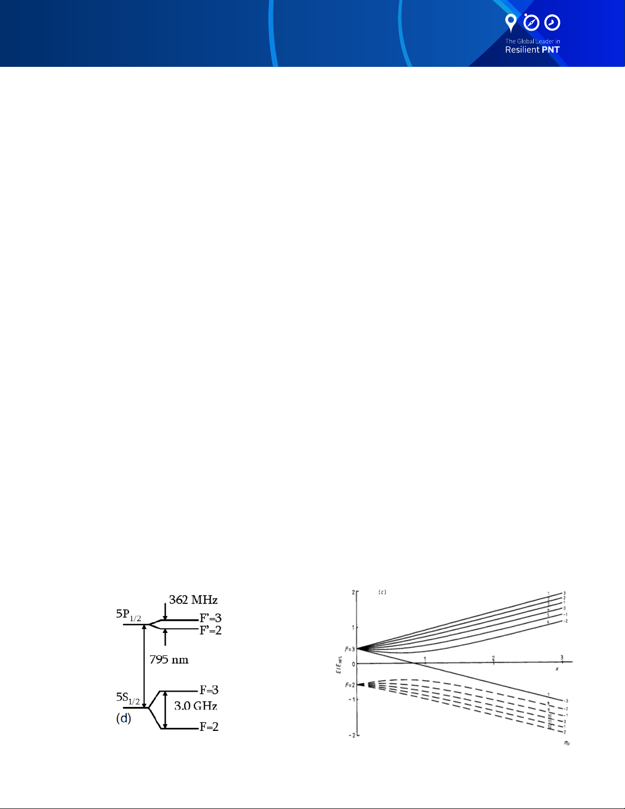
The light source selected for its compactness and low power consumption is a Vertical Cavity Surface Emitting Laser
(VCSEL) at 795 nm. It is coupled to a glass blown cell lled with Rubidium and buer gas surrounded by a cavity coupled
to the microwave signal.
The cavity has two purposes: 1) couple the Rubidium atoms to the microwave eld as mentioned previously but also 2)
transfer the heat to the cell and make a thermally stable environment around the glass cell as an oven. Both components,
VCSEL and Cell, are temperature stabilized.
The design is completed with Helmholtz coils, an optical lter and the photodetector.
2.3 Electronics Package
2.3.1 Atomic resonance signal capture
The mRO transition is a microwave transition at 3.036 GHz.
The microwave resonance which occurs as a dip in the optical signal after transiting the cell, is detected by a photodiode.
The basic purpose of the EP is to synchronize the entering microwave frequency, derived from a temperature compensated
crystal oscillator (TCXO), to this absorption dip. It is achieved by tuning the microwave frequency to maximum optical
absorption.
Frequency variations of the microwave signal are transformed into DC current changes at the photodetector. The dip,
visualized in the photocurrent versus microwave frequency curve of Figure 4 is very small: on the order of 1% of the total
photocurrent.
Since DC detection of the dip is not feasible, an AC detection method is used for the following reasons:
• The dip amplitude is very small compared to the total photocurrent.
• The slope of the derivative of the dip photocurrent versus microwave frequency corresponds to roughly 100 pA/
Hz. AC detection is the only solution to have a good signal/noise ratio since the photo-detector with associated
amplier are aected by icker noise.
The AC method involves square wave frequency modulation of the microwave signal at a rate of approximately 105
Hz. As shown in Figure 4, the modulated microwave frequency ips between 2 discrete frequency values f1 and f2. The
resulting photo-current i(t) appears also (after the transient) at 2 discrete values i1 and i2. The dierence between i1
and i2 produces the error signal used to adjust the crystal oscillator center frequency until the mean value of f1 and f2 is
exactly equal to the rubidium hyperne frequency.

Spectratime mRO-50
2.3.2 Temperature controllers
Since the temperature of the VCSEL and the Cell must be adjusted independently, two separated heaters are necessary
to control the temperature of the PP main parts. The temperatures are controlled by compensating thermal losses using
heating elements (no cooling). Temperature regulation servo-loops are based on a temperature sensor (NTC within a
Wheatstone bridge), Proportional-Integral (PI) regulator and a heating element.
2.3.3 C-eld
A pair of C-eld coils inside the PP generate a magnetic eld which separates the rubidium spectral lines. This magnetic
eld allows ne-tuning of the output frequency by shifting the rubidium resonance frequency by the second-order
Zeeman eect.
A stabilized current drives the coils. The current is adjustable for ne-tuning of the output frequency and can be set by a
software interface or by an analog voltage applied to the mRO pin #1.
2.3.4 Telemetries
The user can access these data from a software GUI shown in Figure 5. Telemetry parameters shown include:
• Error signal of the atomic lock loop
• DC signal on photodiode
• VCSEL temperature
• Control signal of the VCSEL temperature controller
• Cell temperature
• Control signal of the Cell temperature controller
• EP temperature
• VCSEL driving current
• Voltage across the VCSEL
• Control voltage of the 10 MHz crystal
Figure 4: Atomic resonance:
error signal detection

Spectratime mRO-50
More details are given in 4.8.3.
More specic information on the Spectratime mRO-50 - Evaluation Kit document
2.3.5 Frequency adjustment
The C-eld coil within the PP provides ne frequency adjustment capabilities. The value of the output frequency is
settable by applying an analog voltage to pin #1 (see 4.8.4) or by software by step of 0.04 ppb (part per billion, i.e. 10-9).
The microwave frequency at 3.036 GHz can be set in steps of 4.8 Hz by software (see 4.8.4). The corresponding fractional
resolution is 1.6 ppb.
3. The mRO-50 SPECIFICATIONS
The specications of this product are available on our website www.spectratime.com.
4. mRO-50 installation and operation
4.1 Introduction
This chapter of the manual contains information regarding the installation and operation of the mRO-50. It is recommended
to read this chapter carefully prior to operate the unit.
Figure 5: Control and monitoring software for the mRO-50

Spectratime mRO-50
4.2 Safety!
• The equipment contains small quantities of rubidium metal hermetically sealed inside the glass lamp and cell
assemblies, hence, any dangers arising from ionizing radiation are caused for human health (exemption set in
article 3 to Council directive 96/29/Euratom).
• For further information, ask for the «rubidium product data sheet».
• Handling the product in a reasonably foreseeable conditions do not cause any risk for human health, exposure to
the SVHC (substances of very high concern) would require grinding the component up.
4.3 Environmental Responsibility
• The equipment contains materials, which can be either re-used or recycled.
• Do not deposit the equipment as unsorted municipal waste. Leave it at an authorized local WEEE collection point
or return to Orolia Switzerland SA to ensure proper disposal.
• To return the appliance:
• Download and ll up the RMA form (from www.spectratime.com) and send it to WEEE@spectratime.com
• Once the RMA is approved, we will contact you with shipment process details.
4.4 Shipping and receiving information
The mRO-50 is packaged and shipped in a foam-lined box. The unit is inspected mechanically and electrically prior to
shipment. Upon receipt of the unit, a thorough inspection should be made to ensure that no damage has occurred during
shipping. If any damage is discovered, please contact
OROLIA SWITZERLAND SA
PHONE: +41 32 732 16 66
FAX: +41 32 732 16 67
CH-2000 NEUCHATEL / SWITZERLAND
Should it be necessary to ship the unit back, the original case and packing should be used. If the original case is not
available, a suitable container with foam-packing is recommended.
CAUTION
Care must be taken for the transportation of the mRO-50 to ensure that the maximum acceleration due to a shocks
50g/11ms is not exceeded.
mRO-50 contains glass bulbs, crystal resonators.
When mRO-50 integrated into an instrument, such instrument shall be packed in a suitable container, similar to
containers generally use for the transportation of instruments like scope, video display or computer.
- Use proper ESD precautions - Ensure that all cables are
properly connected

Spectratime mRO-50
4.5 Mounting
CAUTION
Care must be taken to ensure that the maximum operating temperature is not exceeded, (+60°C (+65°C if option E)
as measured at the unit’s base plate)
This maximum temperature can be reached when operating the unit into forced air ow at 60°C (65°C).
The mRO-50 is a well shielded unit, using several magnetic shield. Nevertheless, some consideration must be given to the
operating location of the unit, regardless of its application. To minimize frequency osets and/or non-harmonic distortion,
the unit should not be installed near equipment generating strong magnetic elds such as generators, transformers, etc…
The general information for the mechanical interface of the mRO-50 unit is given in the package drawing Figure 6 (all
dimensions in mm).
*
*
*4.6 Pin Layout:
PIN FUNCTION
1 Frequency Adjust (Analog 0-3V)
2 GND
3 10MHz square output (0-3V)
4 GND
5 Power 5V or 3.3V depending on model
6 /LOCK (Bit)
7 TxD
8 RxD
9 NC
10 NC
*± 0.4 mm
All other quotes are ± 0.2 mm

Spectratime mRO-50
4.7 Normal operation
When 5 or 3.3 Vdc, depending on the option, is applied to pin #5 (+), the unit will immediately generate a 10 MHz signal
from the crystal oscillator. Within approximately 70 seconds after application of input power, the unit will “lock”, i.e. the
crystal is now synchronised by the atomic resonant frequency.
The unit is able to provide a single signal called ‘/lock monitor’ (pin #6) which toggles from high to low level when the
internal crystal oscillator is locked to the Rb atomic resonance (see 4.9). The center frequency is tunable by applying
an ultra-stable analog voltage to pin #1. It is also possible to adjust the frequency by software (cf. iSource_mRO-50_
EvalBoard_Manual.pdf or see 4.8.4).
4.8 Serial interface operation
4.8.1 Introduction
The mRO-50 integrates a micro-controller with A/D and D/A embedded converters. The micro-controller is used to set
the parameters of the clock but also to lock the TCXO on the Rb absorption ‘dip’.
The built-in serial interface allows an automatic parameter adjustment during the manufacturing process as well as a ne
and coarse adjustment of the center frequency. All the working parameters are stored in a built-in EEPROM memory and
are accessible through the serial interface for monitoring.
The user must send commands with the following pattern (TxD):
command | carriage return to validate command
Example: monitor1<CR> or MON_tpcb PIL_celd 0F60<CR>
Remark: the system removes the line feeds and spaces and is case insensitive.
The returned response is decomposed as following (RxD):
response (if there is) + carriage return + line feed
Example: 0123<CRLF>
or error response (if there is) + “ ?” + 8 bits number corresponding to the error type + carriage return + line feed
Example: 0123 ?08<CRLF>
4.8.2 Serial interface connection
The data transfer from the mRO-50 is made by direct connection to a PC or standard terminal.
The data transfer parameters are the following:
• bit rate: 9600 bits/s
• parity: none
• start bit: 1
• data bits: 8
• stop bit: 1
IMPORTANT NOTE
In most cases, the serial PC interface accepts the 0 to 3.3V level and a direct connection can be made.

Spectratime mRO-50
4.8.3 mRO-50 parameters monitoring
The parameters monitoring is readable through the serial interface and with the use of the single command ‘MONITOR1‘
followed by a carriage return character. The mRO-50 will respond to this command with an ASCII/HEX coded string as
shown below.
AAAABBBBCCCCDDDDEEEEFFFFGGGGHHHHIIIIJJJJKKKKLLLLMMMMNNNNOOOO<CRLF>
(example: 08F90BCE10CC0F8C09600BFC07E207E507C00B5F0D970D1B09D709554D05<CRLF>)
This string is composed of the 15 parameters. The DEC(X) function is the conversion of the hexadecimal to decimal value.
Each returned byte is an ASCII coded hexadecimal value. The value are coded full range (4800: 0x0000 to 0x12C0 and
4095: 0x0000 to 0x0FFF) but are truncated into the software of the mRO.
• (AAAA) Rubidium cell temperature setpoint: during the optimization of the clock, the temperature of the glass
cell is adjusted to maximize the ratio absorption and power consumption. The temperature at this maximum is
dene as setpoint.
The highest hexadecimal value is 0x0BB8 which corresponds to 101°C.
• (BBBB) LASER temperature setpoint: the temperature of the VCSEL is set to match the laser wavelength to
the Rubidium resonance for a xed driving current. The temperature determined during this process is xed as
setpoint.
The highest hexadecimal value is 0x0E49 which corresponds to 100°C.
• (CCCC) LASER current setpoint during start-up: after switch-on, the mRO-50 runs the process of locking the
light source to the Rubidium resonance which lasts 70 seconds. During this process, the current driving the VCSEL
is xed to a high value. The light control loop is closed and the current will converge to the value which enables the
lock.
The maximum driving current is 1.8 mAmp (0x1130).
• (DDDD) C-eld current setpoint: a small current crosses the pair of C-eld coils which generate a small axial
static magnetic eld to resolve the Zeeman sub-transitions of the hyperne line and select the clock transition.
The maximum current of the C-eld is 5882 μAmp (0x0000).
R
NTC
( Ohm) =
1−X
10 000 ×
X
with
X
= 1 −
DEC(AAAA)
4800
T (°C) =
RNTC( Ohm) = 1−X
20 000 × X
4100 × 298.15
298.15 ×
ln(
10
-
5
×RNTC)
+ 4100 −273.14
DEC(BBBB)
4800
with X= 1 −
T(°C) =
I(mAmp)= ×
4100 × 298.15
298.15 × ln(10-5×RNTC)+ 4100 −273.15
1000
3 × DEC(CCCC)
4800 3 × 510
I(μAmp) = × 106
510
3 × (4800 −DEC(DDDD))
4800
V(Volt)=3 × DEC(EEEE)
4800
V(Volt)=3 × DECsigned(FFFF)
4095
V(Volt)=3 × DEC(GGGG)
4095
V(Volt)=3 × DEC(GGGG)
4095
I(nA)= 1.5 −3 × DEC(IIII)
4095 × 100
V(Volt)=3 × DEC(GGGG)
4095
V(Volt)=3 × DEC(GGGG)
4095
V(Volt)=3 × DEC(GGGG)
4095
V(Volt)=3 × DEC(GGGG)
4095
RNTC(Ohm) = 1−X
47 000 × X with X = DEC(NNNN)
4095
T(°C) = 4100 × 298.15 −273.14
298.15 × ln(10-5×RNTC) + 4100
RNTC( Ohm) = 1−X
10 000 × Xwith X= 1 −DEC(AAAA)
4800
T (°C) =
R
NTC
( Ohm) =
1−X
20 000 ×
X
4100 × 298.15
298.15 × ln(10-5×RNTC)+ 4100 −273.14
DEC(BBBB)
4800
with
X
= 1 −
T(°C) =
I(mAmp)= ×
4100 × 298.15
298.15 ×
ln(
10
-
5
×RNTC)
+ 4100 −273.15
1000
3 × DEC(CCCC)
4800 3 × 510
I(μAmp) = × 106
510
3 × (4800 −DEC(DDDD))
4800
V(Volt)=3 × DEC(EEEE)
4800
V(Volt)=3 × DECsigned(FFFF)
4095
V(Volt)=3 × DEC(GGGG)
4095
V(Volt)=3 × DEC(GGGG)
4095
I(nA)= 1.5 −3 × DEC(IIII)
4095 × 100
V(Volt)=3 × DEC(GGGG)
4095
V(Volt)=3 × DEC(GGGG)
4095
V(Volt)=3 × DEC(GGGG)
4095
V(Volt)=3 × DEC(GGGG)
4095
RNTC(Ohm) = 1−X
47 000 × X with X = DEC(NNNN)
4095
T(°C) = 4100 × 298.15 −273.14
298.15 × ln(10-5×RNTC) + 4100
RNTC( Ohm) = 1−X
10 000 × Xwith X= 1 −DEC(AAAA)
4800
T (°C) =
RNTC( Ohm) = 1−X
20 000 × X
4100 × 298.15
298.15 × ln(10-5×RNTC)+ 4100 −273.14
DEC(BBBB)
4800
with X= 1 −
T(°C) =
I(mAmp)=×
4100 × 298.15
298.15 × ln(10-5×RNTC)+ 4100 −273.15
1000
3 × DEC(CCCC)
4800 3 × 510
I(μAmp) = × 106
510
3 × (4800 −DEC(DDDD))
4800
V(Volt)=3 × DEC(EEEE)
4800
V(Volt)=3 × DECsigned(FFFF)
4095
V(Volt)=3 × DEC(GGGG)
4095
V(Volt)=3 × DEC(GGGG)
4095
I(nA)= 1.5 −3 × DEC(IIII)
4095 × 100
V(Volt)=3 × DEC(GGGG)
4095
V(Volt)=3 × DEC(GGGG)
4095
V(Volt)=3 × DEC(GGGG)
4095
V(Volt)=3 × DEC(GGGG)
4095
RNTC(Ohm) = 1−X
47 000 × X with X = DEC(NNNN)
4095
T(°C) = 4100 × 298.15 −273.14
298.15 × ln(10-5×RNTC) + 4100
RNTC( Ohm) = 1−X
10 000 × Xwith X= 1 −DEC(AAAA)
4800
T (°C) =
RNTC( Ohm) = 1−X
20 000 × X
4100 × 298.15
298.15 × ln(10-5×RNTC)+ 4100 −273.14
DEC(BBBB)
4800
with X= 1 −
T(°C) =
I(mAmp)= ×
4100 × 298.15
298.15 × ln(10-5×RNTC)+ 4100 −273.15
1000
3 × DEC(CCCC)
4800 3 × 510
I(μAmp) = ×106
510
3 × (4800 −DEC(DDDD))
4800
V(Volt)=3 × DEC(EEEE)
4800
V(Volt)=3 × DECsigned(FFFF)
4095
V(Volt)=3 × DEC(GGGG)
4095
V(Volt)=3 × DEC(GGGG)
4095
I(nA)= 1.5 −3 × DEC(IIII)
4095 × 100
V(Volt)=3 × DEC(GGGG)
4095
V(Volt)=3 × DEC(GGGG)
4095
V(Volt)=3 × DEC(GGGG)
4095
V(Volt)=3 × DEC(GGGG)
4095
RNTC(Ohm) = 1−X
47 000 × X with X = DEC(NNNN)
4095
T(°C) = 4100 × 298.15 −273.14
298.15 × ln(10-5×RNTC) + 4100

Spectratime mRO-50
• (EEEE) Dierential integrator DYNAMIC setting: after switch-on, the mRO-50 runs the process of locking the
light source to the Rubidium maximum absorption which lasts 70 seconds. During this period, a voltage bias is
added at the input of the light lock corrector to ensure that the controller will converge to the absorption.
The voltage range is from 0 to 3 V (0x0000 to 0x12C0).
• (FFFF) TCXO control voltage: the control voltage of the local oscillator (TCXO) is corrected in real time to lock
its frequency to the Rubidium atomic transition at 3.036GHz.
The TCXO control voltage swing from -1.5 V to 1.5 V (0x0800 to 0x07FF).
• (GGGG) Atomic signal monitoring (15th sample): corresponds to the amplitude of the left interrogation signal
(see 2.3.1).
The voltage range is from 0 to 3 V (0x0000 to 0x0FFF).
• (HHHH) Atomic signal monitoring (31st sample): corresponds to the amplitude of the right interrogation signal
(see 2.3.1).
The voltage range is from 0 to 3 V (0x0000 to 0x0FFF).
• (IIII) Photodetector current: corresponds to the amplitude of the current at the output of the detector.
The current range is from -15 μAmp to 15 μAmp (0x0FFF to 0x0000).
• (JJJJ) LASER temperature controller voltage: is the voltage driving the heater of the VCSEL temperature
controller.
The voltage range is from 0 to 3 V (0x0000 to 0x0FFF).
• (KKKK) Rubidium cell temperature controller voltage: is the voltage driving the heater of the glass cell
temperature controller.
The voltage range is from 0 to 3 V (0x0000hex to 0x0FFF).
RNTC( Ohm) = 1−X
10 000 × Xwith X= 1 −DEC(AAAA)
4800
T (°C) =
RNTC( Ohm) = 1−X
20 000 × X
4100 × 298.15
298.15 × ln(10-5×RNTC)+ 4100 −273.14
DEC(BBBB)
4800
with X= 1 −
T(°C) =
I(mAmp)= ×
4100 × 298.15
298.15 × ln(10-5×RNTC)+ 4100 −273.15
1000
3 × DEC(CCCC)
4800 3 × 510
I(μAmp) = × 106
510
3 × (4800 −DEC(DDDD))
4800
V(Volt)=3 × DEC(EEEE)
4800
V(Volt)=3 × DECsigned(FFFF)
4095
V(Volt)=3 × DEC(GGGG)
4095
V(Volt)=3 × DEC(GGGG)
4095
I(nA)= 1.5 −3 × DEC(IIII)
4095 × 100
V(Volt)=3 × DEC(GGGG)
4095
V(Volt)=3 × DEC(GGGG)
4095
V(Volt)=3 × DEC(GGGG)
4095
V(Volt)=3 × DEC(GGGG)
4095
RNTC(Ohm) = 1−X
47 000 × X with X = DEC(NNNN)
4095
T(°C) = 4100 × 298.15 −273.14
298.15 × ln(10-5×RNTC) + 4100
RNTC( Ohm) = 1−X
10 000 × Xwith X= 1 −DEC(AAAA)
4800
T (°C) =
RNTC( Ohm) = 1−X
20 000 × X
4100 × 298.15
298.15 × ln(10-5×RNTC)+ 4100 −273.14
DEC(BBBB)
4800
with X= 1 −
T(°C) =
I(mAmp)= ×
4100 × 298.15
298.15 × ln(10-5×RNTC)+ 4100 −273.15
1000
3 × DEC(CCCC)
4800 3 × 510
I(μAmp) = × 106
510
3 × (4800 −DEC(DDDD))
4800
V(Volt)=3 × DEC(EEEE)
4800
V(Volt)=3 × DECsigned(FFFF)
4095
V(Volt)=3 × DEC(GGGG)
4095
V(Volt)=3 × DEC(GGGG)
4095
I(nA)= 1.5 −3 × DEC(IIII)
4095 × 100
V(Volt)=3 × DEC(GGGG)
4095
V(Volt)=3 × DEC(GGGG)
4095
V(Volt)=3 × DEC(GGGG)
4095
V(Volt)=3 × DEC(GGGG)
4095
RNTC(Ohm) = 1−X
47 000 × X with X = DEC(NNNN)
4095
T(°C) = 4100 × 298.15 −273.14
298.15 × ln(10-5×RNTC) + 4100

Spectratime mRO-50
• (LLLL) LASER driver voltage: is the voltage driving the current source of the VCSEL.
The voltage range is from 0 to 3 V (0x0000 to 0x0FFF).
• (MMMM) LASER voltage: is the voltage across the VCSEL to monitor the good health of the component.
The voltage range is from 0 to 3 V (0x0000 to 0x0FFF).
• (NNNN) EP temperature: is the temperature of the main electronic board.
• (OOOO) mRO-50 status:
bit 00: CPULowPower mode 0 = DISABLE | 1 = ENABLE
bit 01: state lock LASER current / temperature LASER 0 = CLOSE | 1 = OPEN
bit 02: not used*
bit 03: state of the thermal compensation 0 = ON | 1 = OFF
bit 04: state of the crystal oscillator control loop 0 = CLOSE | 1 = OPEN
bit 05: not used*
bit 06: Forget MON_satom PIL_vc loop_0 0 = NO | 1 = YES
bit 07: Forget MON_satom PIL_vc loop_1 0 = NO | 1 = YES
bit 08: modulation status 0 = OFF | 1 = ON
bit 09: Need sync 0 = NO | 1 = YES
bit 10: temperature of the glass cell ready ? 0 = NO | 1 = YES
bit 11: temperature of the LASER ready ? 0 = NO | 1 = YES
bit 12: Need update R1 and R5 0 = NO | 1 = YES
bit 13: not used*
bit 14: clock locked ? 0 = NO | 1 = YES
bit 15: auto-start 0 = DISABLE | 1= ENABLE
*always in state 0.
IMPORTANT NOTE
Commands may not be taken into account or the mRO-50 may return incorrect information during 200 ms maximum
every 3 days due to an internal update of parameters.
RNTC( Ohm) = 1−X
10 000 × Xwith X= 1 −DEC(AAAA)
4800
T (°C) =
RNTC( Ohm) = 1−X
20 000 × X
4100 × 298.15
298.15 × ln(10-5×RNTC)+ 4100 −273.14
DEC(BBBB)
4800
with X= 1 −
T(°C) =
I(mAmp)= ×
4100 × 298.15
298.15 × ln(10-5×RNTC)+ 4100 −273.15
1000
3 × DEC(CCCC)
4800 3 × 510
I(μAmp) = × 106
510
3 × (4800 −DEC(DDDD))
4800
V(Volt)=3 × DEC(EEEE)
4800
V(Volt)=3 × DECsigned(FFFF)
4095
V(Volt)=3 × DEC(GGGG)
4095
V(Volt)=3 × DEC(GGGG)
4095
I(nA)= 1.5 −3 × DEC(IIII)
4095 × 100
V(Volt)=3 × DEC(GGGG)
4095
V(Volt)=3 × DEC(GGGG)
4095
V(Volt)=3 × DEC(GGGG)
4095
V(Volt)=3 × DEC(GGGG)
4095
RNTC(Ohm) = 1−X
47 000 × X with X = DEC(NNNN)
4095
T(°C) = 4100 × 298.15 −273.14
298.15 × ln(10-5×RNTC) + 4100
RNTC( Ohm) = 1−X
10 000 × Xwith X= 1 −DEC(AAAA)
4800
T (°C) =
RNTC( Ohm) = 1−X
20 000 × X
4100 × 298.15
298.15 × ln(10-5×RNTC)+ 4100 −273.14
DEC(BBBB)
4800
with X= 1 −
T(°C) =
I(mAmp)= ×
4100 × 298.15
298.15 × ln(10-5×RNTC)+ 4100 −273.15
1000
3 × DEC(CCCC)
4800 3 × 510
I(μAmp) = × 106
510
3 × (4800 −DEC(DDDD))
4800
V(Volt)=3 × DEC(EEEE)
4800
V(Volt)=3 × DECsigned(FFFF)
4095
V(Volt)=3 × DEC(GGGG)
4095
V(Volt)=3 × DEC(GGGG)
4095
I(nA)= 1.5 −3 × DEC(IIII)
4095 × 100
V(Volt)=3 × DEC(GGGG)
4095
V(Volt)=3 × DEC(GGGG)
4095
V(Volt)=3 × DEC(GGGG)
4095
V(Volt)=3 × DEC(GGGG)
4095
R
NTC
(Ohm) =
1−X
47 000 × X with X = DEC(NNNN)
4095
T(°C) = 4100 × 298.15 −273.14
298.15 × ln(10-5×RNTC) + 4100

Spectratime mRO-50
4.8.4 Center frequency adjustment
The output frequency is adjustable digitally and by applying an analog voltage to pin #1.
Analog voltage: must be low noise and stable to avoid any degradation of the performances of the mRO-50. This voltage
is added to the voltage driving the current source of the coils. Spectratime recommends to place a buer as close as
possible of pin #1.
Care must be taken to the stability of the voltage applied to pin #1 to not degrade the long term frequency stability of the
clock. The frequency sensitivity to the voltage is about 6.4E-14/μV.
Digital frequency adjustment: is divided into ne and coarse. The ne tuning acts on the polarization of the C eld and
the coarse on the frequency of the digital PLL. The ne adjustment is about 400 μHz/step@10 MHz and the coarse about
12.4 mHz/step@10 MHz. The value is coded on 16 bits but are truncated in the software.
• Fine frequency adjustment: is achieved with the command ‘MON_tpcb PIL_celd’. The C-eld polarization is
dened by C.
• MON _ tpcb PIL _ celd C<CR>: return the current value of C in 16 bits not signed hexadecimal in the range
of 0x0F5D à 0x0FC1 (example: 15FD<CRLF>).
• MON _ tpcb PIL _ celd C XX<CR>: add an oset to the current value of C. The parameter is used as long
as the clock is running, a reboot will load the initial value of C. XX is a 8 bits signed hexadecimal word settable
from 0x80 à 0x7F.
• MON _ tpcb PIL _ celd C XXXX<CR>: change the value of C. The parameter is used as long as the clock
is running, a reboot will load the initial value of C. XXXX is a 16 bits not signed hexadecimal word settable from
0x0F5D à 0x0FC1.
• MON _ tpcb PIL _ celd C LOAD<CR>: return the initial value of C on 16 bits not signed hexadecimal.
• MON _ tpcb PIL _ celd C SAVE<CR>: save the current value of C as initial value.
• MON _ tpcb PIL _ celd C SAVE XXXX<CR>: save the 16 bits not signed hexadecimal word XXXX as initial
value of C.
• Coarse frequency adjustment: is achieved with the command ‘FD’ followed by a carriage return character. The
customer must change the frequency step by step waiting at least 6 seconds between each step.
• FD<CR>: return the current value in 32 bits not signed hexadecimal in the range of 0x000000000 à
0x003FFFFF of the denominator of the fractional digital PLL.
• FD XX<CR>: add an oset to the current value of FD. The parameter is used as long as the clock is running, a
reboot will load the initial value of FD. XX is a 8 bits signed hexadecimal word settable from 0x80 à 0x7F.
• FD XXXXXXXXX<CR>: change the value of FD. The parameter is used as long as the clock is running, a
reboot will load the initial value of FD. XXXXXXXX is a 32 bits not signed hexadecimal word settable from
0x000000000 à 0x003FFFFF.
• PLL SAVE<CR>: save the current value of FD as initial FD.
IMPORTANT NOTE
Spectratime advice to use the ne frequency tuning function. A wrong use of the coarse tuning may unlock the clock.
IMPORTANT NOTE
The pin #1 ( IN analog frequency adjustment) must not be connected to any voltage potential if not used (not grounded).

Spectratime mRO-50
4.9 Lock monitor
LED device may be directly connected to the ‘\lock monitor output’ according to Figure 8.
Figure 8: electronic scheme for LED \lock monitoring

07 June, 2020. Spectratime mRO-50 Manual
Specications subject to change
or improvement without notice
© 2020 Orolia
www.orolia.com
sales@orolia.com
Table of contents
Popular Power Tools manuals by other brands

Current Tools
Current Tools Mantis 8885 Series Operating, Maintenance, Safety and Parts Manual

Wolfcraft
Wolfcraft 3408 owner's manual

Shop fox
Shop fox Shop Fox W1674 owner's manual

Drill Master
Drill Master 67042 Set up and operating instructions

Milwaukee
Milwaukee M18 FMT Original instructions

GMC
GMC GKOMT manual

CH Hanson
CH Hanson PALMGREN 9661616 Operating instructions & parts manual

Graco
Graco GrindLazer 25M848 Operation, parts

Ametek
Ametek Solartron Metrology Wigauge WHT User and installation manual

Astro Tool
Astro Tool 615708 instructions

Sealey
Sealey HS102.V2 instructions

Roland
Roland monoFab SRM-20 user manual