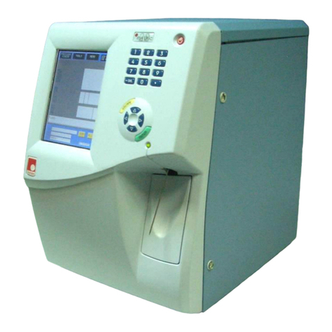
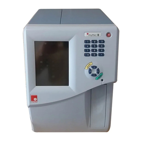
Orphee mythic 22 User manual

MYTHIC 22
Copyright© Orphée SA. All Rights Reserved.
Page 1/105
mythic 22
User’s Manual

1. INSTALLATION
REF : M22/UM/EN/015
Page 2/105
Copyright© Orphée SA. All Rights Reserved.
MYTHIC 22
REVISIONS
Revision Nb Date Author Software Comments
07
26/11/10
CM
≥ V2.3.8
Add flag 'S' for PLT Chap. 8.5.1.
Update chapter 9.1.2.
Update consumptions (Chap. 4.2).
Update Hydraulic diagram and tubing list
08
09
10
11
12
13
14
15
05/03/12
18/10/12
06/07/15
12/10/16
14/03/2019
02/04/2019
06/09/2019
13/05/2020
OM
HC
VC
VC
JA
ML
SK, KZ
ML
≥ V2.4.0
≥ V2.4.0
≥ V3.1.0 or ≥ V2.5.0
≥ V3.2.0 or ≥ V2.6.0
≥V3.2.1
≥V3.2.1 or 2.6.1
≥V3.2.2
≥V3.2.2
Add IVD & CE logo
Update chapter 9.1.2
New CE declaration.
Add new parameters and reagent protection.
Update setup option (Chap. 3.4)
Update reagent Specification according to new CLP
requirements (chap. 4.3).
Update consumption (Chap. 4.2)
Add “handcrush” warning label (safety instructions)
Add. various information (cleaning and maintenance)
All sections modified
Update reagents cycles, cutting table, counters
CONTACT ADDRESS
MANUFACTURER
Manufactured in Germany for:
ORPHEE SA
19, chemin du champ des filles
CH-1228 Geneva / Plan-les-Ouates
SWITZERLAND
Tel : +41 (0) 22 706 1840
Fax : +41 (0) 22 794 4391
http://www.orphee-medical.com
LOCAL AGENT

MYTHIC 22
Copyright© Orphée SA. All Rights Reserved.
Page 3/105
READ
THIS
BEFORE
USING
THE
EQUIPMENT
WARNING! RISK OF DANGER! Indicates a procedure to be strictly respected in
order to avoid any risks for the operator (user) or damages on the instrument or
on the quality of results.
Indicates that wearing gloves is mandatory
before performing the described
operation due to risk of contact with materials that may be infectious.
Indicates hot temperatures surfaces and risk of burns
Do not touch directly while
the machine is turned on. To avoid risk of burning injuries, be
sure to wait 30 min
after the device power is off before directly touching the areas marked with this
symbol.
Indicates that moving parts can cut and crush. Risk of pinch point.
Keep hands clear while operating the machine.
NOTA
Indicates important additional information.
DANGER
Misuse of electrical equipment may cause electrocution, burns, fire and other hazards.
Check that the voltage setting matches the supply voltage.
Protective earthing is required, plug the MYTHIC 22 into a supply outlet which has an earth connection.
Preserve a good access to the supply outlet to be able to unplug the MYTHIC 22 in emergency case.
Do not place the power supply adapter in liquid, nor put it where it could fall into liquid. If the power supply adapter
becomes wet, unplug it before touching it.
Do not use the MYTHIC 22 if it is not working properly, or if it has suffered any damage ( damage to the supply cord
or its plug; damaged caused by dropping the power supply adapter).
Do not let the power supply adapter or its flexible cord come into contact with surfaces which are too hot to touch.
Do not place anything on top of the MYTHIC 22.
Do not use the MYTHIC 22 where aerosol sprays are being used, or where oxygen is being administered.
Do not use the MYTHIC 22 out of doors.
Always switch off the MYTHIC 22 and disconnect the power adaptor before dismantling any part.
The MYTHIC 22 is an automated hematology analyzer for in vitro diagnostic use in clinical laboratories by an
authorized people.
- Only human blood or artificial control blood should be run.
- Only the reagents mentioned in this manual are permitted to use.
- The optimum performances can be only achieved if the calibration, controls check, cleaning and maintenance
procedures are carefully followed.
Due to the use of this equipment, all parts and surfaces of the MYTHIC 22 are potentially infective. Wearing rubber
gloves is highly recommended and after completion of work, washes hands with disinfectant.
Always replace or use parts of the equipment by parts supplied by ORPHEE distributor.
Basic safety precautions should always be taken. If the equipment is not used according to the manufacturer’s
instructions, the protective by the equipment may be impaired.
The treatment of waste and the elimination of a part or the complete instrument must be done in compliance with the
local legislation.
Any output or input connections (except the printer and the barcode reader supplied by ORPHEE) cannot be done
without the ORPHEE representative authorization.
Do not open the door located on the right side of the instrument (see section 1.1.3) when a hydraulic cycle is in
progress for it would lead to an immediate stop. To re-start, shut the door and run a Control cycle (see section 9.4.1).

1. INSTALLATION
REF : M22/UM/EN/015
Page 4/105
Copyright© Orphée SA. All Rights Reserved.
MYTHIC 22
KEEP THESE INSTRUCTIONS
This equipment needs special precautions regarding general requirements for safety.
Guidance and manufacturer’s declaration – electromagnetic emissions.
The MYTHIC 22 is intended for use in the electromagnetic environment specified below. The customer or
the user of the MYTHIC 22 should assure that it is used in such an environment.
Emmissions test
Compliance level
Electromagnetic environment - guidance
Harmonic emissions
IEC 61000-3-2
Class A
The MYTHIC 22 is suitable for use in all establishments, including
domestic establishments and those directly connected to the public
low-voltage power supply network that supplies buildings used for
domestic purposes.
Voltage fluctuations/flicker
emissions
IEC 61000-3-3
Complies
Guidance and manufacturer’s declaration – electromagnetic immunity.
The MYTHIC 22 is intended for use in the electromagnetic environment specified below. The customer or
the user of the MYTHIC 22 should assure that it is used in such an environment.
Immunity test
IEC 60601 test level
Compliance
level
Electromagnetic environment - guidance
Electrostatic
discharge (ESD)
IEC 61000-4-2
±6 kV contact
±8 kV air
Complies
Floors should be wood, concrete or ceramic tile. If floors
are covered with synthetic material, the relative
humidity should be at least 30 %.
Electrical fast
transient/burst
IEC 61000-4-4
±2 kV for power supply lines
±1 kV for input/output lines
Complies
Mains power quality should be that of a typical
commercial or hospital environment.
Surge
IEC 61000-4-5
±1 kV differential mode
±2 kV common mode
Complies
Mains power quality should be that of a typical
commercial or hospital environment.
Voltage dips, short
interruptions and
voltage variations
on power supply
input lines
IEC 61000-4-11
<5 %
U
T
(>95 % dip in
U
T) for 0,5 cycle
40 %
U
T
(60 % dip in
U
T) for 5 cycles
70 %
U
T
(30 % dip in
U
T) for 25 cycles
<5 %
U
T
(>95 % dip in
U
T) for 5 sec
Complies
Mains power quality should be that of a typical
commercial or hospital environment. If the user of the
MYTHIC 22 requires continued operation during power
mains interruptions, it is recommended that the MYTHIC
22 be powered from an uninterruptible power
supply or a battery.
Power frequency
(50/60 Hz)
magnetic field
IEC 61000-4-8
3 A/m
Complies
Power frequency magnetic fields should be at levels
characteristic of a typical location in a typical commercial
or hospital environment.
NOTE
U
T is the a.c. mains voltage prior to application of the test level.

MYTHIC 22
Copyright© Orphée SA. All Rights Reserved.
Page 5/105
Guidance and manufacturer’s declaration – electromagnetic immunity.
The MYTHIC 22 is intended for use in the electromagnetic environment specified below. The customer or
the user of the MYTHIC 22 should assure that it is used in such an environment.
Immunity test
IEC 60601 test level
Compliance
level
Electromagnetic environment - guidance
Portable and mobile RF communications equipment should
be used no closer to any part of the MYTHIC 22,
including cables, than the recommended separation
distance calculated from the equation applicable to the
frequency of the transmitter.
Recommended separation distance
Conducted RF
IEC 61000-4-6
3 Vrms
150Khz to 80Mhz
3 Vrms
d
= 1,2√
P
Radiated RF
IEC 61000-4-3
3 Vrms
80Mhz to 2,5Ghz
3 Vrms
d
= 1,2√
P
80MHz to 800MHz
d
= 2,3√
P
800MHz to 2,5GHz
Where P is the maximum output power rating of the
transmitter in watts (W) according to the transmitter
manufacturer and d is the recommended separation
distance in meters (m).
Field strengths from fixed RF transmitters, as
determined by an electromagnetic site survey,ashould be
less than the compliance level in each frequency range.
Interference may occur in the vicinity of equipment
marked with the following symbol:
.
NOTE 1 At 80Mhz and 800MHz, the higher frequency range applies.
NOTE 2 Theses guidelines may not apply in all situations. Electromagnetic propagation is affected by absorption and reflection from
structures, objects and people.
aField strengths from fixed transmitters, such as base stations for radio (cellular/cordless) telephones and land mobile radios,
amateur radio, AM an FM radio broadcast and TV broadcast cannot be predicted theoretically with accuracy. To assess the
electromagnetic environment due to fixed RF transmitters, an electromagnetic site survey should considered. If the measured field
strength in the location in which the MYTHIC 22 is used exceeds the applicable RF compliance level above, the MYTHIC 22 should be
observed to verify normal operation. If abnormal performance is observed, additional measures may be necessary, such as re-orienting
or relocating the MYTHIC 22.
b
Over the frequency range 150KHz to 80MHz, field strengths should be less than 3V/m.
The symbol on the product indicates that this product may not be treated as household waste. Instead it shall be handed
over the applicable collection point for the recycling of electrical and electronic equipment. By ensuring this product is disposed of
correctly, you will help prevent potential negative consequences for the environment and human health, which could otherwise be
caused by inappropriate waste handling of this product. For more detailed information about recycling of this product, please
contact your local city office or your distributor of this product.

1. INSTALLATION
REF : M22/UM/EN/015
Page 6/105
Copyright© Orphée SA. All Rights Reserved.
MYTHIC 22
TABLE OF CONTENTS
READ THIS BEFORE USING THE EQUIPMENT...........................................................................3
1. INSTALLATION .................................................................................................8
1.1 UNPACKING............................................................................................................................................................................. 8
1.1.1 Introduction ...................................................................................................................................................................................... 8
1.1.2 Unpacking Procedure.......................................................................................................................................................................... 8
1.1.3 Visual checking...................................................................................................................................................................................10
1.2 INSTALLATION CONSTRAINTS ............................................................................................................................................................10
1.2.1 Installation place...............................................................................................................................................................................10
1.2.2 Installation environment..................................................................................................................................................................10
1.3 ELECTRICAL CONNECTIONS.................................................................................................................................................................. 11
1.3.1 Power supply block............................................................................................................................................................................. 11
1.4 PRINTER CONNECTION .......................................................................................................................................................................... 11
1.5 CONNECTION,CHANGE AND PRIMING REAGENTS ...............................................................................................................................12
1.5.1 Connection...........................................................................................................................................................................................12
1.5.2 Priming ................................................................................................................................................................................................13
1.5.3 Diluent priming: .................................................................................................................................................................................15
1.5.4 Lyse priming:......................................................................................................................................................................................15
1.5.5 Cleaner priming..................................................................................................................................................................................15
1.5.6 Waste setting:...................................................................................................................................................................................16
1.6 TRANSPORTATION AND STORAGE ........................................................................................................................................................16
2. GENERAL OVERVIEW .................................................................................................. 17
2.1 GENERALITIES.......................................................................................................................................................................................17
2.2 OVERVIEW.............................................................................................................................................................................................18
2.3 MAIN PART DESCRIPTION ....................................................................................................................................................................19
2.3.1 Display / Keyboard............................................................................................................................................................................19
2.3.2 Main Menu description.................................................................................................................................................................... 20
2.3.3 Dilution hydraulic part.....................................................................................................................................................................21
2.3.4 Mono electronic board.................................................................................................................................................................... 22
2.3.5 Power Supply Block.......................................................................................................................................................................... 22
2.3.6 Reagent tray..................................................................................................................................................................................... 23
3. INSTRUMENT SET UP ................................................................................................. 24
3.1 USER’S IDENTIFICATION.................................................................................................................................................................... 24
3.1.1 Login.................................................................................................................................................................................................... 24
3.1.2 In process ......................................................................................................................................................................................... 24
3.2 SYSTEM STATUS.................................................................................................................................................................................. 25
3.3 SET UP .................................................................................................................................................................................................. 26
3.4 ADVANCED SET-UP............................................................................................................................................................................... 27
3.4.1 Printer set up: .................................................................................................................................................................................. 27
3.4.2 Communication: ................................................................................................................................................................................ 27
3.4.3 Analysis options:.............................................................................................................................................................................. 28
3.4.4 Lab. parameters:.............................................................................................................................................................................. 28
3.4.4.1 Limits:............................................................................................................................................................................................. 29
3.4.4.2 Thresholds: ................................................................................................................................................................................... 30
3.4.4.3 Flags level:......................................................................................................................................................................................31
3.4.4.4 Correction factors:.......................................................................................................................................................................31
3.4.5 Calibration factor:........................................................................................................................................................................... 32
3.4.6 Other Setting:................................................................................................................................................................................. 32
3.4.7 Storage options: .............................................................................................................................................................................. 32
3.4.8 Version release:............................................................................................................................................................................... 34
4. SPECIFICATIONS ...................................................................................................... 35
4.1 ANALYTICAL SPECIFICATIONS ........................................................................................................................................................... 35
4.2 PHYSICAL SPECIFICATIONS................................................................................................................................................................ 38
4.3 REAGENTS SPECIFICATIONS .............................................................................................................................................................. 40
4.3.1 Diluent for Mythic 22 ..................................................................................................................................................................... 40
4.3.2“OnlyOne”............................................................................................................................................................................................41
4.3.3 Cleaner for Mythic 22.................................................................................................................................................................... 42
4.3.4 Mythic 18-22 FLUSH – CLEANER................................................................................................................................................. 43
4.4 ANALYTICAL LIMITATIONS ................................................................................................................................................................ 44

MYTHIC 22
Copyright© Orphée SA. All Rights Reserved.
Page 7/105
4.4.1 Recommendations............................................................................................................................................................................. 44
4.4.2 Interferences.................................................................................................................................................................................. 44
5. SAMPLE ANALYSIS .................................................................................................... 49
5.1 VERIFICATIONS BEFORE STARTING.................................................................................................................................................... 49
5.2 START UP.............................................................................................................................................................................................. 49
5.3 REAGENT REPLACEMENT ...................................................................................................................................................................... 50
5.4 START UP...............................................................................................................................................................................................51
5.5 PREPARATIONS BEFORE ANALYSIS ......................................................................................................................................................51
5.6 ANALYSIS............................................................................................................................................................................................. 52
5.6.1 Introduction ..................................................................................................................................................................................... 52
5.6.2 Sample Identification..................................................................................................................................................................... 52
5.6.3 Sample run........................................................................................................................................................................................ 54
5.7 RESULTS ............................................................................................................................................................................................... 55
5.8 PRINTING ............................................................................................................................................................................................. 57
5.8.1 Model report (A4) – external printer........................................................................................................................................... 57
5.8.2 Model report – Thermal printer.................................................................................................................................................... 58
5.9 LOGS ..................................................................................................................................................................................................... 59
5.10 ARCHIVE ............................................................................................................................................................................................. 59
5.10.1 Results ............................................................................................................................................................................................. 60
5.10.2 View...................................................................................................................................................................................................61
5.11 STAND BY AND SHUT DOWN.............................................................................................................................................................. 62
6. QUALITY CONTROL .................................................................................................... 63
6.1 INTRODUCTION.................................................................................................................................................................................... 63
6.2 QC ........................................................................................................................................................................................................ 63
6.2.1 Change................................................................................................................................................................................................ 64
6.2.2 Run control blood............................................................................................................................................................................. 65
6.2.3 Levey-Jennings graph ..................................................................................................................................................................... 66
6.2.4 Restore.............................................................................................................................................................................................. 66
6.3 REPEATABILITY.................................................................................................................................................................................... 66
7. CALIBRATION .......................................................................................................... 68
7.1 RESULTS................................................................................................................................................................................................ 69
7.1.1 Calibration blood analysis ................................................................................................................................................................ 69
7.1.2 Calibration ......................................................................................................................................................................................... 70
7.2 TARGET VALUE MODIFICATIONS......................................................................................................................................................... 70
8. TECHNOLOGY ........................................................................................................... 72
8.1 DETECTION PRINCIPLE ......................................................................................................................................................................... 72
8.1.1 WBC, RBC, PLT Counting.................................................................................................................................................................. 72
8.1.2 Five-part diff measurement........................................................................................................................................................... 73
8.1.3 Hemoglobin measurement ............................................................................................................................................................... 74
8.2 LEUCOCYTE ANALYSIS ......................................................................................................................................................................... 75
8.3 ERYTHROCYTE ANALYSIS .................................................................................................................................................................... 76
8.4 ANALYSIS OF PLATELETS .................................................................................................................................................................... 77
8.5 FLAGS ................................................................................................................................................................................................... 78
8.5.1 General Flags .................................................................................................................................................................................... 78
8.5.2 Instrument Flags............................................................................................................................................................................. 78
8.5.3 Leucocytes Flags ............................................................................................................................................................................. 79
8.5.4 Erythrocyte and HGB Flags........................................................................................................................................................... 80
8.5.5 Platelets Flags.................................................................................................................................................................................. 80
8.5.6 QC Flags............................................................................................................................................................................................ 80
8.5.7 STARTUP Flags ............................................................................................................................................................................... 80
8.6 HYDRAULIC DESCRIPTION ....................................................................................................................................................................81
8.6.1 Sampling module................................................................................................................................................................................81
8.6.2 Counting bath module.......................................................................................................................................................................81
8.6.3 Syringes module................................................................................................................................................................................81
8.6.4 Optical manifold ...............................................................................................................................................................................81
8.6.5 Optical bench................................................................................................................................................................................... 82
8.7 SOFTWARE ........................................................................................................................................................................................... 82
8.7.1 Windows ............................................................................................................................................................................................ 82
8.7.2 Menu tree ......................................................................................................................................................................................... 83
9. SERVICE ................................................................................................................. 84
9.1 MAINTENANCE ..................................................................................................................................................................................... 84
9.1.1 Maintenance table ............................................................................................................................................................................ 84

1. INSTALLATION
REF : M22/UM/EN/015
Page 8/105
Copyright© Orphée SA. All Rights Reserved.
MYTHIC 22
9.1.2 Concentrate cleaning with hypochlorite....................................................................................................................................... 85
9.1.3 Piston greasing.................................................................................................................................................................................. 86
9.2 HYDRAULIC CYCLES.............................................................................................................................................................................. 87
9.3 MECHANICS.......................................................................................................................................................................................... 88
9.4 REPAIRING............................................................................................................................................................................................ 89
9.4.1 Emergency stop................................................................................................................................................................................ 89
9.4.2 Needle or o-ring replacement ....................................................................................................................................................... 90
9.4.3 Baths dismantling ............................................................................................................................................................................ 92
9.4.4 Baths o-ring replacement............................................................................................................................................................... 95
9.4.5 Aperture counting head replacement........................................................................................................................................... 95
9.5 TROUBLESHOOTING............................................................................................................................................................................. 96
9.5.1 Analytical problems ......................................................................................................................................................................... 96
9.5.2 Other problems ............................................................................................................................................................................... 97
9.5.3 Disinfection procedure................................................................................................................................................................... 98
9.6 TROUBLESHOOTING MESSAGES.......................................................................................................................................................... 99
9.7 LOGS ERRORS ..................................................................................................................................................................................... 103
9.8 HYDRAULIC DIAGRAM ........................................................................................................................................................................ 104
1. INSTALLATION
1.1 UNPACKING
1.1.1 Introduction
The MYTHIC 22 is an automated hematology analyzer for in vitro diagnostic use in clinical laboratories by an
authorized people.
- Only human blood or artificial control blood should be run.
- Only the reagents mentioned in this manual are permitted to use.
- The optimum performances can only be achieved if the calibration, controls check, cleaning and
maintenance procedures are carefully followed
If the MYTHIC 22 has been stored at a temperature less than 10°C it must be left at room
temperature during 24 hours.
It must be calibrated at each displacement and installation (See section 7).
1.1.2 Unpacking Procedure
Before unpacking the instrument, we recommend to check the box of the instrument and notify any damage
to the carrier.
-Open the box on the top, remove the starter kit.
-Remove the MYTHIC 22 from the box.

MYTHIC 22
Copyright© Orphée SA. All Rights Reserved.
Page 9/105
Check the Installation and Maintenance kit contents:
INSTALLATION KIT
QTY
Designation
Part Number
1
M22- DILUENT
005-1002-90 23 -01
1
M18 - WASTE
005-1011-90 24
1
150W switching adapter
050-1001-01 150 24
1
European Power line cord
150-2001-CEE C13 1000
2
5/10-20L Adaptator
300-1009-05 1020
1
M22C User manual
N/C
1
MYTHIC 22 Installation Report
N/C
1
MYTHIC 22 Quality Control Certificate
N/C
1
Screwdriver Slot 1/4"
700-7101-02
MAINTENANCE KIT Box 18/22
QTY
Designation
Part Number
1
Tygon tubing 1.52x3.2mm(1000mm)
300-0502- 016 032
1
Tygon tubing 2.06x4mm(500mm)
300-0502-020 040
1
Tygon tubing 1.02x2.7mm(500mm)(for Mythic
22)
300-0502-010
1
Tygon tubing 1.3x3mm(500mm)
300-0502-013 030
1
Tubing 9 1.3x3mm (425mm)
N/C
1
Tubing 10 M22 0.9 x2.4 (500mm)
N/C
1
Tubing 10 M18 0.9 x 2.4 (375mm)
N/C
1
Tubing 50 (for Mythic 22)
005-1002-90-50
5
Cables Ties
153-0101-100 25
1
O-Ring 1.4x1.25mm, needle O-ring
312-0505-1310 160
2
O-ring 5x1mm, Counting heads O-rings
312-0505-140 125 010
2
O-rings 13.1x1.6mm, Counting baths O-rings
312-0505-500 100
1
1L flexible straw
005-1001-06 02
1
Silicon grease (3gr)
410-0501-02 02
1
Short Arm TORX T10 Tool
700-1101-10
1
Short Arm TORX T20 Tool
700-1101-20

1. INSTALLATION
REF : M22/UM/EN/015
Page 10/105
Copyright© Orphée SA. All Rights Reserved.
MYTHIC 22
1.1.3 Visual checking
HAZARDOUS MOVING PARTS, BEWARE TO STAY AWAY FROM THESE PARTS WHEN THE
MACHINE IS SWITCH ON.
1.2 INSTALLATION CONSTRAINTS
1.2.1 Installation place
To ensure that the MYTHIC 22 fulfills its function, place the instrument on a table that supports the
weight of the instrument, printer and reagents (around 40 Kg). Leave a space of 10 cm in the rear of the
instrument to ensure a well-ventilated place. Avoid a place that can be exposed to direct sunlight.
1.2.2 Installation environment
a) Indoor use;
b) Altitude up to 2 000 m;
c) Temperature 18 °C to 34 °C; (max 25° for lyse );
d) Maximum relative humidity 80 % for temperatures up to 31 °C decreasing linearly to 50 % relative
humidity at 40 °C;
e) MAINS supply voltage fluctuations up to ±10 % of the nominal voltage;
1
2
3
Open the door on the right side with the tool
provided in the kit.
To be checked:
1. Counting chambers perfectly locked
in their manifold locations.
2. Needle’s dismountable system
located in the rocker.
3. Rocker in front position at the
maximum course.

MYTHIC 22
Copyright© Orphée SA. All Rights Reserved.
Page 11/105
f) Transient over voltages typically present on the MAINS supply;
g) Rated pollution degree II.
Please contact Orphée’s representative if you want to use the instrument in special conditions (height higher
than 2000 m or special power supply conditions).
1.3 ELECTRICAL CONNECTIONS
All the connectors are in the rear of the MYTHIC 22
CONNECTION :
SYMBOL :
- 2 USB ports (section 3.4.7) :
- Ethernet connection (TCP/IP) :
- External barcode reader (RS232C) :
- Host connection (RS232C) :
- Printer connection (Centronics) :
- Power supply cord connection :
- Equipotential grounding connection :
Any output or input connections (except the printer and the bar code
reader supplied by
ORPHEE) cannot be done without the ORPHEE representative authorization.
1.3.1 Power supply block
MYTHIC 22 must be connected to the power with the power supply block provided with the starter kit.
Choose a well-ventilated place for the block and be sure to connect this power supply in a socket-outlet with
a correct earth connection.
The power supply block must be placed at the rear of the MYTHIC 22 and, if possible in an upper position to
avoid the contact with any liquid.
To disconnect electrically the MYTHIC 22, remove the power supply plug from the main circuit.
- In the case of replacement of the main power wire supplied with the MYTHIC 22 the new
one must comply with the local regulation (3
1.5mm cable and 250V 10A plug).
-
The MYTHIC 22 has been certified with the power supply box provided with the machine.
The use of another external power supply box is not guaranteed.
Please contact your
Orphée’s representative.
1.4 PRINTER CONNECTION
Connect the printer cable in conformity with the printer user’s manual.
Use the parallel rear plug of the MYTHIC 22 ( )or the USB plug ( ) to connect the printer
cable. Select the printer driver (section 3.3). Check earth connection of printer to be same as the earth of
Mythic.

1. INSTALLATION
REF : M22/UM/EN/015
Page 12/105
Copyright© Orphée SA. All Rights Reserved.
MYTHIC 22
1.5 CONNECTION, CHANGE AND PRIMING REAGENTS
MYTHIC 22 works exclusively with the reagents described in section 4.3. Orphee’s or its
local representative will not be responsible for the quality of the results and for the
maintenance of the instrument if other commercial reagents are used.
Warranty does not cover any defect, malfunction or damage due to failure to use the
inappropriate reagents or chemicals specified for the product.
MYTHIC 22 can be configured in specific Reagent mode with encrypting in order to be used
only with Orphee’s reagents. Please contact your Orphee’s representative.
1.5.1 Connection
Lyse reagent and cleaning solution:
Before handling the reagents, read carefully their
specifications described in section 4.3.
- Remove the door on the left side of the instrument.
- Put the reagent bottles in the dedicated location.
- Remove the caps of the bottles.
- Tighten the red caps on the Lyse bottle (red sticker) and the
blue one on the cleaning solution bottle (blue sticker).
Diluent and waste:
- Connect the diluent tube (male connector) on the outlet on the bottom
and tighten the cap on the diluent container.
- To use a 20-liter diluent container adds the tubing straw adaptor
supplied with the installation kit.
- Connect the waste tube (female connector) on the outlet on the top
and tighten the cap on an empty container.
Do not modify the type and the length of the diluent
and waste tubes.
The diluent must be placed at the same level
as the
MYTHIC 22.
Collect the waste in a container preferably placed on
the floor and treat it in compliance with your local
legislation.
Example of neutralization procedure usually used in a laboratory for waste material:
For 20 liters of waste, produced by the MYTHIC 22, add 50 ml of a solution of sodium hydroxide (NaOH)
at 200g/l, mix the container, add 100ml of bleach at 36°C, mix the container, wait one hour before empty
it.
Only use this procedure if there is no specific local legislation for the treatment of the
waste.
Diluent
Waste

MYTHIC 22
Copyright© Orphée SA. All Rights Reserved.
Page 13/105
1.5.2 Priming
When first starting the MYTHIC 22, it is necessary to perform a complete prime of the fluidic circuit.
Before starting, be sure that all the reagent and waste tubes are properly connected.
The reagents must be stored minimum 24 hours at room temperature before use.
Priming procedure :
Switch on:
- Connect the power supply block.
- Press the ON/OFF button.
- The cycle LED turns red. No cycle can be performed before it turns
green.
- The information window could stay up to 3 mn to enable the update of all
the files.
Login:
- The operator’s identification display appears.
- Enter the user’s identification, the password (see section 3.1) and press
to validate.
- AUTONOMY (run) indicates the number of samples (runs) you can
perform (calculated with the smaller quantity of reagents).
- If this window appears, it means that several
results in memory have not been sent before
the MYTHIC 22 was switched off.
- Press YES to send them immediately or press
LATER to wait at another time or NO if you do
not want to send them.
- No USB key is available, connect an USB key then press YES or see section 3.4.7
to change the archive mode.

1. INSTALLATION
REF : M22/UM/EN/015
Page 14/105
Copyright© Orphée SA. All Rights Reserved.
MYTHIC 22
System priming:
- The main menu is displayed.
- Press on .
NOTA
To execute an emergency stop push shortly on the switch
on/off button .
- Press : The MYTHIC 22 performs a complete priming
cycle.
- The cycle LED turns red. No cycle can be performed before it turns
green.
- AUTONOMY (run) indicates the number of samples runs.
- To prime or to know the quantity of reagent press the dedicated button.
- Press to visualize the cycle counters.
- To reset the counter with the button , please contact
your Orphée’s representative.

MYTHIC 22
Copyright© Orphée SA. All Rights Reserved.
Page 15/105
1.5.3 Diluent priming:
- From the MAIN MENU press then to
have access to this screen.
- IF THE REAGENT MODE WITH ENCRYPTING IS ACTIVATED, LOT,
EXPIRY, SERIAL AND CODE FIELDS, MUST BE ONLY FILLED BY
BARCODES SCANNING.
- IF THE REAGENT MODE WITH ENCRYPTING IS NOT ACTIVATED,
LOT AND EXPIRY CAN BE FILLED MANUALLY OR BY BARCODE
SCANNING.
- Press to validate the new entry or after changing a
new container with the same information.
- After the replacement of a new container or to prime the diluent, press
- A new entry is automatically done in the logs (see section 5.9).
1.5.4 Lyse priming:
- From the MAIN MENU press then to
have access to this screen.
- IF THE REAGENT MODE WITH ENCRYPTING IS ACTIVATED, LOT,
EXPIRY, SERIAL AND CODE FIELDS, MUST BE ONLY FILLED BY
BARCODES SCANNING.
- IF THE REAGENT MODE WITH ENCRYPTING IS NOT ACTIVATED,
LOT AND EXPIRY CAN BE FILLED MANUALLY OR BY BARCODE
SCANNING.
- Press to validate the new entry or after changing a
new container with the same information.
- After the replacement of a new container or to prime the lyse, press
.
- A new entry is automatically done in the logs (see section 5.9).
1.5.5 Cleaner priming
- From the MAIN MENU press then to
have access to this screen.
- IF THE REAGENT MODE WITH ENCRYPTING IS ACTIVATED, LOT,
EXPIRY, SERIAL AND CODE FIELDS, MUST BE ONLY FILLED BY
BARCODES SCANNING.
- IF THE REAGENT MODE WITH ENCRYPTING IS NOT ACTIVATED,
LOT AND EXPIRY CAN BE FILLED MANUALLY OR BY BARCODE
SCANNING.
- Press to validate the new entry or after changing a
new container with the same information.
- After the replacement of a new container or to prime the cleaner, press
.
- A new entry is automatically done in the logs (see section 5.9).

1. INSTALLATION
REF : M22/UM/EN/015
Page 16/105
Copyright© Orphée SA. All Rights Reserved.
MYTHIC 22
1.5.6 Waste setting:
- Enter only the capacity of the container.
- After replacement of the waste container press to
reset to initialize the waste calculation.
1.6 TRANSPORTATION AND STORAGE
Storage temperature: -10°C to +50°C.
If the MYTHIC 22 has been stored at a temperature less than 10°C it must be left at room temperature for
24 hours.
Before transportation outside the laboratory, perform a complete cleaning with a disinfectant in compliance
with the local legislation. Please use the CLEANOUT procedure, for details contact your local ORPHEE’S
representative.
Transportation requirements:
•Keep the parcel, packaging and box containing the device DRY at all times.
•The Mythic 22 is very fragile, has breakable parts, and must be handled cautiously.
•The box containing the device must be handled put down or moved keeping the designated face up at
all times. It must not be tilted.
•Don’t pile up more than TWO boxes containing devices, either for transportation or long term
storage.
Perform a calibration, section 7and a quality control, section 6, then the
MYTHIC 22 WILL BE READY TO OPERATE.

2. GENERAL OVERVIEW
REF : M22/UM/EN/014
MYTHIC 22
Copyright© Orphée SA. All Rights Reserved.
Page 17/105
2. GENERAL OVERVIEW
2.1 GENERALITIES
The MYTHIC 22 is an automated hematology analyzer for in vitro diagnostic use in clinical laboratories by an
authorized and trained people.
- Only human blood or artificial blood (recommended ORPHEE controls or calibrators) should be run.
- Only the reagents mentioned in this manual are permitted to be used.
- The optimum performances can be only achieved if the calibration, controls check, cleaning and
maintenance procedures are carefully followed (see section 9.1).
MYTHIC 22 is a fully automated analyzer performing hematological analysis on whole blood collected on
EDTA K2 or K3 tubes.
-Sample volume: 15,7 µl (inside the needle, the total volume could be upper in function of the blood
remaining outside of the needle).
-Throughput: > 45 samples/hour.
-24 analysis parameters in DIF mode and 12 parameters in CBC mode:
Leukocyte parameters:
WBC White Blood Cells
LYM Lymphocytes in % (DIF mode only)
LYM Lymphocytes in # (DIF mode only)
MON Monocytes in % (DIF mode only)
MON Monocytes in # (DIF mode only)
NEU Neutrophils in % (DIF mode only)
NEU Neutrophils in # (DIF mode only)
EOS Eosinophils in % (DIF mode only)
EOS Eosinophils in # (DIF mode only)
BAS Basophiles in % (DIF mode only)
BAS Basophiles in # (DIF mode only)
Erythrocyte parameters:
RBC Red Blood Cells
HGB Hemoglobin
HCT Hematocrit
MCV Mean Corpuscular Volume
MCH Mean Corpuscular Hemoglobin
MCHC Mean Corpuscular Hemoglobin Concentration
RDWC Red Blood cells Distribution Width (CV)
RDWS Red Blood cells Distribution Width (SD)
Thrombocyte parameters:
PLT Platelet
MPV Mean Platelet Volume
PDW*Platelet Distribution Width
PCT*Thrombocrit
PLCR* Platelet Large Cell Ratio
*For Investigation Use only in United States of America.

2. GENERAL OVERVIEW
REF : M22/UM/EN/014
Page 18/105
Copyright© Orphée SA. All Rights Reserved.
MYTHIC 22
2.2 OVERVIEW
MYTHIC 22 consist of 8 main parts:
1. Display / Keyboard.
2. Dilution hydraulic part.
3. Mono electronic board.
4. Reagent tray.
5. Connection.
6. External power supply block.
7. Printer.
8. Barcode reader (option).

REF : M22/UM/EN/014
2. GENERAL OVERVIEW
MYTHIC 22
Copyright© Orphée SA. All Rights Reserved.
Page 19/105
2.3 MAIN PART DESCRIPTION
2.3.1 Display / Keyboard
ON/OFF and
Emergency
STOP
Et
Numeric keyboard
Delete (DEL)
Exit (ESCAPE)
Cursors
Enter (ENTER)
Cycle in process
Led
Color Touch
Screen LCD
display
380*240

2. GENERAL OVERVIEW
REF : M22/UM/EN/014
Page 20/105
Copyright© Orphée SA. All Rights Reserved.
MYTHIC 22
2.3.2 Main Menu description
Back to
previous
screen.
Print, send
select
options.
Direct access
to main
menu.
Start Up
rinsing and
blank control.
Cleaning and
stand by
mode.
Patient archive
(section 5.10)
Quality Control
(section 6).
Calibration
(section 7).
Mythic parameters
(section 3).
Maintenance
and service
menu
Analysis
performing
(section 5.5).
Mythic events
logs
(section 5.9).
Reagent
replacement
(section 5.3).
Log In and
Log Out
(section 3.1).
Date and time.
System status
(section 3.2).
Other manuals for mythic 22
1
Table of contents
Other Orphee Laboratory Equipment manuals
Popular Laboratory Equipment manuals by other brands

Intellinet
Intellinet 561495-UK instructions

Agilent Technologies
Agilent Technologies 1260 Infinity quick start guide

Oxford Instruments
Oxford Instruments ANDOR Kymera 328i Series quick start guide

Binder
Binder KMF 115 operating manual

Grizzly
Grizzly 1160W UVC quick start guide

TESTO
TESTO 872s instruction manual