GeneralOperation
Types of Beeps:
Short beep: Acknowledgment that button was pressed.
Long beep: Input was not accepted, or there was a fault.
Double beep: Unit completed registration or calibration step successfully.
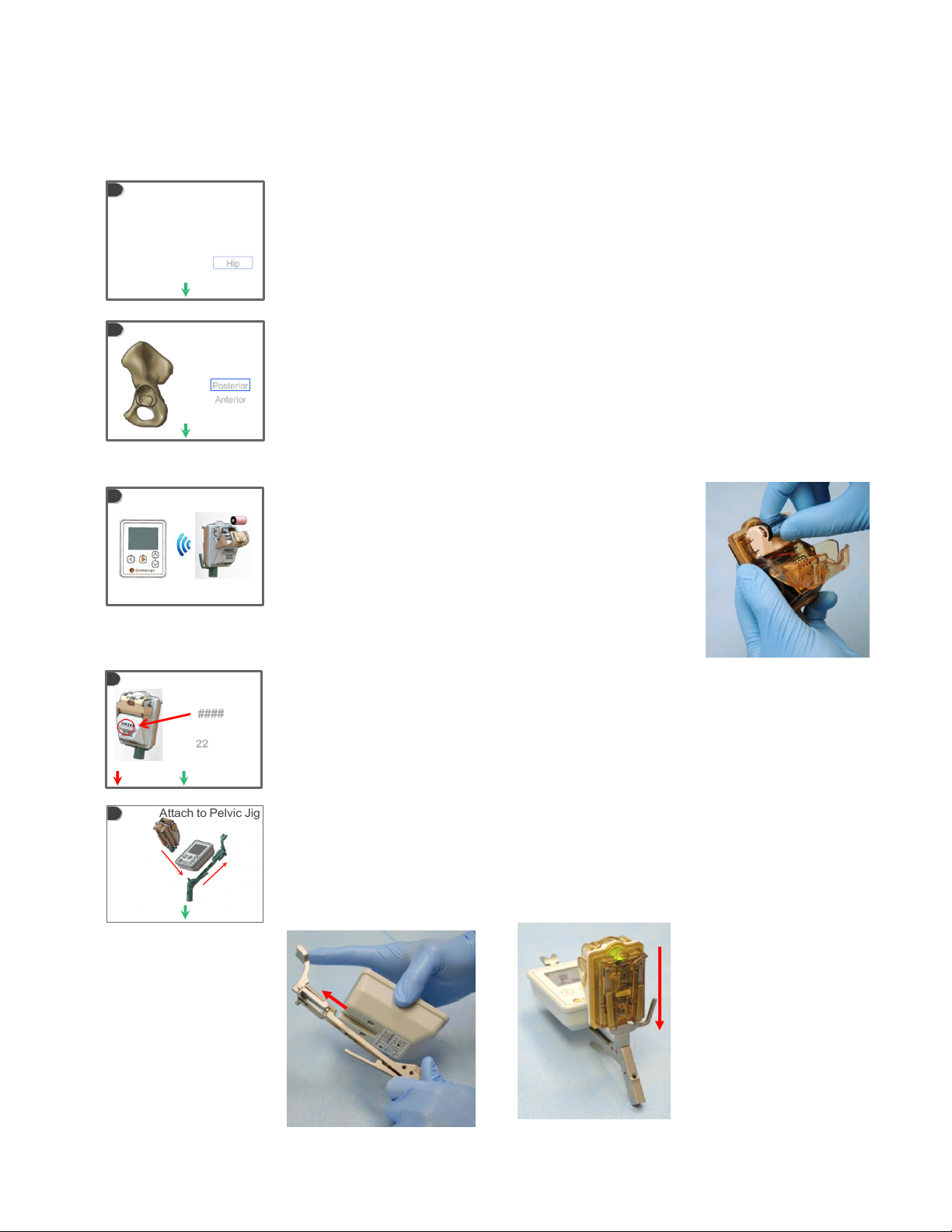
Laser aperture may be open or
closed with the shutter
Left
Returns user to previous screen
Center
Turns unit on and progresses user
to next screen
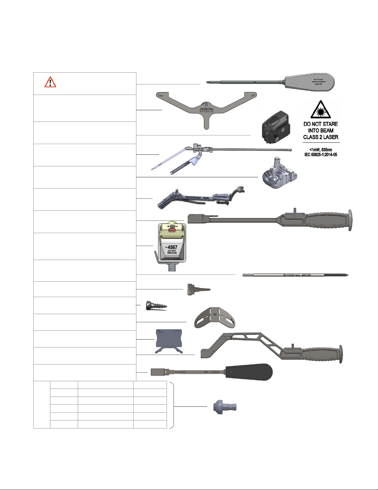
Warnings
NAVIGATION UNIT / REFERENCE SENSOR:
Up and Down
Toggles between different options or
adjusts numerical input
NOTE: Holding Left and Up buttons
simultaneously powers unit off
Risk of communication errors increases if multiple OrthAlign Plus® systems are used in close proximity.
If navigation unit is dropped on floor, it must be discarded. If reference sensor is dropped on floor, it must be returned
to manufacturer for verification of function and calibration.
Probe scale and lens of reference sensor must be kept clean for reliable operation. Note that lens of reference sensor is
on its underside.
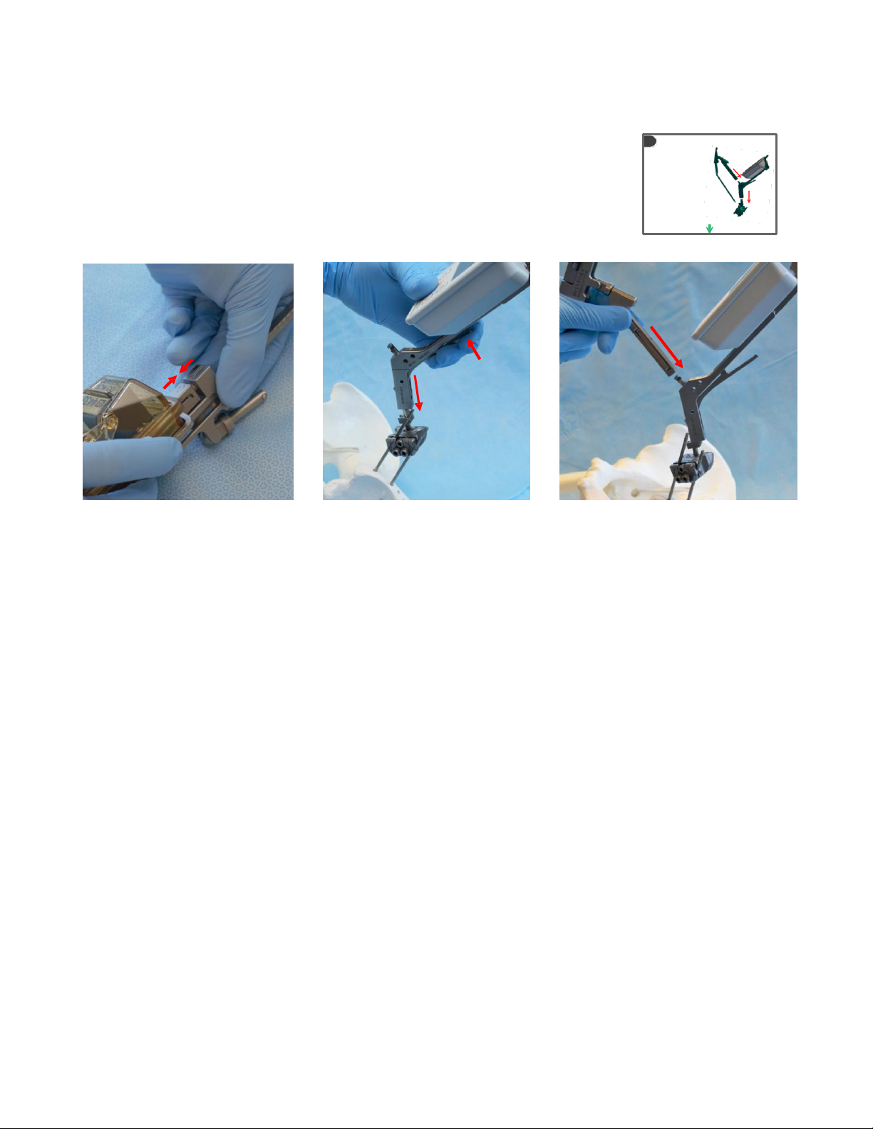
Avoid impacting jig and electronics. Verify position of jig and electronics after impacting and before checking angles.
LASERMODULE/OTHER INSTRUMENTS:
Inspect laser module prior to use. Do not use laser module if it appears damaged or moisture is
present under the lens.
If laser module fails to function after initial registration, abandon leg length and offset measurement
feature.
The laser module is a Class 2 laser product, maximum output: <1mW, emitted wavelength: 635nm,
duration > 0.25 seconds (continuous), beam divergence: 10 degrees, per IEC 60825-1: 2014-
05. This information can be found etched onto the back surface of the laser module.
Do not stare into beam. Eye damage could result.
Take care when using laser to avoid possible dazzle, flash-blindedness or after-image effects.
Use of controls of adjustments or performance of procedures other than those specified herein may result in hazardous
radiationexposure.
Use the movable shutter on the front of the laser module to expose the lens for use, and cover the lens to stop projection
of the laser beam.
Once the battery is installed, the laser is always on and the shutter must be closed to stop projection of the laser beam.
The strong magnetic fields near a neodymium magnet can affect pacemakers, ICDs and other implanted medical devices.
Keep the laser module, vertical laser target, adapter socket driver and any other instruments with magnets at least six inches
away from any such heart device.
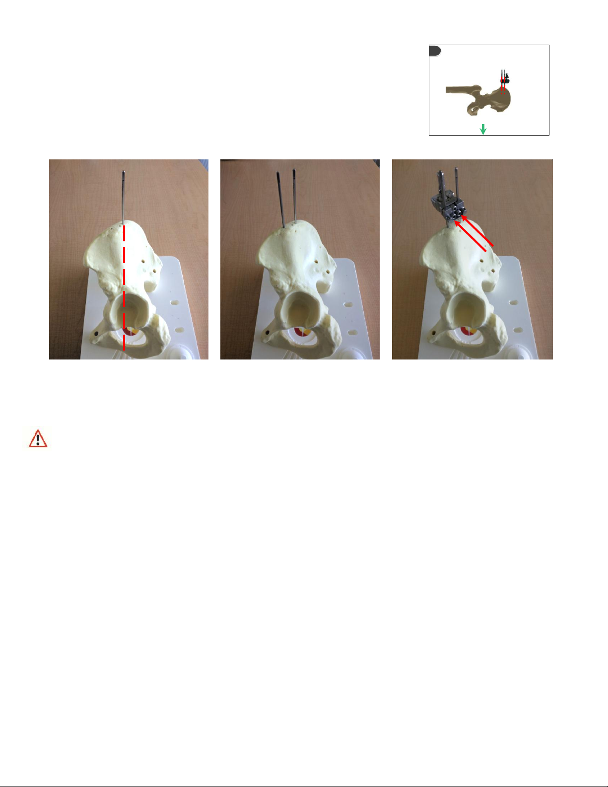
SURGICALTECHNIQUE:
Utilize standard surgical practice in joint reduction (for joint stabilityand soft tissue laxity).
Take care to avoid damage to nervous and vascular structures when using registration probe to register landmarks or
when mounting jig.
Do not impact or hammer system components except where components are designated as impactor devices.
Acetabular shell impactor may be impacted.
Abort the use of the navigation feature if the landmarks cannot be identified or registered.
Remove all pins, screws, and other instruments prior to closing wound. Do not implant any system components.