2. Product description
Ortlieb Präzisionssysteme GmbH & Co. KG • Jurastraße 11 • 73119 Zell unter Aichelberg • Germany
9
Tel.: +49 (0) 7164 797 01-0 • Fax.: +49 (0) 7164 797 01-51 • e-mail: info@ortlieb.net • www.ortlieb.net
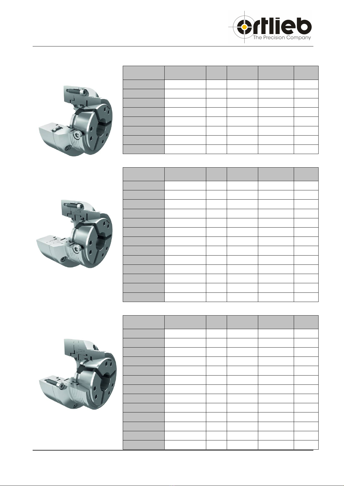
2.2 Technical Data
Chuck
Typ Art. Nr. Fz
max
Fsp
max
Rpm
max. kg
TS 42/5D 036.8010/00 35 kN
80 kN 7000 1/min 5,9 kg
TS 42/6D 036.8011/00 35 kN
80 kN 7000 1/min 7,0 kg
TS 42/140D 036.8012/00 35 kN
80 kN 7000 1/min 5,4 kg
TS 65/5D 036.8020/00 45 kN
105 kN 6000 1/min 8,5 kg
TS 65/6D 036.8021/00 45 kN
105 kN 6000 1/min 7,8 kg
TS 65/8D 036.8022/00 45 kN
105 kN 6000 1/min 11,2kg
TS 65/140D 036.8023/00 45 kN
105 kN 6000 1/min 8,7 kg
TS 65/170D 036.8024/00 45 kN
105 kN 6000 1/min 8,9 kg
Typ Art. Nr. Fz
max
Fsp
max
Rpm
max kg
TS 42/5A 036.8030/00 35 kN
80 kN 7000 1/min 6,4 kg
TS 42/6A 036.8031/00 35 kN
80 kN 7000 1/min 7,4 kg
TS 42/140A 036.8032/00 35 kN
80 kN 7000 1/min 5,8 kg
TS 65/5A 036.8040/00 45 kN
105 kN 6000 1/min 9,3 kg
TS 65/6A 036.8041/00 45 kN
105 kN 6000 1/min 8,6 kg
TS 65/8A 036.8042/00 45 kN
105 kN 6000 1/min 11,0kg
TS 65/140A 036.8043/00 45 kN
105 kN 6000 1/min 9,5 kg
TS 65/170A 036.8044/00 45 kN
105 kN 6000 1/min 9,7 kg
TS 80/6A 036.8051/00 50 kN
115 kN 5500 1/min 13,9 kg
TS 80/8A 036.8052/00 50 kN
115 kN 5500 1/min 14,9 kg
TS 80/140A 036.8055/00 50 kN
115 kN 5500 1/min 15,9 kg
TS 80/170A 036.8053/00 50 kN
115 kN 5500 1/min 13,3 kg
TS 80/220A 036.8054/00 50 kN
115 kN 5500 1/min 15,3 kg
Chuck
Typ Art. Nr. Fz
max
Fsp
max
Rpm
max kg
TS 42/5DL 036.9061/00 35 kN
80 kN 7000 1/min 6,3 kg
TS 42/6DL 036.9062/00 35 kN
80 kN 7000 1/min 7,4 kg
TS 42/140DL 036.9069/00 35 kN
80 kN 7000 1/min 5,9 kg
TS 65/5DL 036.9063/00 45 kN
105 kN 6000 1/min 9,4 kg
TS 65/6DL 036.9070/00 45 kN
105 kN 6000 1/min 8,6 kg
TS 65/8DL 036.9065/00 45 kN
105 kN 6000 1/min 10,8kg
TS 65/140DL 036.9611/00 45 kN
105 kN 6000 1/min 9,6 kg
TS 65/170DL 036.9612/00 45 kN
105 kN 6000 1/min 9,8 kg
TS 80/6DL 036.8061/00 50 kN
115 kN 5500 1/min 14,2 kg
TS 80/8DL 036.8062/00 50 kN
115 kN 5500 1/min 15,1 kg
TS 80/140DL 036.8065/00 50 kN
115 kN 5500 1/min 16,1 kg
TS 80/170DL 036.8063/00 50 kN
115 kN 5500 1/min 13,5 kg
TS 80/220DL 036.8064/00 50 kN
115 kN 5500 1/min 15,5 kg