Blichmann Fermenator Quick guide

Fermenator™© Blichmann Engineering, LLC 2019 1
Fermenator
Operation, Assembly, Maintenance
Congratulations on your purchase, and thank you for selecting the Fermenator™
stainless conical fermentor from Blichmann Engineering™. We are condent that
it will provide you years of service and many gallons of outstanding beer. This
manual will familiarize you with the assembly of the product.
Sections labeled “Warning” can lead to serious injury or death if not followed. Please thoroughly read these sections
and understand them completely before use. If you do not understand them or have any questions, contact your
retailer or Blichmann Engineering (www.BlichmannEngineering.com) before use.
Sections labeled “Caution” can lead to equipment damage or unsatisfactory performance of the equipment. Please
read these sections thoroughly. If you have any questions, contact your retailer or Blichmann Engineering
(www.BlichmannEngineering.com) before use.
Sections labeled “Important” should specically be followed to ensure satisfactory results with the product.
WARNING:
CAUTION:
IMPORTANT:
IMPORTANT INFORMATION
PLEASE READ AND THOROUGHLY UNDERSTAND THIS MANUAL PRIOR TO USE
FOR IMPORTANT SAFETY INFORMATION!
™
ABOUT THIS MANUAL
This manual is for the F3-7, 14.5, and 27 gallon tri-clamp models and optional leg extensions, casters and blow-off assembly. If you purchased
the optional 42 gallon modular extension for the 27 gallon model, or the complete 42 gallon model, you will have received a supplemental manual
with the extension. This manual is broken down into the following sections:
Assembly: Proper assembly procedures to ensure reliable, safe, leak-free operation of your Fermenator™. Be sure to read the sanitizing
section before the rst use your Fermenator™since most parts are sanitized before assembly. We recommend an initial assembly
to familiarize you with the process prior to your rst use.
Sanitation: Steps to properly sanitize your fermentor before each use.
Operation: Techniques to get the most out of your fermentor.
Storage & Maintenance: Get years of service by properly maintaining and storing your fermentor.

2
Fermenator™V2 © Blichmann Engineering, LLC 2019
For replacement parts, visit: blichmannengineering.com/genuine-replacement-parts
Item Number Description Quantity
BE-000655-00 Gasket - ½” Tri-Clamp, EPDM 2
BE-000654-00 Gasket - 1” Tri-Clamp, EPDM 3
BE-000630-00 Cap - 1” Tri-Clamp, Stainless 1
BE-000635-00 1” Tri-Clamp 90 Degree Stainless Steel Elbow 1
BE-000633-00 1” Tri-Clamp with Wing Nuts 3
BE-000865-00 1” Buttery Valve 1
BE-000381-00 Bulkhead Nut (1” Male Thread x 1” Tri-Clamp 1
BE-000380-03 Bulkhead Fitting (1” Female Thread x 1” Tri-Clamp) 1
BE-000681-00 O-Ring - Bulkhead Fitting (Large) 1
BE-000682-00 O-Rings - Racking Arm (smaller - one spare included) 2
BE-000627-00 Hose Barb Fitting - 1” Tri-Clamp x 1” Hose 1
BE-000629-00 Hose Barb Fitting - ½” Tri-Clamp x ½” Hose 1
FE-357-00 Racking Tube Assembly (90 degree bent stainless tube) 1
FE-376-03 Racking Tube Nut 1
FE-382-05 Tool - Sanitary Bulkhead (small washer with 3 bent tabs) 1
BE-000099-00 Lid Hatch (oval lid with handle) 1
FE-303-03 Pressure Relief Valve 1
BE-000015-00 O-Ring - Pressure Relieve Valve 2
BE-000100-03 Brass “T” Nut (for V-Band Clamp) 1
BE-500019-00 Airlock 1
BE-000702-00 90 Degree Nylon Barbed Elbow (3/8”) for connecting CO₂hose (nylon) 1
BE-500018-00 Stopper 1
FV-025-03 Aseptic Valve 1
aQC_Cap QuickConnect Caps 2
aQC_12_S QuickConnect 1/2” Straight 1
What’s In the Box?
Please check your box to make sure you have received all parts.
NOTE: Some parts will be partially assembled to protect them during shipment.
3
Fermenator™V2 © Blichmann Engineering, LLC 2019
For replacement parts, visit: blichmannengineering.com/genuine-replacement-parts
NOTE: We recommend a trial assembly of your new Fermenator™before using it to ferment so you are familiar with the procedures and
are sure you have all the parts. When you are ready to use the fermentor for an actual brewing session, read the sanitizing procedures
before assembling your Fermenator™since many parts are sanitized before assembly. Note that some of the components have not
been pre-assembled at the factory to prevent shipping damage.
Threaded Fittings
It is not necessary or recommended to use thread sealing tape on the threaded fittings of the tri-clamp bulkhead fitting. The sealing is
accomplished by the o-ring, not the threaded joint.
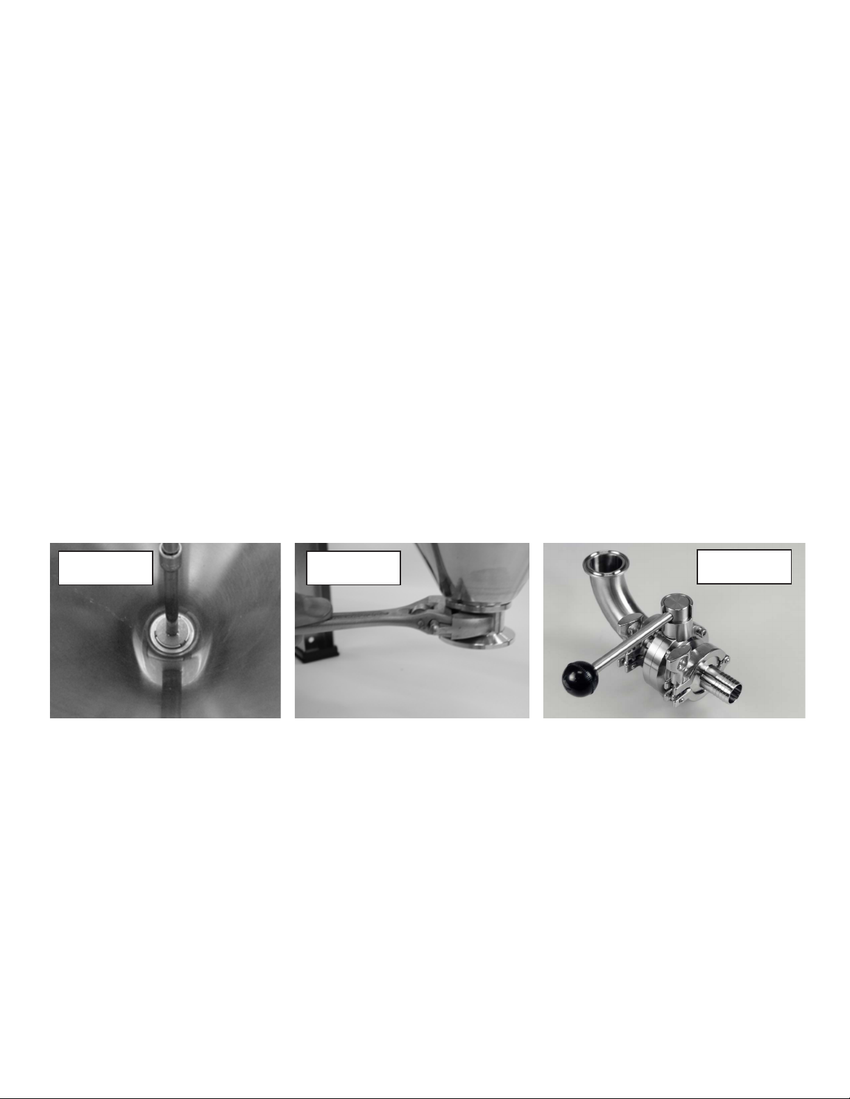
Bottom Dump
Install the weldless sanitary bulkhead into the bottom of the cone as shown in Figure 1a and 1b. Place the bulkhead nut into the hole in
the bottom of the tank. Install the large o-ring in the groove of the tri-clamp bulkhead and thread it on the bulkhead nut by hand. Install
the sanitary bulkhead tool on the end of a long 3/8”extension bar and a ratchet wrench (not included). Using an open end wrench (not
included) turn the tri-clamp fitting while holding the nut stationary with the ratchet wrench until the fitting is tight. Dipping the parts in
sanitizer just before assembly helps lubricate the o-ring joint and makes tightening easier.
Assemble the bottom dump assembly as shown in Figure 2 using a 1”gasket between each flange. Orient the clamps and valve as
shown so that they clear the floor and tank and do not interfere with the rotation of the valve handle. Be sure the handle of the valve
faces up, and that the handle rotates outward. Then attach the assembly onto the tank, again using a 1”gasket.
If you are using the optional leg extensions, it is not necessary to use the elbow, and this will allow the trub and yeast to flow more freely.
Simply install the valve directly on to the bottom dump fitting. You’ll be pressure testing all the fittings during the sanitation process, so if
a leak is present you’ll be able to tighten it then.
ASSEMBLY
FIGURE 1a FIGURE 1b FIGURE 2

4
Fermenator™V2 © Blichmann Engineering, LLC 2019
For replacement parts, visit: blichmannengineering.com/genuine-replacement-parts
Aseptic Valve and Rotating Racking Arm
Install a small o-ring into the groove of the flare fitting on the aseptic valve as shown in Figure 3. Install the 2 QuickConnect™ caps onto
the ends of the aseptic valve. Insert the assembly into the hole in the conical side of the tank (see Figure 4). Place the flare fitting nut on
the racking tube and thread onto the flare fitting. Tighten the flare nut snugly with a wrench – do not over-tighten or you could
inadvertently bend the tank while tightening. It is not necessary to excessively tighten the fitting to get a good seal. If your wrench it too
thick to fit between the tank and the clamp on the racking assembly, install the racking fitting first, and then clamp the valve to it after
tightening.
Install the tube as directed by the side of the aseptic valve shown in Figure 5. This will allow you to use the handle as a guide to
determine the position of the racking arm when draining the beer or wine. The racking arm should initially be positioned horizontally
(below right).
FIGURE 3 FIGURE 4 FIGURE 5
TIP: The only time it is necessary to rotate the racking arm is for the final racking of the finished beer. Limiting the rotation of the racking
arm will reduce any possibility of a leak.
Lid Assembly
Place the U-shaped lid seal over the edge of the lid (not on the tank) with the small bead on the seal facing toward the lip of the tank as in
Figure 6. Place the lid on the tank and orient the hatch and airlock holes to your desired location. Be sure the lid is centered on the tank
as much as possible. Place the V-band clamp around the lid and tank lip and start the T-nut on the clamp stud as in Figure 7. The V-band
clamp can be installed with either side up and with the clamp in any orientation. Note that the unit is shipped with a plain nut installed
on the V-band to prevent shipping damage – it can be removed and discarded. Initially tighten the clamp to about 1/2”(13mm) of gap
between the band segments (Figure 8), then, using a rubber or wood mallet, gently tap the outside perimeter of the V-band clamp to
seat the clamp firmly and evenly all the way around the lid seal. Start at the opposite side of the T-handle and work your way around to
the handle. Retighten the clamp so the segment gap is less than 3/8”(13mm).
NOTE: ALWAYS apply a dab ofVaseline or drop of oil on the threads of the draw bolt before each use to prevent wear and galling of the
threads. Galled or warn threads are NOT covered under warranty.
FIGURE 6
Bead
WARNING: Failure to correctly install and tighten the lid clamp can cause the lid to blow off during pressurization
resulting in serious injury or death! Please contact your Authorized Fermenator™Distributor or Blichmann Engineering™
(www.BlichmannEngineering.com) if you have any questions about proper assembly. Do not operate the unit until
you are certain that you understand the proper installation procedure.
FIGURE 7
FIGURE 8
3/8”(13mm) Max Gap
5
Fermenator™V2 © Blichmann Engineering, LLC 2019
For replacement parts, visit: blichmannengineering.com/genuine-replacement-parts
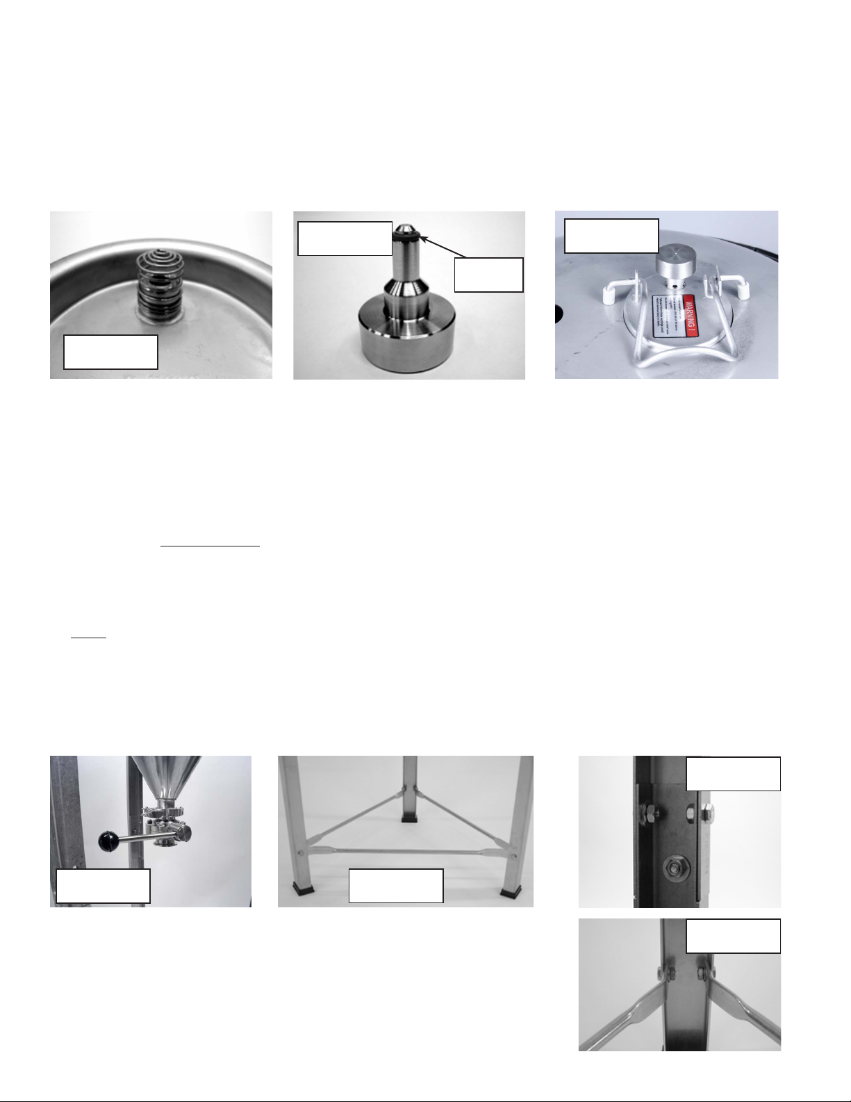
Lid Hatch
Install the pressure relief valve filter spring on the inside of the lid hatch as shown in Figure 9. The purpose of this filter is to keep particles
from clogging the relief valve, which may lead to a dangerous over-pressurization of the tank. Install lid in the oval hole in the lid
(Figure 10). Place the small orange o-ring on the pressure relief valve piston (Figure 10) and place it in the small hole in the lid as shown
in the photo to the right (bottom). The weight of the piston will limit the pressure in the unit to 3 PSI.
WARNING: Read the“Operation Section”prior to use to prevent over pressurization of the fermentor!! It is critical that the pressure relief
valve filter spring be installed on the lid to help prevent foreign material from clogging the pressure relief valve opening.
FIGURE 9
FIGURE 10 FIGURE 11
Carry Handles
The folding carry handles have been preinstalled on your fermentor. However, they have been tightened so they do not rotate in
shipment and become damaged. Using two 7/16”wrenches, loosen the nylock nut so the handle moves freely. However, be sure
the nut is still fully engaged on the bolt. The 7 gallon and 14.5 gallon models can be moved when full, but be sure to use 2 people to
carry the 14.5 gallon model.
WARNING: The 27 gallon model is too heavy to move when full. DO NOT attempt to move this unit when full. The carry handles are
provided to move it only when empty.
Optional Leg Extension Kits – F3-7, F3-14, and F3-27 models (For F3-42 see supplemental manual provided with that product)
Assemble the legs and braces as shown in Figure 12, through Figure 14 using the ¼-20 hardware provided. Note that the braces go on
the inside of the leg. The washers also go on the inside of the leg as shown in Fig 13 and Fig 14. It is recommended that you install all of
the hardware finger tight first, and tighten the assembly when all fasteners are in place. This will allow slight adjustments of position as
needed for ease of assembly. The leg extensions allow for gravity draining into a keg or bottling bucket.
NOTE: It is not necessary to install the 90 degree street elbow on the bottom dump assembly when using the leg extension kit (Figure
11). This will allow the trub and yeast to flow more freely from the dump valve.
O-Ring
FIGURE 11 FIGURE 12
FIGURE 13
FIGURE 14
Table of contents
Other Blichmann Industrial Equipment manuals


