Ortlieb Tool-Grip-HSK Guide

Version 02.08.2019
Technical Documentation
Tool-Grip®-HSK
Tool grippers for Hollow Taper Interface
DIN 69893 / DIN 69063 / ISO 12164-1 + ISO 12164-2

2
Ortlieb Präzisionssysteme GmbH & Co. KG • Jurastr.11 • 73119 Zell unter Aichelberg • Germany

Ortlieb Präzisionssysteme GmbH & Co. KG • Jurastr.11 • 73119 Zell unter Aichelberg • Germany
3
Content:
1
General ..................................................................................................................................4
1.1
Introduction.....................................................................................................................4
1.2
Guarantee ......................................................................................................................5
1.3
Intended Use ..................................................................................................................6
1.4
Initial start-up..................................................................................................................6
2
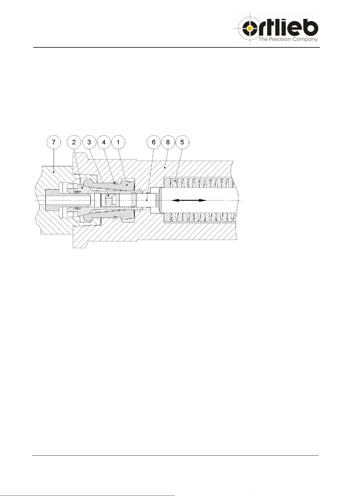
Product-description ................................................................................................................7
2.1
Tool-Grip
®
Standard .......................................................................................................8
2.2
Tool-Grip
®
Repair-kit.......................................................................................................8
2.3
Tool-Grip
®
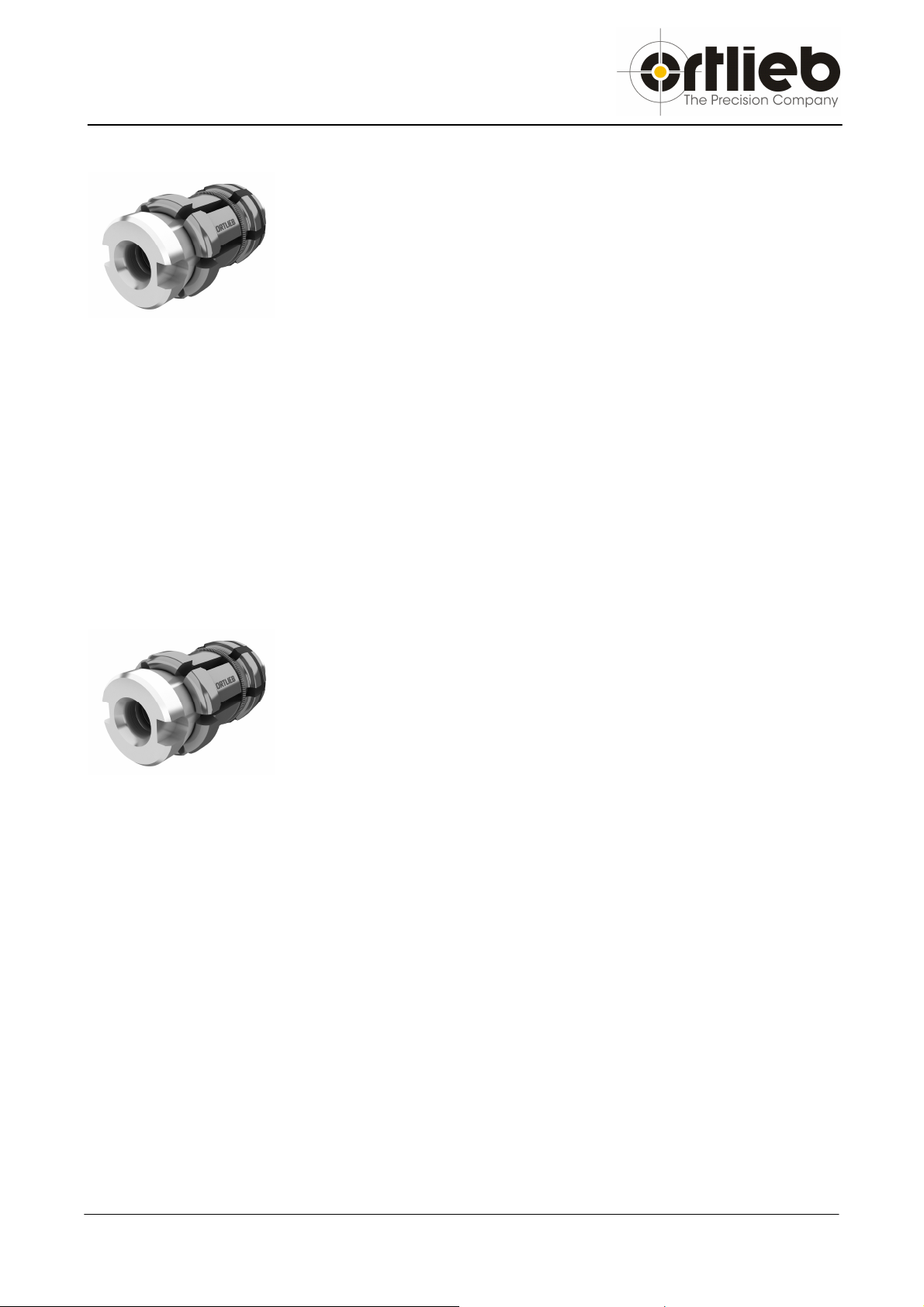
Maintenance-free ..........................................................................................9
2.4
Tool-Grip
®
with holding function....................................................................................10
3
Accessories..........................................................................................................................11
3.1
Technical data ..............................................................................................................11
3.2
Spare parts...................................................................................................................11
4
Mounting instruction .............................................................................................................12
5
General Safety Instructions ..................................................................................................14
5.1
Checklist for Installation................................................................................................16
5.2
Troubleshooting............................................................................................................18
6
Assembly declaration ...........................................................................................................19
7
Shipping data .......................................................................................................................20

1. General
4
Ortlieb Präzisionssysteme GmbH & Co. KG • Jurastr.11 • 73119 Zell unter Aichelberg • Germany
1 General
1.1 Introduction
This operation instruction will help you to operate your Ortlieb product safely and to avoid
accidents, possible dangers and risks.
Please read this operation instruction and the safety instructions carefully before initial start-up.
This documentation provides all information on operating and maintaining your Ortlieb product.
Ortlieb Präzisionssysteme GmbH & Co. KG assumes no liability for damages and interruptions
caused by disregarding several articles of this documentation.
Ortlieb Präzisionssysteme GmbH & Co. KG reserves the right to make any technical changes and
improvements to this product. No liability on literal mistakes.
For Start-up, operation and maintenance, the information in this manual must be supplemented by
the relevant national and international „safety and accident prevention regulations“. Compliance
with the safety regulations and statutes will prevent injury and damages to machinery and this
product.

1. General
Ortlieb Präzisionssysteme GmbH & Co. KG • Jurastr.11 • 73119 Zell unter Aichelberg • Germany
5
1.2 Guarantee
Products of Ortlieb Präzisionssysteme GmbH & Co. KG are produced according to national and
international standards as well as company standards, supervised by a certified quality assurance.
For those products Ortlieb Präzisionssysteme GmbH & Co. KG assumes liability in the manner that
parts with material or production defects proven within 12 month after purchasing were repaired
free-of-charge, replaced by new ones or taken back to the charged price.
In the event of improper assembly and operation, use of non-original spare parts, unauthorized
modifications to our product we shall assume no liability for personal injury or damage to
machinery and our product.
We shall assume no liability for damage of any type resulting from the removal of safety devices.
We take the initial start-up of our products on appropriate and technically flawless machines by
qualified and continuous trained personal for granted.

1. General
6
Ortlieb Präzisionssysteme GmbH & Co. KG • Jurastr.11 • 73119 Zell unter Aichelberg • Germany
1.3 Intended Use
Use the tool-grippers only for the intended use. Insufficiently clamped tools or work-pieces, failure
to comply „safety and accident prevention regulations“, and the use of work-pieces and our
products on machines that are not intended for this propose, can result in personal injury and
damages to the clamping devices. In this case, we shall assume no liability. Do not apply force
during assembly, disassembly and operation; this could damage the clamping device or the
machine.
1.4 Initial start-up
A function check is implicitly before initial operation of the tool-gripper. To ensure a safe and
precise operation of the tool-gripper during machining, a sufficient clamping force must be
provided. Check the clamping force.
See Checklist for Installation p.16
The tool-gripper, especially the function surfaces must be clean and lubricated sufficiently. It is
strongly recommended to grease with “lubricant metal (Metaflux)” (special grease).
METAFLUX-lubricant metal paste Nr. 70-8508
Pay attention:
Mixture with other greases is not allowed!
Techno-Service GmbH (Metaflux-Dealer),
Detmolderstr. 515; 33605 Bielefeld, Germany
Phone: +49 (0) 521/92444-0, Fax: +49 (0) 521/207432
Never exceed the axial and radial forces specified on the tool-gripper. Check the clamping force
regularly!

2. Product-description
Ortlieb Präzisionssysteme GmbH & Co. KG • Jurastr.11 • 73119 Zell unter Aichelberg • Germany
7
2 Product-description
The Ortlieb Tool-Gripper distinguishes by a simple outline in the spindle and compact dimensions.
The rubber-bonded clamping segments are designed for maximum clamping force and high
revolutions, especially for HSC-machining and are rated for a life time of 2 mio. load alternations.
The large central cooling feed provides a secure cooling when using coolant lubricant or MQL
(minimal quantity lubrication).
Pos.
Description
1 Segments
2 Draw-bolt
3 Pin
4 Ring spring
5 Disk springs
6 Drawbar
7 Tool
8 Spindle
Function:
Milling spindles on machine tools are usually fitted with conventional spring loaded tool clamping
systems. The tool-gripper operates on pulling force.
The six rubber-bonded clamping segments were spread equally by the taper on the draw-bolt and
draw-in the tool-holder by the 30°-shoulder into the taper of the machine spindle. During clamping,
25% of the clamping force is dispensed upon the taper, 75% upon the front surface. Thus, also
with high machining forces it is granted, that the tool never lifts from the front surface.
To change the tool, the disk springs were compressed, usually by a hydraulic cylinder. The draw-
bolt is pushed by the drawbar to the front, releases the clamping segments and pushes the tool by
force out of the spindle taper. The ring spring provides a closing of the clamping segments which
release the tool for changing.

2. Product-description
8
Ortlieb Präzisionssysteme GmbH & Co. KG • Jurastr.11 • 73119 Zell unter Aichelberg • Germany
2.1 Tool-Grip
®
Standard
The Standard-Tool-gripper for high clamping forces and high
revolutions with large central cooling feed. Maintenance friendly
and persistent.
By its simple design and few components, this tool-gripper is mounted quickly, extreme
maintenance friendly and persistent.
Your benefit:
- Designed for high clamping force and high revolutions (Technical p.11)
- Large central cooling feed for cooling lubricant or MQL
- Maintenance friendly and persistent
2.2 Tool-Grip
®
Repair-kit
The repair-kit tool-gripper allows to restore and rework worn
spindles by regrinding the taper and the front plane surface.
Designed especially for spindle-services and the rework of used spindles. Worn spindles were re-
grinded on the front plane surface and the taper. This repair-kit allows to double the life time of
spindles without the loss of clamping force or accuracy which safes money for expensive spare
parts.
Your benefit:
- Cost efficient: Allows rework and regrinding the machine spindle
- Easy replacement of the tool-gripper
- Available in standard version, maintenance-free or with holding function

2. Product-description
Ortlieb Präzisionssysteme GmbH & Co. KG • Jurastr.11 • 73119 Zell unter Aichelberg • Germany
9
2.3 Tool-Grip
®
Maintenance-free
The version with ceramics on the draw-bolt is complete
maintenance-free up to 3 mio. load alternations with constant
clamping-force. Afterwards, just the clamping segments have to be
replaced. The draw-bolt can be reused.
Function:
The incomparable sliding properties and wear-resistance of the steel-ceramics combination is
undisputable since the introduction of the hybrid-bearing. Ortlieb offers those advantages for the
first time ever for tool-grippers.
Insiders are aware of the problems of constant decreasing clamping force caused by a lack of
maintenance. As long as the maintenance instructions are kept, constant clamping force is
guaranteed over the total life time. Reality shows that regular maintenance and re-greasing is not
accomplished with the required care. Result: the clamping force decreases rapidly and the life-time
of the clamping system is extremely shortened (black line).
After initial lubrication, the tool-gripper with ceramics stands 3 million load alternations with
constant clamping force without maintenance. (red line)
Your benefit:
- After initial lubrication maintenance-free up to 3 mio. load alternations with constant
clamping force
- Available as standard, repair-kit and with holding function

2. Product-description
10
Ortlieb Präzisionssysteme GmbH & Co. KG • Jurastr.11 • 73119 Zell unter Aichelberg • Germany
2.4 Tool-Grip
®
with holding function
These tool-grippers are especially designed for even faster
changeovers. The already released tool is held safely in the spindle
with a defined force till the tool changer pulls the tool out of the
spindle.
Function:
By replacing the standard tool-gripper by a tool-gripper with holding function (p.11) faster
changeovers are possible.
Connection dimensions and the stroke are the same to the standard version. During the release of
the draw-bolt pushes the tool-holder 0.2 +0,2 mm out of the taper of the spindle. The tool-holder is
held on the 30° shoulder by clamping segments with small slots in a distance of 0,5 - 0,6mm to the
front plane surface of the spindle. When the tool-holder is pulled out by the tool-changer, the
clamping segments with the slots act as a spring with adjustable holding force. When the tool-
changer pushes a tool-holder in the spindle, the clamping segments were compressed and hold
the tool-holder on the 30°-shoulder in a distance of 0,5 - 0,6 mm to the front plane surface of the
spindle.
Your benefit:
- Faster changeovers due to holding function
- Simply replace the standard tool-gripper with same installation dimensions
- Tool-grippers with different holding forces on demand
Technical advices:
- Blow-out air: Force which occurs by blow-out air has to be lower than the holding force
- Tool-weight: Limiting the tool weight is strongly recommended
- Release velocity: To ensure a safe tool-holding, decreasing of the release velocity can be
necessary.

3. Accessories
Ortlieb Präzisionssysteme GmbH & Co. KG • Jurastr.11 • 73119 Zell unter Aichelberg • Germany
11
3 Accessories
3.1 Technical data
S
ize
Type
Fz max
Fsp max
rpm
stroke
Nm*
HSK-A 25 / B 32 TG 19-06 1,5 kN 4,5 kN 80000 1/min
4,6 7 Nm
HSK-A 32 / B 40 TG 24-06 2,0 kN 6,0 kN 60000 1/min
6,0 14 Nm
HSK-A 40 / B 50 TG 30-06 4,0 kN 12,0 kN 45000 1/min
5,7 25 Nm
HSK-A 50 / B 63 TG 38-06 8,0 kN 24,0 kN 40000 1/min
6,0 50 Nm
HSK-A 63 / B 80 TG 48-06 10,0 kN 30,0 kN 30000 1/min
6,0 100 Nm
HSK-A 80 / B100 TG 60-06 15,0 kN 45,0 kN 25000 1/min
6,9 200 Nm
HSK-A 100 / B125
TG 75-06 24,0 kN 60,0 kN 15000 1/min
7,6 365 Nm
HSK-A 125 / B160
TG 95-06 35,0 kN 105,0 kN 12000 1/min
10,0 710 Nm
HSK-A 160 TG 120 40,0 kN 120,0 kN 10000 1/min
10,5 1435 Nm
* transferable torque without driving dog (Form E)
**Further technical data and installation dimensions on demand
3.2 Spare parts
S
ize
Tool
-
gripper
TGR
-
TGZ
Mounting devices
(complete)
segments draw-bolt
for segments for draw-bolts
Standard-version
HSK-A 25 / B 32 TG 19-06 TGR 19-06 TGZ 19 TGM 19 -
HSK-A 32 / B 40 TG 24-06 TGR 24-06 TGZ 24 TGM 24 TGS 24
HSK-A 40 / B 50 TG 30-06 TGR 30-06 TGZ 30 TGM 30 TGS 30
HSK-A 50 / B 63 TG 38-06 TGR 38-06 TGZ 38 TGM 38 TGS 38
HSK-A 63 / B 80 TG 48-06 TGR 48-06 TGZ 48 TGM 48 TGS 48
HSK-A 80 / B100 TG 60-06 TGR 60-06 TGZ 60 TGM 60 TGS 60
HSK-A 100 / B125 TG 75-06 TGR 75-06 TGZ 75 TGM 75 TGS 75
HSK-A 125 / B160 TG 95-06 TGR 95-06 TGZ 95 TGM 95 TGS 95
HSK-A 160 TG 120 TGR 120 TGZ 120
TGM 120 TGS 120
* All sizes hard coated on request
** Other designs on request
Holding version
HSK
-
A 40 / B 50
TG 30
-
66
TGR 30
-
66
TGZ 30
TGM 30
TGS 30
HSK-A 50 / B 63 TG 38-66 TGR 38-66 TGZ 38 TGM 38 TGS 38
HSK-A 63 / B 80 TG 48-66 TGR 48-66 TGZ 48 TGM 48 TGS 48
HSK-A 100 / B125 TG 75-66 TGR 75-66 TGZ 75 TGM 75 TGS 75
Maintenance-free
HSK
-
A 50 / B 63
TGC 38
TGRB 38
-
06
TGCZ 38
TGM 38
TGS 38
HSK-A 63 / B 80 TGC 48 TGRB 48-06
TGCZ 48
TGM 48 TGS 48
HSK-A 100 / B125 TGC 75 TGRB 75-06
TGCZ 75
TGM 75 TGS 75

4. Mounting instruction
12
Ortlieb Präzisionssysteme GmbH & Co. KG • Jurastr.11 • 73119 Zell unter Aichelberg • Germany
4 Mounting instruction
Mounting devices:
•
Mounting device TGM to mount clamping segment TGR
•Installation wrench TGS to mount the draw-bolt TGZ
•torque wrench, heagon-wrench
•depth gauge
Pay attention:
Mounting devices are only suitable for one size.
Each size needs its own mounting devices.
1. Setting of rubber-bonded clamping segments TGR
•Take out the draw-bolt TGZ.
•Drive drawbar in clamping position. (without tool)
•Release the clamp screw of the TGM mounting device.
•Insert rubber-bonded segments TGR in the sleeve (see drawing).
•The vulcanized end of the clamping segment is compressed down by tightening the clamp
screw.
(In case a drawbar is mounted, make sure TGR fingers are closed down to thread dia.)
•Insert TGM and TGR into the HSK-Spindle.
•Release the spanner screw. The TGR automatically stays at its place in the spindle recess.
•Take off the mounting device.
•Function-surfaces must be lubricated!
Lösestellung
Spannstellung

4. Mounting instruction
Ortlieb Präzisionssysteme GmbH & Co. KG • Jurastr.11 • 73119 Zell unter Aichelberg • Germany
13
2. Setting of draw-bolt TGZ
•Drive drawbar in release position.
•Screw draw-bolt on the drawbar.
•Adjust the position of the draw-bolt according the set-up measure (EM) shown in the
drawing of the tool-gripper. Tighten the set screw against the draw-bar.
•Mount installation wrench TGS to a torque wrench and adjust the demanded torque.
•Insert the pins of the installation wrench TGS into the notches of the draw-bolt TGZ.
•Tighten with demanded torque. Do not exceed the maximum torque.
pins
notch
•Check set-up measurement!
•Check clamping force
Disassembly:
•Remove the draw-bolt TGZ from the tool-gripper.
•Insert TGM into the HSK-Spindle. Front plane surfaces must match.
•Compress rubber-bonded clamping segments by tighten the spanner screw. The draw-bar
can stay in the spindle. Remove TGM and TGR
•Do not apply force during compressing the clamping segment to prevent damages.

5. General Safety Instructions
14
Ortlieb Präzisionssysteme GmbH & Co. KG • Jurastr.11 • 73119 Zell unter Aichelberg • Germany
5 General Safety Instructions
1. Safety requirements to machines
-Do not rotate the spindle without a clamped tool.
-On a breakdown of the clamping power – unless not clamped by a laminated disc spring – a
signal must stop the machine spindle and the tool has to be clamped till a complete stop of the
spindle.
-After a power breakdown and on return of the power, a changing over must not occur.
-During operation, the spindle and the clamped tool must be secured by a safety facility.
-The opening of the safety doors is only possible if the machine spindle stands still.
-All operations and maintenance to the spindle and the tool-gripper are only allowed if the
spindle stands still.
2. Operation cylinders, machine spindles
To operate the tool-grippers, please use only appropriate cylinders according the safety and
accident preventions regulations. Mounting the tool-gripper to a spindle with an existing operating
cylinder, make sure that the release power is sufficient to release the tool from the spindle and the
maximum clamping force is not exceeded! The drawbar and the laminated disc springs must be
designed to endurance strength. Set and check the limit switch to check the stroke before initial
operations. The clamping segments might get damaged.
3. Operating data
The allowed operating data, maximum clamping force and maximum revolutions shown on the
technical data sheet (p. 11) may not be exceeded. The minimum clamping force depends on
cutting rates.see DIN 69893 / DIN 69063
4. Tools
Please use solely suitable tools according DIN 69893 / DIN 69063, matching your machine
(see Technical data page 11).

5. General Safety Instructions
Ortlieb Präzisionssysteme GmbH & Co. KG • Jurastr.11 • 73119 Zell unter Aichelberg • Germany
15
5. Residual risks
The system machine tool – tool-gripper – tool holder is mainly influenced by the properties of the
tool (shape, weight, unbalance, material, etc.) as well as the cutting parameters which can cause
residual risks. Those remaining dangers must be considered by the worker and eliminated by
appropriate means.
6. Maintenance
Accurate and regularly maintenance (quarter annually) increases the natural life of the tool-gripper.
Please keep the following advices.
-Check set-up measurement and the tightening of the draw-bolt regularly.
-Check clamping force
-Clean the tool-gripper regularly according the operation conditions from swarf and cooling
lubricant. Dirt reduces the runout accuracy and reduces the clamping force.
-Do not use polar or ester-containing solvents to clean the spindle and the tool-gripper. Sealings
and the rubber-bonded parts could be damaged.
-Avoid cleaning with compressed-air gun.
-Re-grease the tool-gripper at least after 200.000 load alternations. Sufficient lubrication
increases the clamping force and reduces wear.
METAFLUX-lubricant metal paste Nr. 70-8508
Pay attention:
Mixture with other greases is not allowed!
Techno-Service GmbH (Metaflux-Dealer),
Detmolderstr. 515; 33605 Bielefeld, Germany
Phone: +49 (0) 521/92444-0, Fax: +49 (0) 521/207432
-Check the tool-gripper for cracks and other damages. After a crash, a complete check is
essential. You will find spare parts on page 11.
-Replace damaged parts only by original spare-parts. Otherwise guarantee is expired.
The alternative: Use the maintenance-free tool-gripper with ceramics!
Please contact us!

5. General Safety Instructions
16
Ortlieb Präzisionssysteme GmbH & Co. KG • Jurastr.11 • 73119 Zell unter Aichelberg • Germany
5.1 Checklist for Installation
(Rubber Clamping Segment TGR + draw-bolt TGZ)
1.) TGR and TGZ are grounded and paired in the testing facility. TGR + TGZ are not
individually interchangeable. This guarantees stroke position ±0.1 mm when TG is
exchanged.
2.) Tool –“Eject” max. 0.5 mm (0.3mm up to TG30). The tool is only drawn in securely by the
tool gripper TG in this range. Ensure that the clamping reserve is min. 2 mm and max. 3
mm.
3.) Check the clamping force. The max. pull-in force, Fz max. , must not be exceeded.
4.) Tool clamping must not be one-sided. Guide the disc spring stack accurately.
5.) Spindle receiver must meet DIN 69063 standard and Ortlieb TG installation dimensions.
Taper pre-load 0.1-0.4 mm, depending on size.
(Distance between spindle and tool plane surfaces).
Functional surfaces hardened min. 1mm deep to HRc 60 +2.
6.) When clamping the tool, there must not be any pressure (blow-out) present before the
taper pre-load. Otherwise the tool may not be able to be moved into the end position.
TGR would sustain damage.
7.) Observe the control operation.
Insert the tool until it reaches the limit stop at the TGZ plane surface, then clamp it.
Clamping must not de done too soon, as otherwise the TGR can not pull-in the tool.
8.) Tool change: Gripper – eject – unclamp - blow-out. Make sure that the tool and spindle
are clean. If chips are drawn in, TGR will sustain damage. (One-sided overloading of the
TGR clamping segments).
9.) If one TGR- segment breaks, the tool will nevertheless be clamped safely. However the
TG (TGR + TGZ ) must be exchanged immediately as a complete unit.

5. General Safety Instructions
Ortlieb Präzisionssysteme GmbH & Co. KG • Jurastr.11 • 73119 Zell unter Aichelberg • Germany
17
10.) The tool gripper is a part which is subject to wear. Under favourable operation conditions,
the complete tool gripper must be exchanged every 2x10
6
load alternations. We do not
assume liability and guarantee on consequential damages in case only parts (TGR +
TGZ) are exchanged).
11.) Refer to the installation instructions for information about how to change the TG. Before
installing the TG, check the spindle for damage. Grease the functional surfaces.
12.) For optimal drawing-in force, RPM
max.
and n
max.
, please refer to WLZ RWTH Aachen:
Richtlinie zur Grenzbelastbarkeit HSK-Schnittstelle (Project Jan. 2003)
13.) Tools must meet DIN 69893 standards. After usage, please check that the cooling
lubricant supply tube in the tool is tightened. If it gets loose, the tool cannot be pulled-in
properly!
14.) Without an HSK tool insert, there is no operation of the spindle allowed.
(Out-of-balance caused by TGR + TGZ)
15.) After every crash, the TGR and TGZ must always be exchanged completely.
16.) The clamping force transmitted to the HSK by the tool gripper TG should not be below the
standard values specified in DIN 69063 / DIN 69893. It is also important that the
functional surfaces and the clamping system are greased regularly (with ball bearing or
assembly grease.)
Based on experience, re-greasing should be done after every 200.000 load alternations
at the least in order to keep the clamping force as uniform as possible. Regular
measurement of the clamping force, either quarterly or semi-annual, will ensure the
required safety for the work process.
17.) Check the tightening of the draw-bolt TGZ and the drawbar regularly to ensure a proper
function of the tool-gripper.
A loose draw-bolt causes a loss of clamping force and ejects the tool far over the allowed
max. 0,5mm.

5. General Safety Instructions
18
Ortlieb Präzisionssysteme GmbH & Co. KG • Jurastr.11 • 73119 Zell unter Aichelberg • Germany
5.2 Troubleshooting
Below, you will find some of the most frequently asked questions. If an error cannot be eliminated
with the methodes below, please contact your technical support team. Always name the accurate
article-number and the description in case of questions or re-order.
Problem
Possible cause
Remedy
Low clamping force Set-up measurement of
the draw-bolt does not
match
Check set-up measurement according the
installation drawing. Re-tighten the draw-bolt
if necessary
Tool-gripper is lubricated
insufficiently
Re-grease tool-gripper according greasing
instructions
Wear of the segments Check clamping segments on wear
Damage of the disk spring
stack
Disassemble the tool-gripper and check
pulling-force on the drawbar
Low pulling-power of the
cylinder / disk-springs
Too high clamping
force
Set-up measurement of
the draw-bolt does not
match
Check set-up measurement according the
installation drawing. Re-tighten the draw-bolt
if necessary
high pulling-power of the
cylinder / disk-springs
Disassemble the tool-gripper and check
pulling-force on the drawbar
Bad run-out
accuracy on the tool
/ tool-holder
Dirt at the front plane
surface or in the HSK-
taper
Eject the tool-holder; clean the HSK-taper in
the spindle and the tool-gripper
Damaged tool-holder Dimensional check of tool-holder, change
tool-holder if necessary
No proper ejection of
the tool-holder
Set-up measurement or
stroke does not match
Check set-up measurement and stroke
Inner outline does not
match DIN 69893
Check inner outline of the tool holder;
Especially l
6
acc. DIN 69893
Damaged clamping
segments
In emergency: cut tool-holder with an angle
grinder and change tool-gripper
Tool-holder is not
clamped or pulled-in
properly
Distance between tool-
holder and spindle is too
big
Check set-up measurement, adjust the tool-
changer, especially if the spindle is re-grinded
and reworked
Coolant feed tube is bend Check coolant feed tube, replace if necessary

6. Assembly declaration
Ortlieb Präzisionssysteme GmbH & Co. KG • Jurastr.11 • 73119 Zell unter Aichelberg • Germany
19
6 Assembly declaration
for an incomplete machine (acc. machine directive 2006/42/EG)
Name of the company and producer:
Ortlieb Präzisionssysteme GmbH & Co. KG
Jurastr.11
73119 Zell unter Aichelberg
E-Mail: info@ortlieb.net
The Tool-Grip
®
HSK-Tool-gripper is described as an incomplete machine according article 2g of
the machine directive and designated only to be mounted into or with an other machine or
equipment.
The following fundamental safety and health-protection requirements according attachment 1 of
the machine directive were used, are valid and adhered:
Nr. 1.1.3, Nr. 1.3.2, Nr. 1.5.4, Nr. 1.6.1
The following standards (or extracts of these standards) are used:
DIN 69893, DIN 69063,
The start-up of this product is forbidden until it is proven, that the machine in which the above
named incomplete machine is mounted to conforms the regulations according the machine
directive 2006/42/EG.
The special technical documentations according attachment VII part B have been complied. The
producer obligates to provide these documentations in written form to public authorities if their
request is justified.
Only the management of Ortlieb Präzisionssysteme GmbH & Co. KG, represented by
Mr. Dirk Laubengeiger, is authorized to comply the relevant technical documents according
attachment VIII B to this product
Zell unter Aichelberg,

7. Shipping data
20
Ortlieb Präzisionssysteme GmbH & Co. KG • Jurastr.11 • 73119 Zell unter Aichelberg • Germany
7 Shipping data
Article-No.: ............................................................................................................
Serial No.: ............................................................................................................
Delivery date: ............................................................................................................
Table of contents
Other Ortlieb Tools manuals