54
2. Handling the
wheelchair
2.1 Use
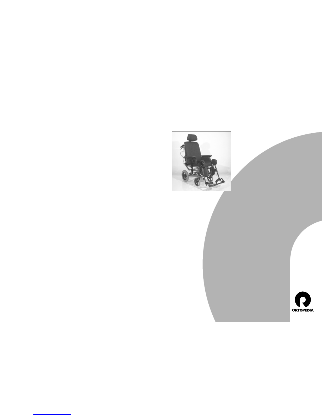
The
THERAPY WHEELCHAIR VARIUS
is de-
signed for at home or geriatric provi-
sioning.
Besides the upholstered seat and an
angle adjustable, upholstered backrest
the
VARIUS
possesses a seat depth ad-
justment as well as infinitely cant adjust-
ment from -4° (as an aid for rising) to
20° seat inclination.
The
VARIUS
is designed for the daily use
indoors and outdoors.
Before the first use the
THERAPY WHEEL-
CHAIR
should be adapted to you by your
authorised specialist dealer. The driving
experience and physical boundaries of
the user as well as the main field of op-
erations of the
THERAPY WHEELCHAIR
will
be considered during this adaptation.
!Attention:
Always have adaptation and adjust-
ment work carried out by an author-
ised specialist dealer.
1. Foreword
We thank you for the trust that you
placed in our company by choosing a
THERAPY WHEELCHAIR VARIUS
.
The
THERAPY WHEELCHAIR VARIUS
sup-
plies the respectively required adaptations
to your disability with all its equipment
variations and their accessories.
A
THERAPY WHEELCHAIR
is a technical aid,
like any other vehicle. It requires explana-
tion, a little care and holds dangers when
used improperly. The correct handling
must therefore be learned.
This users manual combined with the bro-
chure
safety information for mechanical
wheelchairs
should help you get accus-
tomed to the handling of the
THERAPY
WHEELCHAIR
and prevent accidents.
If need be this users manual as well as the
brochure
safety information for mechani-
cal wheelchairs
are to be read together
with a supervisor or assistant be making
the first drive.
☞Remark:
Please note that the illustrated equip-
ment variants can deviate from your
model.
4.4.2 ERGOpor seat element ........................................................................................ 19
4.4.2.1 Detaching the ERGOpor seat element ............................................... 19
4.4.2.2 Attaching the ERGOpor seat element ................................................ 19
4.4.2.3 ERGOpor-seat cushion ........................................................................ 19
4.5 Seat inclination ................................................................................................................ 20
4.5.1 Adjustment of the seat inclination ....................................................................... 20
4.6 Seat depth ....................................................................................................................... 21
4.6.1 Adjustment of the seat depth .............................................................................. 21
4.7 Angle adjustable backrest (gas spring adjustment) ........................................................ 21
4.8 Height-adjustable sliding handles ................................................................................... 22
4.9 Headrest ........................................................................................................................... 22
4.10 Brake ................................................................................................................................23
4.10.1 Safety information ................................................................................................ 23
4.10.2 Adjustment of the drum brakes ........................................................................... 23
4.10.3 Disengaging the drum brake .............................................................................. 24
4.11 Swivel wheels ................................................................................................................... 24
4.11.1 Tyre equipment ................................................................................................... 24
4.12 Anti-tip castors ................................................................................................................. 24
5. Optional accessories ................................................................................................... 25
5.1 Lateral supports................................................................................................................ 25
5.1.3 Swivelling the lateral support to the rear ........................................................... 25
5.2 Splay wedge .................................................................................................................... 26
5.2.1 Setting the depth ................................................................................................ 26
5.2.2 Setting the height ................................................................................................ 26
5.3 Therapy table ................................................................................................................... 27
5.3.1 Assembly of the therapy table ............................................................................. 27
5.4 Lap belt ............................................................................................................................ 28
5.4.1 Putting on the lap seatbelt with catch ................................................................ 29
5.4.2 Putting on the lap seatbelt with Velcro fastener ................................................. 29
5.4.3 Setting belt length .............................................................................................. 29
6. Care and maintenance ................................................................................................ 30
6.1 Cleaning ........................................................................................................................... 30
6.2 Maintenance .................................................................................................................... 31
6.2.1 Tools ..................................................................................................................... 31
6.2.2 Maintenance instructions ..................................................................................... 32
6.3 Repair ............................................................................................................................... 33
6.4 Customer service .............................................................................................................. 33
6.5 Spare parts ....................................................................................................................... 33
6.6 Disposal ............................................................................................................................ 33
7. Technical data ............................................................................................................. 34
8. Guarantee .................................................................................................................... 35