Ortus Aeonmed VG70 Manual

Aeonmed VG70(E)
UK unboxing and setup instructions
Version1.0

•To provide supplementary guidance (to that in the official manufacturers documentation)
in the unboxingand setup of the VG70(E)
•To provide a mechanism for registering VG70(E) products into the UK Support & Warranty
cover provided by Ortus Medical *
Purpose of this Document
* Registration of product is required for any manufacturer backed support and warranty claims

Box 1 (Smaller)
•VG70(E) ICU Ventilator
•VG70(E)Consumables/Accessories box
•Dimensions (W xDxH) 81 x69 x115cm
•Gross Weight 25kg / Net weight 15kg
Box 2 (Larger)
•VG70(E) Trolley
•Dimensions (W xDxH) 64 x54 x94cm
•Gross Weight 40kg / Net weight 25kg
The VG70(E) UK deliveries are packaged in two boxes:
VG70(E) UK Packaging
1
2

•Within Box 1 is a Packing list and Inspection Certificate.
•Please check off each item delivered from the Packing list
when unboxing.
•Items 23 and 24 are packaged in Box 2.
•For any deliveries with items missing; a copy of the Packing list
and Inspection certificate will be required for warranty claims.
Example Packing list
Example Inspection Certificate
Packing List / Inspection certificate

•Unbox and remove packagingfrom the larger of the two boxes (Box 2) until the trolley as shown in photo 1-A.
•The top of the trolley containsthe ventilatormounting base plate. Unscrew the black locatingscrew from its
transit position in photo 1-B and re-insert from under the trolley base plate as shown in photo 1-C.
•Ensure the threaded screw is flush with the trolley base plate as shown in photo 1-D if this protrudes from the
surface of the base plate, the installation ofthe ventilatoris impossible.
1-A 1-B 1-C 1-D
Assembly Instructions –Step 1 –Trolley Assembly

•Unbox and remove the packaging from the smaller of the two boxes (Box 1) and separate into the three
parts; Ventilatormain unit, ventilatorscreen and the Accessories / Consumables box as shown in photo 2-A.
•Unpack the main ventilatorunit and place this on the trolley prepared in Step 1. Align the two locating pins
on the base of the ventilatorwith the locating holes on the trolley base (photo 2-B).
•Lower the ventilatormain unit onto the trolley base such that its sits level as shown in Photo 2-C. Note that
the front and rear of the unit is not flush at this point.
•Push the ventilatormain unit towards the front of the trolley such that the locatingpins are locked in and
the unit is flush with the trolley as shown in photo 2-D. Then tighten the black locating screw thread as
shown in photo 1-C.
2-A 2-B 2-C 2-D
Assembly Instructions –Step 2 –Main unit attachment to trolley

•Remove the packagingfrom ventilatorscreen and place this on top of the main unit as shown in Photo 3-A.
•Connect the ventilatorscreen display cable to the main unit and using a Philips screwdriver secure the cable
with the small white cable clamp as shown in photo 3-B.
•Locate the ventilatorscreen into the V shaped mounting slot on the main unit such that the screen stands in
its operating position as show in photo 3-C.
3-A 3-B 3-C
Assembly Instructions –Step 3 –Screen Attachment to Main unit

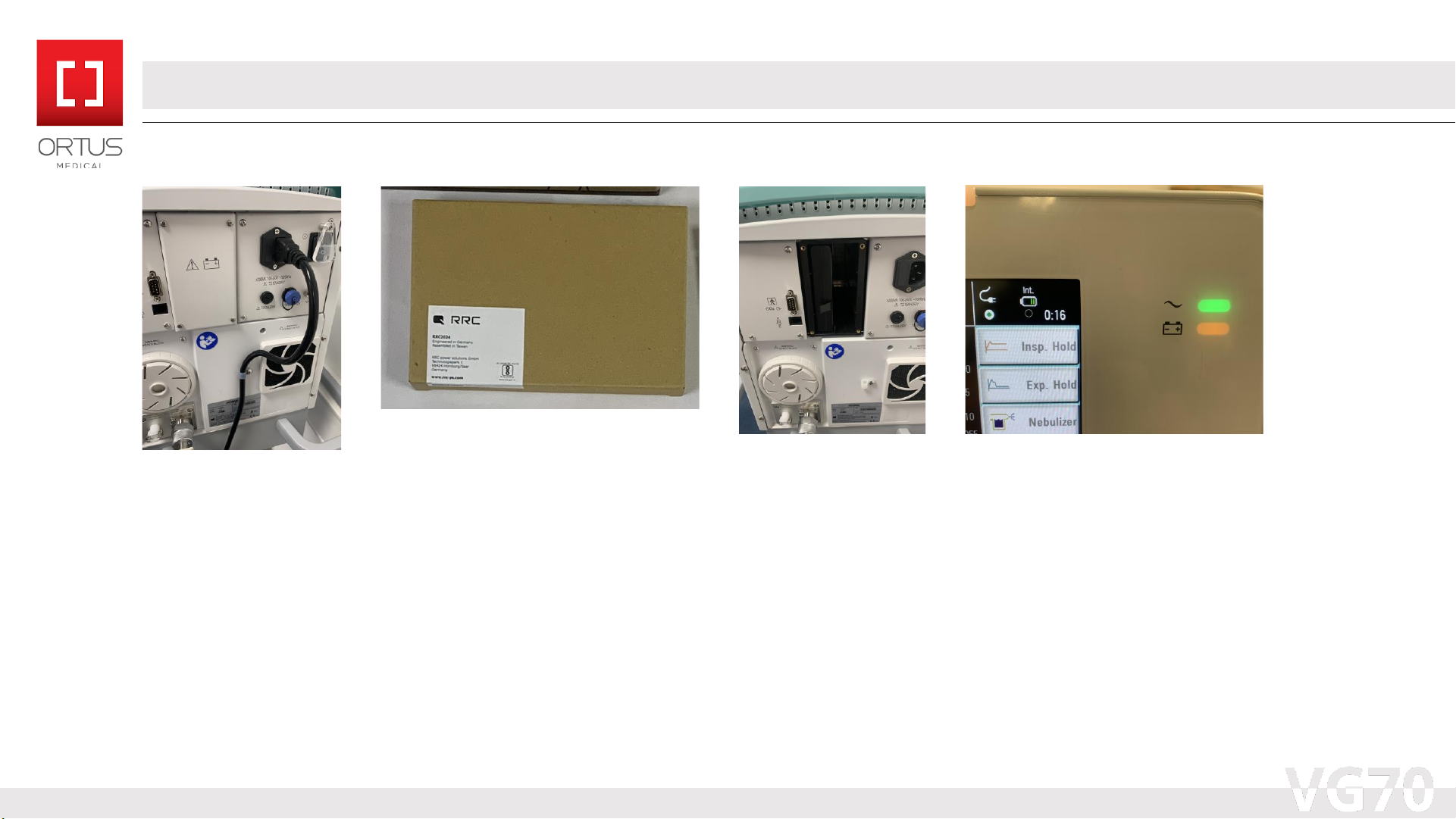
•Rotate the ventilatoron its cart around, such that the rear of the main unit can be accessed and remove the 4
Philips screws holding the battery cover in place (photo 4-A).
•Locate the Battery from the accessories / consumables box, it is packaged in a paperback sized brown box,
remove the battery ready for installation (photo 4-B).
•The Battery can then be inserted into either of the two slots, the photo 4-C shows the battery in the left-hand
slot, but this can be inserted in the right or an additional battery can be installed (not supplied). Once
installed the cover can be re-attached with the screws.
•Once power is applied to the device (latter steps), the battery charging icon and battery status will appear on
the front of the screen (photo 4-D).
4-A 4-B 4-C 4-D
Assembly Instructions –Step 4 –Battery Installation

•Locate the Oxygen Inlet filter from the accessories / consumables box; this is contained in a plastic bag which
should be removed (photo 5-A).
•Install the Oxygen Inlet filter at the rear of the Ventilatormain unit, tightening the threaded connector until
hand tight againstthe oxygen inlet ensuring it is orientated as in photo 5-B.
•Locate the Oxygen supply connection hose from the accessories / consumables box; this is supplied coiled
with tie wraps that should be removed (photo 5-C).
•The Oxygen supply connection hose can now be connected to the Ventilatorand then connected to the local
oxygen source as shown in photo 5-D.
5-A 5-B 5-C 5-D
Assembly Instructions –Step 5 –Hospital Oxygen Connection

•Locate the Two black power cords (1 x UK Mains Plug to IEC female connector and 1 x IEC female to IEC male
connector) from within the accessories / consumables box and remove the cable ties (photo 6-A).
•Connect the UK Mains Plug to IEC female connector to the bottom IEC male connection socket on the trolley
side and the IEC female to IEC male connector to the top IEC female socket as shown in photo 6-B.
•Connect the other end of the IEC male connector to the main ventilatormodule and using a Philips
screwdriver secure the cable with the small white cable clamp as shown in photo 6-C.
•The Unit can then be connected to the UK mains supply and powered on at the wall and on the back of the
main unit behind the clear protective cover (photo 6-D).
6-A 6-B 6-C 6-D
Assembly Instructions –Step 6 –Power Supply Connection

•Included in the accessories / consumables box is a Patient circuit support arm (large brown box) packaged as
shown in photo 7-A, and a small black house mounting bracket also shown in photo 7-A.
•Unpack the Arm from its box and connect the Arm screw thread to the base plateof the Ventilatortrolley as
shown photo 7-B.
•Remove the plasticpackaging from the black hose support bracket and install into the Arm as shown in photo 7-C.
•The fully assembled Arm and hose support bracket should now look like photo 7-D.
7-A 7-B 7-C 7-D
Assembly Instructions –Step 7 –Setup of Arm for Patient Circuits

•The VG70(E) is supplied with a Humidifier to ensure that it can be used out of the box to treat patients (the
supplied configuration should be reviewed by local operatorsas it may lack features depending on intended use).
•The Humidifier included with the ventilatoris supplied in the accessories / consumables box as shown on photos
8-A / 8-B. It can be powered from the trolley using its supplied power cord. Note for alternate Humidifiers power
supply connections may differ.
•To connect the Humidifier to the Trolleypower, remove the metal cover mounting screws with a Philips
screwdriver and install the power connector, then replace the cover as indicated in photo 8-C.
•The humidifier can now be mounted on the trolley as shown in photo 8-D.
8-A 8-B 8-C 8-D
Assembly Instructions –Step 8 –Setup of included Humidifier

•The VG70(E) is supplied with a Reusable Patient circuit to ensure that it can be used out of the box to treat
patients (the supplied configuration should be reviewed by local operators prior to us as it may not meet their
requirements).
•The Patient Circuit, Test lung and CPAP Mask included with the ventilatoris supplied in the accessories /
consumables box and are shown packagedin photos 9-A / 9-B / 9-C.
•The circuit consists of 5 legs and 2 water traps (photo 9-D). Should the user decide to operate the machine
without the humidifier, the double water trap circuit (4 Legs) can be connected directly to the ventilator.
9-A 9-D9-B 9-C
Assembly Instructions –Step 9 –Setup of included Patient Circuit

Annex A –Typical VG70(E) Accessory / Consumables box contents –Key components
1
2
3
4
5
67
8
910
11
12
1. Humidifier
2. Arm for Patient circuit
3. Humidifier Chamber
4. Test Lung
5. Patient Hose Circuit
6. IEC female to IEC male connector
7. UK Mains Plug to IEC female connector
8. Circuit hose support bracket
9. Battery
10. Oxygen Inlet filter
11. Oxygen supply connection hose
12. CPAP Mask

Annex B –Typical VG70(E) Accessory / Consumables box contents –Spares/Additional Items
1. 2 x Spare Breathing Bacterial Filters
2. Nebulizer set with tubing
3. Airway connector
4. Air Inlet Filter element
5. User Manual
6. Circuit hose support bracket (small)
7. Airway connector –right angle
8. 2 x Spare Fuse 3.15A / 250V
9. Oxygen Inlet sintered filter
10. Spare cotton fan filter
11. Spare water trap
12. 2 x spare expiratoryvalve seal
13. Expiratory valueone-way diaphragm
14. Expiratory valve seal removal tool
1234
56
98
7
10 11 12
13
14

Once assembled in order to register the product please
complete the VG70 Acceptance log and email a copy
to medsupport@ortus.co.uk within 30 days
The VG70 Acceptance log (example left) can be
downloaded here: http://www.theortusgroup.com/vg70/
The warranty provided with the VG70 is in line with the
NHS Supply chain terms and conditions.
•Main Ventilator–1 Year.
•Accessory Parts and Spares –3 Months.
•All consumable and wear and tear parts are excluded
from the warranty.
Annex C - Product Acceptance Test Log Completion
This manual suits for next models
1
Table of contents
Popular Medical Equipment manuals by other brands

Arjo
Arjo MaxiSlide Instructions for use

Graham Field
Graham Field John Bunn JB02020 user manual

Omron
Omron Total Power + Heat PM800CAN instruction manual

Wassermann
Wassermann SG-1 user manual

Mobility Research
Mobility Research LiteGait I 360E Operators & service manual

Helicor
Helicor StressEraser quick start guide