Oryx sca3600 Operating instructions


AZ 85284
2
Table of Contents
I. PRELIMINARY STEPS.........................................................................................- 4 -
II. QUICK TROUBLESHOOTING ..............................................................................- 5 -
III. REMOVING TOP COVER AND BACK PANEL..........................................................- 9 -
A. HOW TO REMOVE THE BACK PANEL....................................................................................................... - 9 -
B. HOW TO REMOVE THE TOP COVER ...................................................................................................... - 10 -
IV. PUMP ASSEMBLY REPLACEMENT .....................................................................- 11 -
A. HOW TO REMOVE THE PUMP ASSEMBLY ............................................................................................... - 11 -
B. HOW TO INSTALL THE PUMP ASSEMBLY................................................................................................. - 12 -
V. SENSOR ASSEMBLY REPLACEMENT....................................................................- 13 -
A. HOW TO REMOVE THE SENSOR ASSEMBLY ............................................................................................ - 13 -
B. HOW TO INSTALL THE SENSOR ASSEMBLY .............................................................................................. - 14 -
VI. SPRAY NOZZLE REPLACEMENT .........................................................................- 15 -
A. HOW TO REPLACE THE NOZZLE ........................................................................................................... - 15 -
VII. HEATER ASSEMBLY REPLACEMENT..................................................................- 16 -
A. HOW TO REMOVE THE HEATER ASSEMBLY............................................................................................. - 16 -
B. HOW TO INSTALL THE HEATER ASSEMBLY .............................................................................................. - 18 -
VIII. DISPLAY CONTROL PANEL REPLACEMENT.......................................................- 19 -
A. HOW TO REMOVE THE DISPLAY CONTROL PANEL.................................................................................... - 19 -
B. HOW TO INSTALL THE DISPLAY CONTROL PANEL ..................................................................................... - 20 -
VIIII. PCB ASSEMBLY REPLACEMENT......................................................................- 21 -
A. HOW TO REMOVE THE PCB ASSEMBLY................................................................................................. - 21 -
B. HOW TO INSTALL THE PCB ASSEMBLY .................................................................................................. - 22 -
X. POWER SWITCH REPLACEMENT ........................................................................- 23 -
A. HOW TO REMOVE THE POWER ENTRY MODULE (PEM) SWITCH............................................................... - 23 -
B. HOW TO INSTALL THE POWER ENTRY MODULE (PEM) SWITCH................................................................. - 24 -
XI. FUSE REPLACEMENT ........................................................................................- 25 -
A. HOW TO REPLACE THE FUSES ............................................................................................................. - 25 -

AZ 85284
3
XII. TROUBLESHOOTING STEPS..............................................................................- 26 -
A. PUMP TROUBLESHOOTING................................................................................................................. - 27 -
B. HEATING ELEMENT TROUBLESHOOTING ................................................................................................ - 32 -
C. TEMPERATURE SENSOR TROUBLESHOOTING........................................................................................... - 35 -
D. WATER LEVEL SENSOR TROUBLESHOOTING ........................................................................................... - 36 -
E. NO POWER TO SCA TROUBLESHOOTING............................................................................................... - 37 -
F. NO POWER TO DISPLAY TROUBLESHOOTING........................................................................................... - 41 -
XIII. DOCUMENTATION..........................................................................................- 42 -
A. ERROR CODES ................................................................................................................................. - 42 -
B. SCHEMATICS.................................................................................................................................... - 43 -
C. PCB LAYOUT ................................................................................................................................... - 45 -
D. J6 DISPLAY CONTROLLER PINOUT........................................................................................................ - 46 -
E. COMMONLY USED PARTS................................................................................................................... - 47 -

AZ 85284
4
I. Preliminary Steps
Follow these steps before attempting to service the SCA
Power off and disconnect the SCA from the main power.
Allow the SCA to cool completely.
Attach a hose to the front valve and drain the tank completely.
Always disconnect the SCA from the main power and drain the tank
completely before servicing.

AZ 85284
5
II. Quick Troubleshooting
The SCA has been designed to allow the end user to resolve most operating problems. When a problem is
encountered, please read through this repair manual. If a resolution is not found in this manual, please
contact technical support.
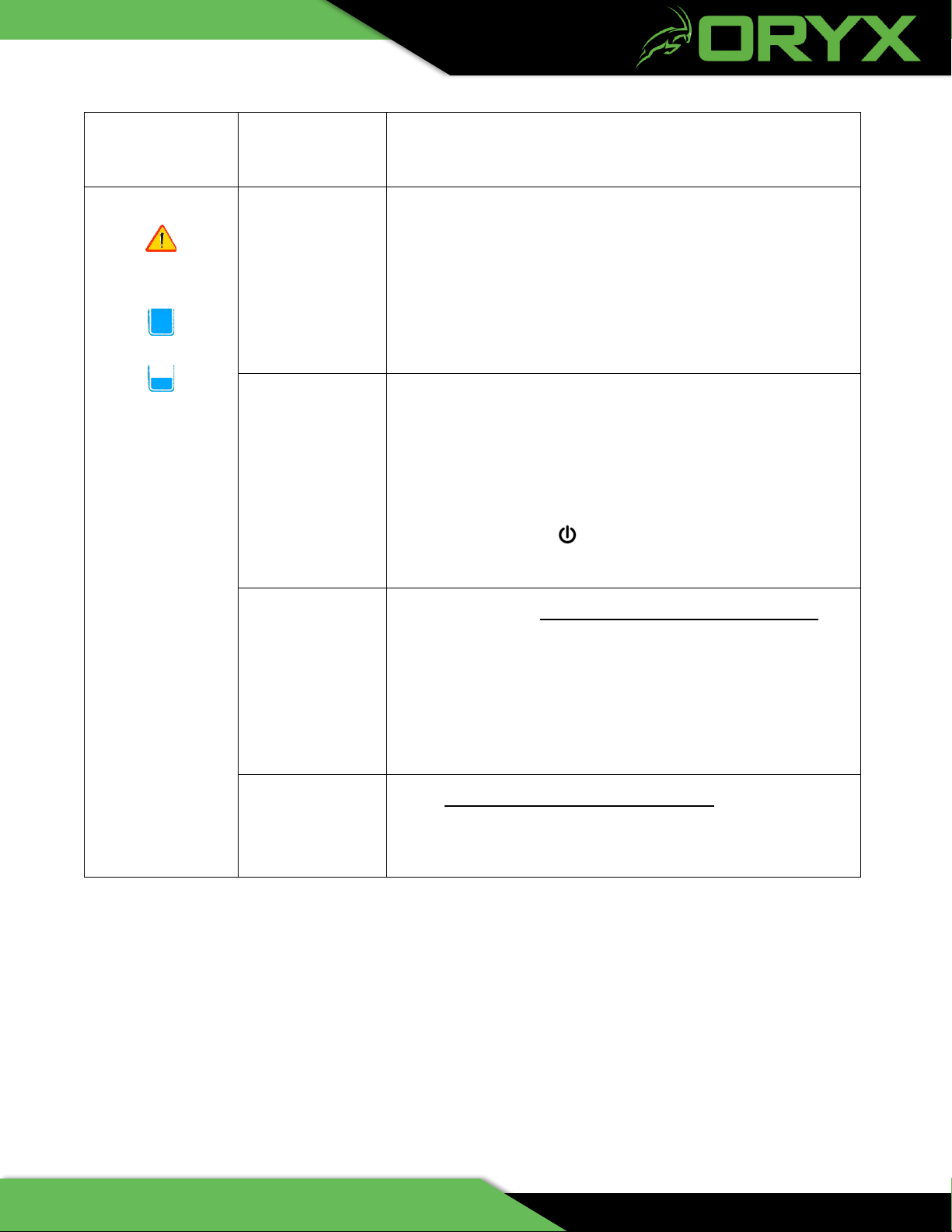
High Risk of Electrical Shock
Always disconnect the unit from power
before removing any cover!
Problem
Probable
Causes
What to Do
No Power to SCA
Power switch is
not “On”
Press rocker switch on the back of the unit to the “On” position.
Power cord is
not connected to
unit or wall
If the power switch LED is not lit when the power rocker switch
is turned on, check the power cord, and make sure it is pushed
all the way into the receptacle on the system and is securely
connected to a grounded wall socket. Check your building circuit
breakers, and any power circuit that the unit is plugged into for a
tripped circuit breaker or blown fuse. Reset or replace the
breaker or fuse as required.
Fuse is blown
With the power disconnected, check the continuity of F1, F2
(both mounted to the chassis) and FB1 and FB2 (both on the
PCB).
Thermal Cutoff
Switch (TCO) is
tripped or
defective
A resettable Thermal Switch located on the back wall of the tank
removes power from the SCA if the temperature of the bath
exceeds 90⁰C. Wait for the bath temperature to cool to < 80⁰ C.
Reset TCO, or ohm out TCO (See Check the Continuity of the
Thermal Cutoff Switch Section XII E).
PEM Defective
(See Check the Continuity of the PEM Section XII E)

AZ 85284
6
Problem
Probable
Causes
What to Do
Pump will not
start, SCA is
powered up,
display panel is
lit.
Timer has not
been set and
started
The system will only run when the timer is counting down. Check
the timer display on the control panel.
If it is not counting down, press the button. If the time being
displayed is 00:00, then add time and start the system as
described in the User Manual.
Pump is
defective
(See Pump Troubleshooting Section XII A).
Start Cap is
defective
(See Pump Troubleshooting Section XII A).
PCB is defective
(See Pump Troubleshooting Section XII A).
Start / Pause
switch is
defective
(See Pump Troubleshooting Section XII A).
AZ 85284
7
Problem
Probable
Causes
What to Do
Warning Indicator
Flashing
High Water
or Low Water
Indicator flashing
Liquid level is
too high or too
low
Check the indicator lights on the right side of the display control
panel. If either level indicator is on, add or remove water from the
tank until the indicator turns off.
ALWAYS WEAR PROTECTIVE GLOVES AND EYEWEAR
WHEN ADDING OR REMOVING LIQUID FROM THE TANK.
Basket is raised
or lowered too
quickly
If the basket is lowered into or raised out of the cleaning solution
too quickly, the solution does not fill or empty out fast enough to
maintain even water level throughout the tank. This causes a
temporary high or low water level condition. The alarm will silence
once the water level reaches acceptable limits, but the unit will not
operate again until the button is pushed.
Float movement
is impeded by
buildup on shaft
Remove float (See How to Remove the Sensor Assembly
Section V) and inspect. If there is a buildup on the shaft that
inhibits the free up and down motion of the float, clean off the
shaft. A scrub pad can be used to remove any buildup on the
shaft. Ensure the float moves freely from the bottom to the top of
the shaft.
Water level
sensor is
defective
(See Water Level Sensor Troubleshooting Section XII D).

AZ 85284
8
Problem
Probable
Causes
What to Do
Warning Indicator
Flashing
Error Code
Displayed
Internal Error
Sensor failure, power supply failure, or pump failure.
(See Error Codes Section XIII A).
Error Codes:
*EP = Pump motor current fault
*EH = Heater current fault
ES = 12VDC out of range, power supply error
EO = Over temperature
r1 = Temperature sensor failure
r2 = High level sensor failure
r3 = Low level sensor failure
*Only displayed on the original controllers without the “No Heat”
option
Not Heating, no
errors, pump is
circulating
Heater elements
have failed
(See Heating Element Troubleshooting Section XII B).
Temperature
sensor is
defective
(See Temperature Sensor Troubleshooting Section XII C).
Flow in tank
appears less than
normal
Flow from nozzle is
not uniform
White deposits
noticeable on
dark-colored
parts
The cleaning
solution is likely
saturated with
support material.
Drain the tank and add fresh water and cleaning solution as
described in the User Manual. Generally, when the PH balance
of the bath reaches 11.5, the effectiveness of the dissolution
drops dramatically.
Type of cleaning
agent.
If using Eco Works, try switching to Waterworks. Both are sold
by Stratasys resellers. Waterworks is a more efficient cleaning
concentrate.

AZ 85284
9
III. Removing Top Cover and Back Panel
A. How to Remove the Back Panel
1. Remove the Back Panel
a. With the SCA unplugged from power, remove the two screws on the top, center,
and bottom of the panel.
b. Loosen the remaining six M4 screws holding the back panel.
c. Push up on the back panel and remove.
Figure 1 - Removing the Back Panel
AZ 85284
10
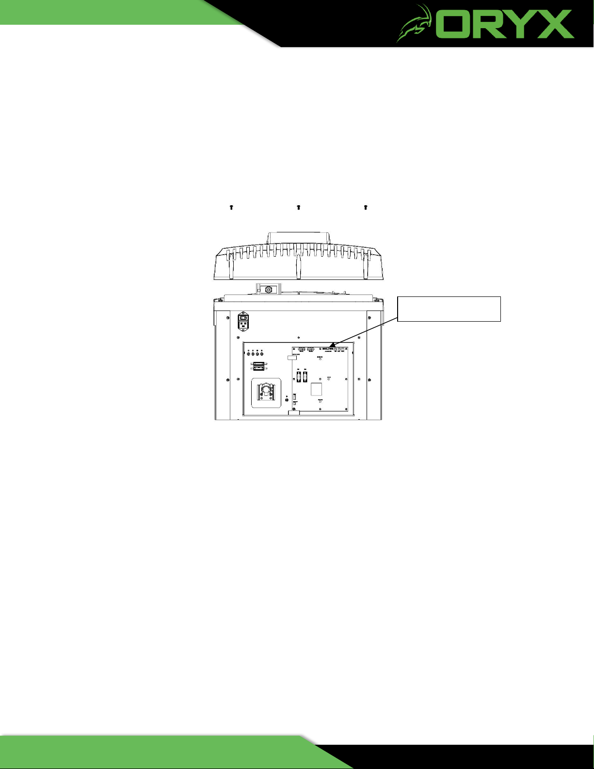
B. How to Remove the Top Cover
1. Remove the Top Cover
a. With the SCA unplugged from power, remove the J6 display ribbon cable from the
PCB.
b. Remove the three M5 screws.
c. Remove the cover by pushing lightly on the back of the cover.
Figure 2 – Removing the Top Cover
J6 Connector PCB

AZ 85284
11
IV. Pump Assembly Replacement
A. How to remove the Pump Assembly
1. Remove the Pump Assembly
a) Unplug the SCA from power and remove the back panel (See How to Remove the Back Panel
Section III A).
b) Remove the top cover (See How to Remove the Top Cover Section III B).
c) Disconnect the pump motor connector from the PCB Assembly.
Figure 3 - PCB Assembly
d) Remove the screw holding the motor ground wire.
e) Gently pull the motor wires through the bridge.
f) Unplug the three connectors from the sensors from the PCB.
g) Gently pull the sensor wires through the bridge
h) Remove the four M5 screws holding the pump assembly and ground wire.
i) Grip the motor and carefully remove the pump assembly.
Motor
Connector
Motor
Ground

AZ 85284
12
Figure 4 - Remove the Screws and Remove the Pump Assembly
j) Grip the pump assembly by the motor and carefully guide the pump assembly through the hole in
the bridge until the tray is seated on the gasket on top of the bridge.
B. How to install the Pump Assembly
1. Install the Pump Assembly
a) Grip the pump assembly by the motor and carefully guide the pump through the bridge until the
tray is seated on the gasket on top of the bridge
b) Mount the pump assembly to the bridge using the four M5 mounting screws and washers and
attach the wires to the tray.
c) Thread the motor wires through the bridge.
d) Attach the ground wire from the motor.
e) Plug in the connector from the motor to the PCB.
f) Thread the 3 sensor connectors through the bridge.
g) Plug in the 3 sensor connectors to the appropriate slots on the PCB.
h) Slide the back panel on and secure (See How to Remove the Back Panel Section III A).
i) Plug ribbon cable from the display back into the PCB.
j) Place cover ack on the SCA and secure (See How to Remove the Top Cover Section III B).
NOTE:
The tray gasket may cause the
pump assembly to stick to the
bridge. If this happens, loosen the
gasket by gently rocking the
assembly back and forth.
M5 Screws
(4 places)
AZ 85284
13
V. Sensor Assembly Replacement
A. How to Remove the Sensor Assembly
1. Remove the Sensor Assembly
a) Remove the back panel (See How to Remove the Back Panel Section III A).
b) Remove the top cover (See How to Remove the Top Cover Section III B).
c) Unplug the three sensor connectors from the PCB.
d) Remove the four M5 screws holding the sensor assembly.
e) Carefully pull the sensor wires through the bridge.
Figure 5 - Top View of SCA with Top Cover Removed
f) Carefully remove the Sensor Assembly from SCA.
M5 Screws
(4 places)
Sensor
Connectors

AZ 85284
14
Figure 6 - Remove Sensor Assembly
B. How to install the Sensor Assembly
1. Install the Sensor Assembly
a. Insert the Sensor Assembly into the motor tray.
b. Mount the Sensor Assembly using the four M5 screws.
c. Carefully thread sensor wires through the bridge.
d. Plug in the 3 sensor connectors into the appropriate slots on the PCB.
e. Plug in the display ribbon cable back into the PCB.
f. Slide the top cover panel and secure (See How to Remove the Top Cover Section III B).
g. Slide the back panel on and secure (See How to Remove the Back Panel Section III A).
NOTE: The gasket is
attached to the Sensor
Assembly.

AZ 85284
15
VI. Spray Nozzle Replacement
A. How to Replace the Nozzle
1. Replace the Nozzle
a) The 3600 has a Bayonet style nozzle that latches on to the pump output opening. Twist the
nozzle counter-clockwise to unlatch and clockwise to latch. Ensure the nozzle is tightly sealed on
the gasket and that it is correctly orientated (See Figure 8).
Figure 7 - Replacing the Spray Nozzle
Figure 8 - Correct Rotation of Spray Nozzle

AZ 85284
16
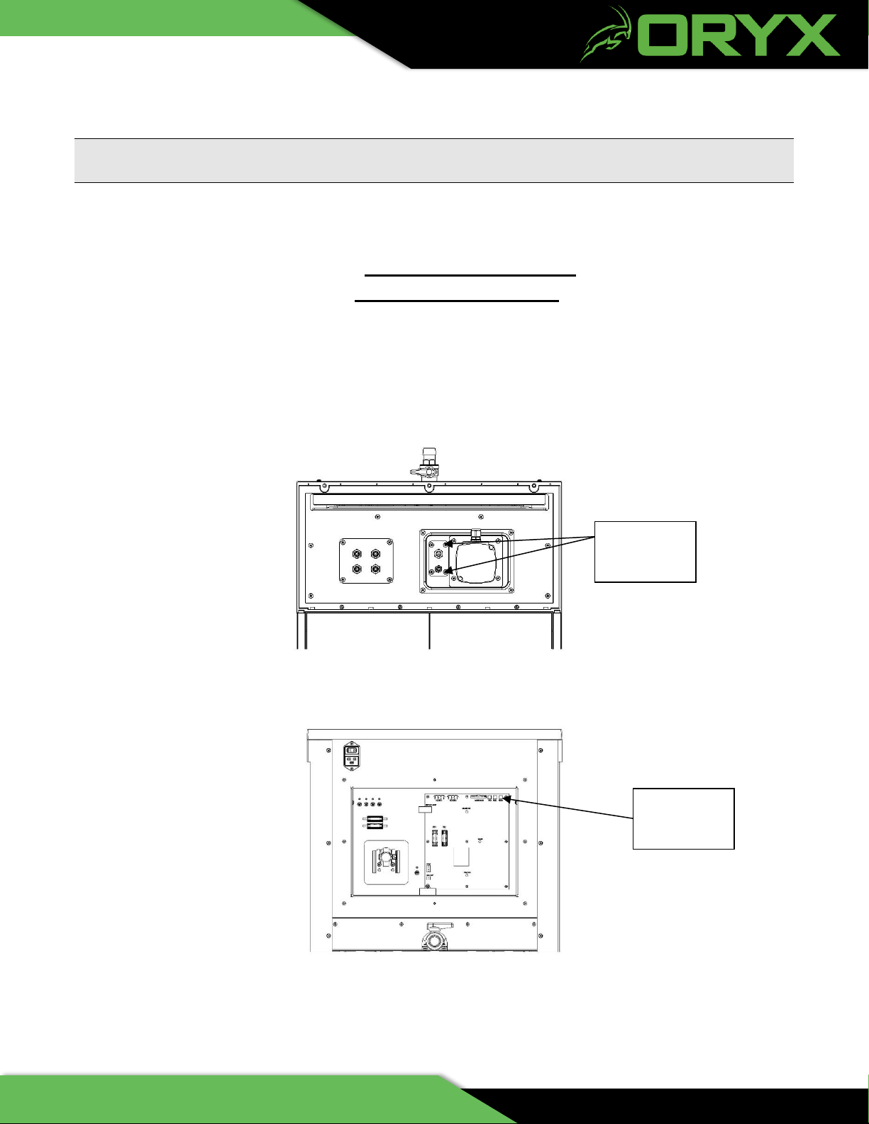
VII. Heater Assembly Replacement
A. How to Remove the Heater Assembly
1. Remove the Heater Assembly
a) Unplug the SCA from power and remove the back panel (See How to Remove the Back Panel
Section III A).
g) Remove the top cover (See How to Remove the Top Cover Section III B).
SHOCK HAZARD! PLEASE ENSURE POWER PLUG IS REMOVED FROM THE SCA.
b) Unplug the heater’s two connectors from the PCB Assembly.
Figure 9 – Heater Connectors
c) Gently pull the heater wires through the bridge.
d) Remove the four M5 screws holding the Heater Assembly and ground wire (See Figure 10).
Heater
Connectors

AZ 85284
17
ALLOW THE HEATING ELEMENT FOR COMPLETELY COOL BEFORE REMOVING.
e) Carefully remove the Heater Assembly from SCA
Figure 10 - Top View of the SCA with the Top Cover Removed
Figure 11 - Remove the Heater Assembly
M5 Screws
(4 places)

AZ 85284
18
B. How to Install the Heater Assembly
1. Install the Heater Assembly
a) Carefully guide the Heater Assembly through the hole in the Bridge until the plate is seated on the
gasket on top of the bridge.
b) Mount the Heater Assembly to the Bridge using the four M5 mounting screws and attach the
ground wire to the tray.
c) Carefully pull the heater wires through the Bridge.
d) Plug the three heater wire connectors back into the PCB.
e) Plug the ribbon cable from the display back into the PCB.
h) Place the top cover back on and secure with the six screws (See How to Remove the Top Cover
Section III B).
f) Place the back panel on to the SCA (See How to Remove the Back Panel Section III A).

AZ 85284
19
VIII. Display Control Panel Replacement
A. How to Remove the Display Control Panel
1. Remove the Display Control Panel
a) Unplug the SCA from power and remove the back panel (See How to Remove the Back Panel
Section III A).
b) Remove the top cover (See How to Remove the Top Cover Section III B).
c) Disconnect the display ribbon cable from the PCB.
d) Turn cover over and remove the six M4 screws inside over holding display.
Figure 12 - Remove Screws
e) Slide the display out of the cover.
Screws

AZ 85284
20
B. How to Install the Display Control Panel
1. Install the Display Control Panel
a) Thread the ribbon cable through the hole on the front of the top cover where the display will be
mounted.
b) Check the orientation of the display and proceed to press the display into the top cover.
c) Turn cover over and secure the display with the six M4 screws
d) Place the two supports over the posts and mount the supports to the post using the four M5
screws.
e) Plug the ribbon cable from display back into the PCB
i) Place the top cover back on and secure (See How to Remove the Top Cover Section III B).
f) Place the back panel on SCA and secure (See How to Remove the Back Panel Section III A).
Other manuals for sca3600
2
Table of contents
Other Oryx Ultrasonic Jewelry Cleaner manuals


