Osaka DG–CO2–3R–IP54 User manual

DG
DG–CO2–3R–IP54
DG–CO2–3R–IP54 (24)
DG–CO2–3R–IP67 (24)
OSAKA SOLUTIONS –www.osakasolutions.com –DG-CO2-3R –Instrucciones de Uso_V1 1
ESInstrucciones GBInstructions FRInstructions

DG
DG–CO2–3R–IP54
DG–CO2–3R–IP54 (24)
DG–CO2–3R–IP67 (24)
OSAKA SOLUTIONS –www.osakasolutions.com –DG-CO2-3R –Instrucciones de Uso_V1 2
Localización / Location / Emplacement
ES / GB / FR
(4)
- Niveles de alarma, configuración de fábrica
- Alarm levels, factory settings
- Niveaux d'alarme, réglages d'usine
Carbon Dioxid (CO2) (0-10000ppm)
Dioxyde de carbone (CO2)
Dióxido de carbono (CO2)
C=2000
B=2000
A=5000
X > 50 cm Y > 20 cm
H1 = 20 cm
H2 =150 cm
(CO2)H3 = 20 cm
DG
DG–CO2–3R–IP54
DG–CO2–3R–IP54 (24)
DG–CO2–3R–IP67 (24)
OSAKA SOLUTIONS –www.osakasolutions.com –DG-CO2-3R –Instrucciones de Uso_V1 3
ES
Este producto cumple con la directiva (LVD) 2006/95/EC y
(EMC) 2004/95/EC
Cumple con los requisitos de:
EN 61 000-6-2:2001
EN 61 000-6-3:2001
EN 61 000-3-2:2001
EN 61 000-3-3:1995
EN 61 010-1:2001
GB
This product is in conformity with
the directive (LVD) 2006/95/EC & (EMC) 2004/95/EC
It fulfils the requirements of:
EN 61 000-6-2:2001
EN 61 000-6-3:2001
EN 61 000-3-2:2001
EN 61 000-3-3:1995
EN 61 010-1:2001
FR
Le présent produit est conforme aux directives (DBT)
2006/95/CE et (CEM) 2004/95/CE.
Il répond aux exigences des normes suivantes :
EN 61 000-6-2:2001
EN 61 000-6-3:2001
EN 61 000-3-2:2001
EN 61 000-3-2:1995
EN 61 010-1:2001

DG
DG–CO2–3R–IP54
DG–CO2–3R–IP54 (24)
DG–CO2–3R–IP67 (24)
OSAKA SOLUTIONS –www.osakasolutions.com –DG-CO2-3R –Instrucciones de Uso_V1 4
ES
FUNCIONAMIENTO
Cuando se conecta la alimentación, parpadea un LED verde
para indicar que está encendido ”ON”. Esto también iniciará el
proceso de calentamiento del sensor. Después de
aproximadamente 4 minutos el LED verde se encenderá para
indicar ”Sensor activo”.
El detector cuenta con un LED amarillo y dos rojos. El LED
amarillo indica baja concentración de gas (Alarma C) y los LED
rojos indican concentración media de gas (Alarma B) y alta
concentración de gas (Alarma A).
Cuando se detecta gas los LED (2) se encenderán y el relé
cambiará de estado según el nivel de alarma que corresponda.
Si se opta por una alarma con retardo (ver a continuación) el
LED correspondiente parpadeará y se encenderá (cambiando
el retardo de estado) cuando exceda el tiempo del retardo.
REINICIO AUTOMÁTICO/MANUAL
El interruptor DIP (1) no3 en el que “on” (conectado) significa
reinicio automático y “off” (desconectado) significa reinicio
manual pulsando el botón de “Reinicio/Prueba/ Servicio”
(situado bajo la cubierta).
RETARDO DE LA ALARMA (T1)
Lo controlan los interruptores DIP (1) no1 y no2:
no1 no2
on on Sin retardo en la alarma
off on (1) minuto de retardo en la alarma
on off (10) minutos de retardo en la alarma
off off (30) minutos de retardo en la alarma
SEGURO CONTRA FALLOS
Los relés en modo normal tienen energía y cambiarán de
estado en caso de fallo de alimentación o si sucede una
situación de error.
FUNCIÓN DE AUTOCOMPROBACIÓN
Pulse el botón “Reinicio/Prueba/ Servicio” (5) durante 5
segundos y el programa de prueba se iniciará y revisará todas
las funciones LED y de relés en cinco intervalos.
FUNCIÓN DE FALLO
Si hubiera una caída de tensión (valor de GV inferior a 0,1V) en
el sensor se produce una situación de fallo. Durante las cuatro
primeras horas el LED verde se apagará y el resto de
LED parpadearán. El relé de alarma C cambiará de estado.
Después de cuatro horas, el LED “Alarma B” se encenderá (el
resto de LED se apagarán) y el relé “Alarma B” también
cambiará de estado.
INSTALACIÓN
Conectar el detector según el diagrama de cableado.
Las especificaciones están sujetas a cambios.
FUNCIÓN DE SERVICIO
Al pulsar el botón ”Reinicio/Prueba/ Servicio” (5) durante 10 se
bloquearán todas las funciones de alarma durante 60 minutos.
Durante este periodo siempre será posible iniciar un nuevo
periodo de 60 segundos pulsando de nuevo el botón durante 10
segundos. Al final del periodo de 60 minutos, se regresa al
estado activo de forma automática o de forma manual pulsando
el botón “Reinicio/Prueba/ Servicio”. Cuando la función de
servicio se encuentra activada todos los LED parpadearán y los
relés estarán en posición de modo normal.
CALIBRACIÓN
Los detectores se entregan para un tipo de gas específico por lo
que normalmente no son necesarias otras calibraciones. La
denominación del detector se realiza según el tipo de gas que
detecta. Sin embargo, es muy sencillo cambiar los umbrales
utilizando un adaptador de servicio.
CONTROL DE FUNCIONAMIENTO ANUAL
Se recomienda probar el equipo al menos dos veces al año.
Un control y calibración mayor requerirá el uso de un gas de
prueba con una concentración determinada.
Para más información, contacte con nosotros.
TENGA EN CUENTA
El DG-CO2-3R-IP67 (24) tiene un elemento de calentamiento
interno para mantener la óptica libre de niebla. Asegúrese de que
los cables y fuente de alimentación con capacidad suficiente!
INFORMACIÓN TÉCNICA
Caja: Policarbonato, PC, IP67
Alimentación: 230V CA, 50/60Hz
12..24V CA/CC (modelo DG…(24))
Consumo de energía: DG-CO2-3R-IP54 máx 2VA
DG-CO2-3R-IP67 (incl. calentadores);
max 14VA
Indicaciones: Conexión/Activo y tres niveles de
indicación de alarma.
Relés de salida: Contactos sin potencial (230V, máx 5A) .
Temp. ambiente: DG-CO2-3R-IP54; 00C..+500C
DG-CO2-3R-IP67; -400C..+ 500C
Humedad: 0-95% Hr (sin condensación)
Juntas: 4 juntas de membrana M16
Terminales de tornillo: < 1,5 mm2, fusible < 10A
ATENCIÓN!
Riesgo de alta tensión bajo la tapa!
El aparato sólo puede ser abierto por personal
autorizado!
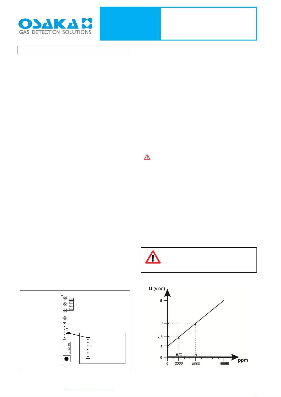
Sensor de señal para el módulo de CO2
con un rango de 0-10000 ppm:
n 4 no utilizado
n 1
n 2
n 3 REESTABLECER ALARMA: ON=AUTO, OFF=MANUAL
ON
A
REINICIAR/PRUEBA
PROBAR TERMINAL
C
B
LED A
LED B
LED C
ENERGÍA
ALARMA A
ALARMA B
ALARMA C
(-)
+ 5VDC
ESTABLECER
GV OFF

DG
DG–CO2–3R–IP54
DG–CO2–3R–IP54 (24)
DG–CO2–3R–IP67 (24)
OSAKA SOLUTIONS –www.osakasolutions.com –DG-CO2-3R –Instrucciones de Uso_V1 5
GB
FUNCTION
When power supply is switched on, a green LED will flash to
indicate power ”ON”. This will also start the heating process of
the sensor. After approximately 4 minutes the green LED will
light and indicate ”Sensor Active”.
The detector has one yellow and two red LEDs. The yellow LED
indicates low gas concentration (Alarm C) and the red LEDs
indicate medium gas concentration (Alarm B) and high gas
concentration (Alarm A).
When gas is detected the LEDs (2) will light and the relay
corresponding to the alarm level will change state. If alarm
delay is chosen (see below) the respective LED will flash and it
will light (and the relay will change state) when the chosen
delay time is exceeded.
AUTOMATIC/MANUAL RESET
Is managed by DIP switch (1) no3 where “on” means automatic
reset and “off” means manual reset by pressing the “Reset/Test/
Service”-button (located under the cover).
ALARM TIME DELAY (T1)
Is managed by DIP-switches (1) no1 and no2:
no1 no2
on on No alarm delay
off on (1) minutes alarm delay
on off (10) minutes alarm delay
off off (30) minutes alarm delay
FAIL SAFE
Relays are in normal mode energized and will change state if
power failure or if a fault situation occurs.
SELF TEST FUNCTION
Press the “Reset/Test/Service”-button (5) for 5 seconds and the
test program will start and go through all LED functions and all
relay functions in five seconds intervals.
FAULT FUNCTION
If there is a voltage drop (GV-value below 0,1V) from the sensor
there is a fault situation. During the first four hours the green
LED will go out and the other LED’s will flash. Alarm relay C will
change state.
After four hours the LED “Alarm B” will light (other LED’s will go
off) and relay “Alarm B” will also change state.
INSTALLATION
Connect the detector according to the wiring diagram.
Specifications subject to change.
SERVICE FUNCTION
Pressing the ”Reset/Test/Service” button (5) for 10 seconds will
lock all alarm functions for 60 minutes. During this period it is
always possible to start a new 60-minutes period by pressing the
button for 10 seconds again. Return to active status is automatic
at the end of the 60-minutes period or may be done manually by a
single press on the “Reset/Test/Service”-button. When the service
function is activated all LED’s will flash and all relays will be in
normal mode position.
CALIBRATION
The detectors are delivered for a specific gas type and other
calibrations are normally not necessary. The detector is named
with the required gas type being detected. It is, however, very
easy to change the thresholds by using a service adapter.
ANNUAL FUNCTION CONTROL
Testing the system is recommended to be done at least twice a
year.
Extended control and calibration requires also test gas with a
specific concentration.
Contact us for more information.
PLEASE NOTE
The DG-CO2-3R-IP67 (24) has an internal heating element to
keep the optics free of fog. Make sure cables and power supply
have sufficient capacity!
TECHNICAL DATA
Housing: Polycarbonate, PC, IP67
Power supply: 230V AC, 50/60Hz
12..24V AC/DC (modelo DG…(24))
Power consumption: DG-CO2-3R-IP54 max 2VA
DG-CO2-3R-IP67 (incl. heater); max
14VA
Indications: Power/Active and alarm indication on
three levels.
Outputs relay: Potential free contacts (230V, max 5A)
Ambient temp: DG-CO2-3R-IP54; 00C..+500C
DG-CO2-3R-IP67; -400C..+ 500C
Humidity: 0-95% Rh (non condensing)
Glands: 4 of M16 membrane glands
Screw terminals: < 1,5 mm2, fuse < 10A
ATTENTION!
Risk of high voltage under the lid!
The device may only be opened by authorized
personnel!
Sensor signal for CO2module with range 0-10000ppm:
n 4 not used
n 1
n 2
n 3 ALARM RESET: ON=AUTO, OFF=MANUELL
ON
A
RESET/TEST
TEST TERMINAL
C
B
LED A
LED B
LED C
POWER
ALARM A
ALARM B
ALARM C
(-)
+ 5VDC
GV OFFSET
DG
DG–CO2–3R–IP54
DG–CO2–3R–IP54 (24)
DG–CO2–3R–IP67 (24)
OSAKA SOLUTIONS –www.osakasolutions.com –DG-CO2-3R –Instrucciones de Uso_V1 6
FR
FONCTIONNEMENT
Lorsque l'alimentation électrique est enclenchée, un voyant
DEL vert clignote pour indiquer que le détecteur est sous
tension (”ON”). De plus, le processus de chauffe de la sonde
est enclenché. Après environ 4 minutes, le voyant DEL vert est
allumé et indique ”Sensor Active” (Sonde active).
Le détecteur comporte un voyant DEL jaune et deux voyants
DEL rouges. Le voyant DEL jaune indique une faible
concentration de gaz (alarme C). Les voyants DEL rouges
indiquent une concentration de gaz moyenne (alarme B) et une
concentration de gaz élevée (alarme A).
Lorsque du gaz est détecté, les voyants DEL (2) s'allument et
le relais correspondant au niveau de l'alarme change d'état. En
cas de sélection d'une temporisation d'alarme (voir ci-dessous),
le voyant DEL correspondant clignote. Il reste allumé en
permanence (et le relais change d'état) lorsque la durée de
temporisation sélectionnée est dépassée.
RÉINITIALISATION AUTOMATIQUE/MANUELLE
Contrôlée par le commutateur DIP (1) no3 ; "ON" indique la
réinitialisation automatique et "OFF" la réinitialisation manuelle
(en appuyant sur le bouton "Reset/Test/Service", situé sous le
couvercle).
TEMPORISATION DES ALARMES (T1)
Contrôlée par les commutateurs DIP (1) no 1 et no 2 :
No 1 No 2
ON ON Aucune temporisation d’alarme
OFF ON Temporisation de (1) minute
ON OFF Temporisation de (10) minutes
OFF OFF Temporisation de (30) minutes
SÉCURITÉ INTÉGRÉE
En mode de marche normal, les relais sont sous tension et
change d'état en cas de panne de courant ou défaillance.
FONCTION D'AUTO-VÉRIFICATION
Appuyer sur le bouton "Reset/Test/Service" (5) pendant 5
secondes et le programme d'essai s'enclenche et contrôle
toutes les fonctions DEL et toutes les fonctions de relais par
intervalles de cinq secondes.
DÉFAILLANCE
Par "défaillance", il est entendu les cas où l'alimentation
électrique de la sonde chute (valeur GV inférieure à 0,1 V).
Pendant les quatre premières heures, le voyant DEL vert est
éteint et les autres voyants DEL clignotent. Le relais d'alarme C
change d'état. Après quatre heures, le voyant DEL "Alarm B"
s'allume (les autres voyants DEL s'éteignent) et le relais “Alarm
B” change d'état.
INSTALLATION
Raccorder le détecteur conformément au schéma de câblage.
Sous réserve de modifications
FONCTION DÉPANNAGE/ENTRETIEN
Appuyer sur le bouton "Reset/Test/Service" (5) pendant 10
secondes pour verrouiller toutes les fonctions d'alarme pendant
60 minutes. Durant cette période, il est toujours possible de
lancer une nouvelle période de 60 minutes en appuyant une
nouvelle fois sur le bouton pendant 10 secondes.. Le retour à
l'état actif se fait automatiquement à l'issue des 60 minutes ou
peut être opéré manuellement en appuyant une seule fois sur le
bouton "Reset/Test/Service". Lorsque la fonction de
dépannage/entretien est activée, tous les voyants DEL clignotent
et tous les relais sont en position de marche normale.
ÉTALONNAGE
Chaque détecteur est conçu pour un type de gaz spécifique.
Aucun étalonnage ultérieur n'est donc généralement requis. Le
nom du détecteur indique le type de gaz à détecter. Néanmoins, il
est très facile de modifier les seuils d'étalonnage à l'aide d'un
adaptateur.
CONTRÔLE DE FONCTIONNEMENT ANNUEL
Il est recommandé de tester le système deux fois par an.
Un contrôle et un étalonnage plus vastes requièrent également
un gaz d'essai à concentration spécifique.
N'hésitez pas à nous contacter pour de plus amples informations.
S'IL VOUS PLAÎT NOTE
Le DG-CO2-3R-IP67 (24) a un élément chauffant interne pour
préserver les optiques sans brouillard. Assurez-vous que les
câbles et l'alimentation d'une capacité suffisante!
SPÉCIFICATIONS TECHNIQUES
Boîtier : Polycarbonate, PC, IP67
Alimentation électrique : 230V c.a., 50/60Hz
12..24V c.a./c.c. (modelo GD… (24))
Consommation électrique: DG-CO2-3R-IP54 max. 2VA
DG-CO2-3R-IP67 (y compris
chauffe); max 14VA
Indications : Indication de mise sous tension/actif
et d'alarme sur trois niveaux.
Relais de sortie : Interrupteurs neutres (230 V, max.5A
Temp. ambiante : DG-CO2-3R-IP54; 00C..+500C
DG-CO2-3R-IP67; -400C..+ 500C
Humidité : 0-95 % HR (sans condensation)
Presse-étoupes : 4 presse-étoupes à membrane M16
Bornes à vis : < 1,5 mm2, fusible < 10 A
ATTENTION!
Risque de haute tension sous le couvercle!
L'appareil ne doit être ouvert que par du
personnel autorisé!
Signal du capteur pour le module CO2
avec la gamme 0-10000ppm:
n 4 non utilisé
n 1
n 2
n 3 RÉINITIALISATION DE L’ALARME : ON=AUTO,
OFF=MANUEL
ON
A
RESET/TEST
BORNE D'ESSAI
C
B
DEL A
DEL B
DEL C
ALIMENTATION
ALARME A
ALARME B
ALARME C
(-)
+ 5 V c.c
GV OFFSET
This manual suits for next models
1
Table of contents
Languages:
Other Osaka Gas Detector manuals


Popular Gas Detector manuals by other brands

Vighnaharta
Vighnaharta TS21 I IR CO2 user manual

ESP Safety
ESP Safety TGAES 100-0023-02 Quick installation guide

De Nora
De Nora Capital Controls CHLORALERT 17CA3000 Series instruction manual

BEINAT
BEINAT GS913- V.6 manual

General Monitors
General Monitors TS4000H Communications manual

RKI Instruments
RKI Instruments 65-2428 Operator's manual


