Vighnaharta TS21 I IR CO2 User manual

Vighnaharta Technologies Pvt. Ltd.
2nd Floor,Karanjkar Estate,
S.N.11/11,Nanded Gaon,
Pune-411041
Tel no.: + 1 01103325 , Sales: + 1 011033260
Email: sales@vighnaharta.in | Website: http://www.vighnaharta.in
Prepared By:
MDC
Approved By: JG
Doc No
.:
TS21I_IR
_CO2
_UM_
2
_
0
Rev.No.: 2_0
Eff.Date.: 23-05-2020
TS21I _IR_ C O2
US E R MAN U AL
Mfg. By:
Vighnaharta Technologies Pvt. Ltd.
2nd Floor,Karanjkar Estate,S.N.11/11,Nanded Gaon,Pune-411041
Contact no.: + 1 01103325 (Landline) Sales: + 1 011033260
Email: sales@vighnaharta.in | Website: http://www.vighnaharta.in

TS21I_IR_CO2 User Manual
Vighnaharta Technologies Pvt Ltd Page 2 of 13
Table of Contents
Overview .................................................................................... III
Technical Specifications .............................................................. IV
Installation Procedure ................................................................. IV
Operation .................................................................................... VI
Menu etails ................................................................................. X
Calibration process ...................................................................... XI

TS21I_IR_CO2 User Manual
Vighnaharta Technologies Pvt Ltd Page 3 of 13
Overview
TS21I_IR_CO2is a Gas Detector to use CO2 (carban dioxide) gas leakage. The detector is designed
to detect gas leakage in theindustrial premises with the help of IR (Infrared) gassensor. The gas
detecting sensor is kept inside Central Mining Research Institute (CMRI) certified flameproof
enclosure. It is a Microcontroller based detector which reads sensor output and indicates the
concentration of actual gas present in atmosphere. It is measured in %v(volume). It is commonly
used in beverage industry, car parking area, etc. For HVAC applications, CO2 sensors can be used
to monitor the quality of air and the tailored need for fresh air, respectively. Measuring CO2 levels
indirectly determines how many people are in a room, and ventilation can be adjusted accordingly.
Salient Features
•Detection Gas:- CO2(carban dioxide)
•Gas Detection Range (%v/v):- 0 to 5%v/v with user defined high and low alarm level.
•Four digit seven segment LED display for%v/v level indication.
•3 potential free relay output with selectable NO / NC outputs.
•Digital input for gas valve status feedback only for Modbus monitoring. (NC)
•Four magnetic keys which can be operated using magnetic stylus.
•RS485 port for networking multiple gas detectors to building management system.
•Supports MODBUS RTU protocol.
•Supply Under voltage and over voltage indication.
•Sensor fault indication.
•Password protected menu

TS21I_IR_CO2 User Manual
Vighnaharta Technologies Pvt Ltd Page 4 of 13
Technical Specifications
Power Supply
Input- 24 VDC, 200mA
Input
4 Magnetic keys
, DI (Normally Closed)
Indication
LED indication for following status:
1. Power ON: green LED
2. Low Alarm: yellow LED
3. High Alarm: red LED
4. Fault condition : orange LED
Output 1.Three potential free relay output with NO / NC
Selectable
2. 0-5V OR 0-10V analog output
3. 4-20mA current output
Operating Temperature -10C°to 55C°
Humidity 0 to 5 % Rh.
RS485 Interface
Modbus RTU Protocol
Enclosure
Aluminium casting
Installation Procedure
Prerequisites:
The convenient location for mounting the system must be finalized.
•TS21I_IR_CO2 unit
•Power supply adapter ( Optional)
•mounting screws
•User manual
•Screw driver
•Allen Key set
To install the unit at the user premises
1. Run all desired power, siren and hardware contact wires to the panel location.
2. Level the cabinet on sturdy wall and mark the mounting holes with a pencil.
Installation precautions
•This detector head in the flame proof enclosure must be installed near the CO2 gas cylinders or
at the joints of gas carrying pipes.
•The detector must face down to cater for heavier than air gases.
•CO2 is heavier than air, it has tendency to settle down. Hence, if you are using CO2 cylinder,
install the unit up to 30cm above floor.
Don’ts
•Don’t use the unit in direct sunlight.
•Don’t expose the sensor to gas concentration higher than its prescribed range.
•Don’t immerse the unit in any liquid.
•Don’t attempt to clean the detector from inside.
•Don’t open the flameproof enclosure when gas is present.
•Don’t switch high voltage or power loads through the relay, use only as potential free contacts.

TS21I_IR_CO2 User Manual
Vighnaharta Technologies
Pvt Ltd
Page
5
of
13
Connector Details of the unit
Connector CON1:
Pin No. escription
10. R1COM (Relay 1 common)
11. R1NO (Relay 1 NO)
12. R2COM (Relay 2 common)
13. R2NO (Relay 2 NO)
14
.
R3COM (Relay 3
common)
15
.
R3
NO
(Relay 3
NO)
Connector CON2:
Pin No.
escription
1. D+ (RS 485 data +)
2. D- (RS485 data -)
3
.
C+ (+ve current Output)
4
.
C
-
(
-
ve c
urrent Output)
5
.
A
-
O/P+ (+ve analog output voltage)
6. A-O/P- (-ve analog output voltage)
7. DI (Digital Input)
8. VCC
. GROUND
Connecting wires
•Take out the wires from supply, relay output and RS 485 port.
•Make the connections for relay and RS 485 as mentioned in above table.
•Take out wires from output and connect it to desired instrument.
•Insert power adapter to the mains socket.

TS21I_IR_CO2 User Manual
Vighnaharta Technologies
Pvt Ltd
Page
6
of
13
Operation
When unit is power ON, it goes in to an initial warm up period of 0 seconds. After this period is
over, unit enters into scan mode when it continuously monitors gas concentration level in the
atmosphere. When gas concentration exceeds low or high alarm threshold levels, relay output
changes accordingly. It shows gas concentration level between 0 and 5%v/v with LED indication
on front panel. TS21I_IR_CO2 has two settable alarm levels. Low alarm level and High alarm level.
Fault Relay operate on supply voltage below 18V or more than 2 V and also according sensor open
or short with LED indication on front panel.
It uses four magnetic keys which operate using single magnetic stylus to do settings like low / high
alarm levels, relay output type and so on.
Front panel of typical TS21I_IR_CO2 is shown as below.
Relay Settings:
TS21I_IR_CO2 has threerelay outputs:-
Relay1 for low alarm condition,Relay2 for high alarm condition and Relay3 for Fault operation.
User can use it as a NO or NC type output using the respective jumper adjustments. User can set
relay output type for both relays as PULSE type or LATCH type.
Pulse type output: Relay trips for 5 sec and comes back to its previous state.
Latch type output: Relay remains latched till the unit is reset.
If unit is connected to a Gas Detection Panel,using MODBUS communication, the Gas Detection
Panel gives an alert depending on the status of TS21I_IR_CO2.
POWER ON
LED
4 Digit LED
Display
Low and High
Alarm LED
Fault LED
Press Key to
enter into Menu
Press Key
to Exit

TS21I_IR_CO2 User Manual
Vighnaharta Technologies
Pvt Ltd
Page
7
of
13
Jumpers to set NO/NC contacts for relays
In above picture, there are three jumpers shownJP1 used to set Relay1,JP2 used to set
Relay2and JP3 used to set Relay3. Using these jumpers, user can set NO type contact or NC
type of contact.
For Relay1JP1,
Jumper between pin 1 and 2, Relay1 will be NC type
Jumper between pin 2 and 3, Relay1 will be NO type
JP1
For Relay2JP2,
Jumper between pin 1 and 2, Relay2 output will be NC type
Jumper between pin 2 and 3, Relay2 output will be NO type
JP2
For Relay3JP3,
Jumper between pin 1 and 2, Relay3 will be NC type
Jumper between pin 2 and 3, Relay3 will be NO type
JP3
1
2
3
1
2
3
1
2
3
Jumper 2
Jumper 3
Jumper 1

TS21I_IR_CO2 User Manual
Vighnaharta Technologies
Pvt Ltd
Page
8
of
13
Modbus Settings:
The following connection diagram showsTS21I_IR_CO2 units connected with Gas Detection Panel.
Siren and power connector locations are shown as below.
Gas etection Panel (G P-32) Connection iagram with TS21I_IR_CO2 units
To communicate TS21I_IR_CO2 unit with gas detection panel, user must set proper slave address
using Interaction. Maximum of 254 slave IDs can be set using Interaction. Refer Interaction
details.
Note: If user set wrong slave address, then unit may not be able to communicate with gas
detection panel.
Modbus Communication:-
efault Settings for TS21I_IR_CO2
Baud Rate 600 bps
Parity Even
Relay 1 NO, O/P: PULSE type
Relay 2
NO, O/P: PULSE type
Relay 3 NO, O/P: PULSE type
Output Voltage
0
-
10Volts
S.NO
function
code address
function
1 1 101
Read DO2 status High
Alarm
1 102
Read DO1 status Low
Alarm
*2 2 1 Read DI
3 3 1001/1 Reserved
TS21I_IR_CO
2
evice 1
TS21I_IR_CO2
evice 2

TS21I_IR_CO2 User Manual
Vighnaharta Technologies Pvt Ltd Page 9 of 13
1008 %v/v Higher 16-bit
100 %v/v Lower 16-bit
4 3 1002/2 Read Threshold Low
3 1003/3 Read Threshold High
5 4 1002/2 Read Threshold Low
4 1003/3 Read Threshold High
6 5 101 Write D02 High Alarm
5 102 write D01 Low Alarm
7 6 1002 Write Threshold Low
6 1003 Write Threshold High
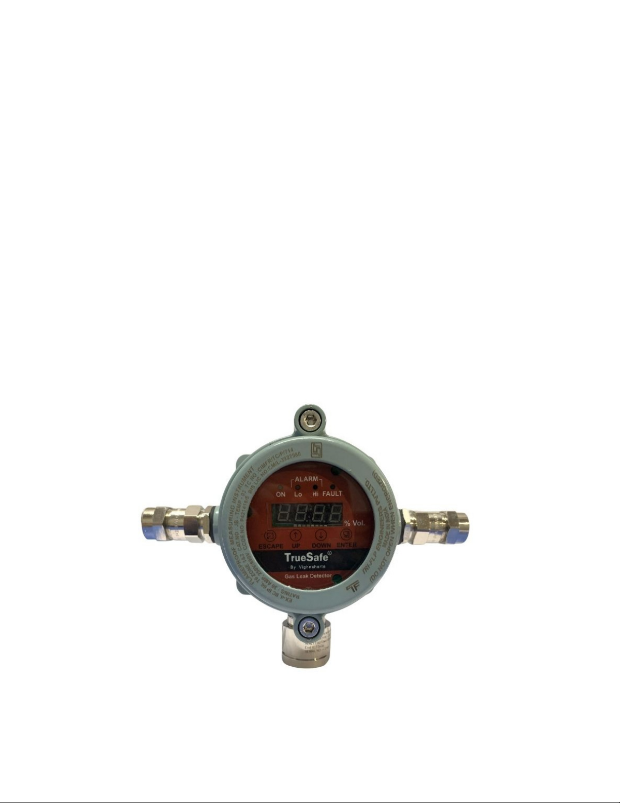
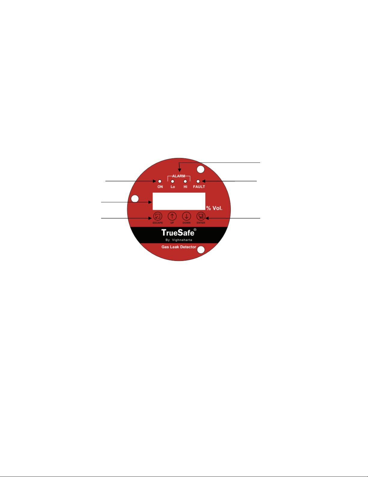
Understanding controls on front panel
LE Indicators
1. ON Power ON LED. Green LED turns on when power is ON. It
indicates Power On status of the unit.
2.
L
–
Alarm
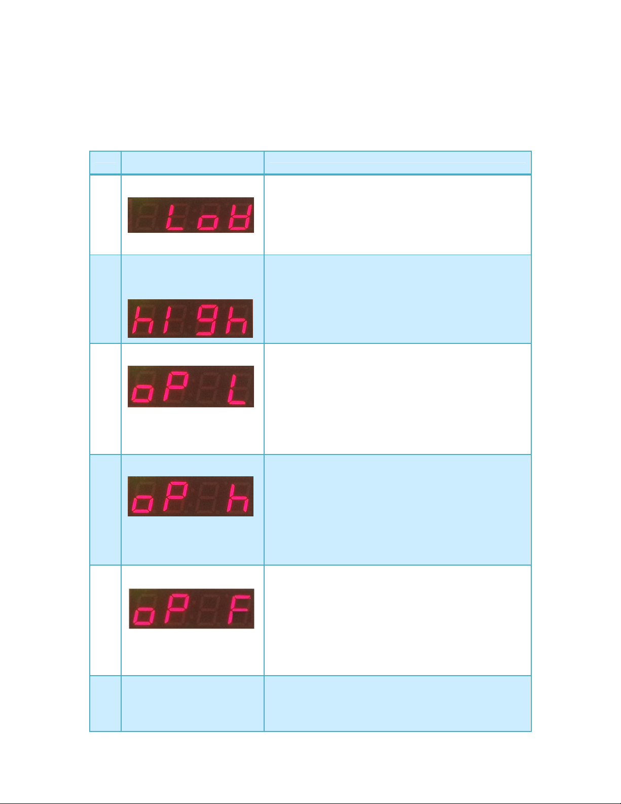
When gas concentration exceeds low threshold level,
TS21I_IR_CO2 generates low alarm condition. For low alarm
condition, yellow LED turns ON till unit is reset.If relay1 output
is pulse type, relay remains on for 5sec. If relay1 output is
latch type, relay remains on till the unit is reset.
3. H- Alarm When gas concentration exceeds high threshold level,
TS21I_IR_CO2 generates high alarm condition. For high alarm
condition, red LED turns ON till unit is reset. If relay2 output is
pulse type, relay remains on for 5sec. If relay2 output is latch
type, relay remains on till the unit is reset.
3. F- Alarm When supplay goes below 1 V or above 2 V and also sensor
status open or short. Orange LED turns ON till unit is reset. If
relay3 output is pulse type, relay remains on for 5sec. If
relay3 output is latch type, relay remains on till the unit is
reset.
4.
LE isplay
Four digits
-
Seven Segment LED displa
y shows the cu
rrent
gas concentration in %v/v. Also it shows configuration settings
like current / voltage range.
Example, the seven segments LED display shows the 0.046
%v/vof gas concentration.
Magnetic Keypad - Four magnetic keys operate using magnetic stylus.
1.
ENTER Move stylus to ENTER key to enter into system to access
menus. This key has dual function. It is used to Enter or Save
the data. User can select some menu or can save settings
made by the user. If user presses the key during Idle mode, it
displays the menu.
2. ESCAPE Move stylus to ESCAPE key to exit from the current menu. If
user exits without saving, current settings will not be saved.
3.
UP
Move stylus to
UP
key to move menu up side or increment the
menu.
4. OWN Move stylus to OWN key to move menu down side or
decrement the menu.
0 .0 4 6

TS21I_IR_CO2 User Manual
Vighnaharta Technologies Pvt Ltd Page 10 of 13
Menu Details
Menus available in TS21I_IR_CO2
To go to menu, press ENTER key. UseUp and own keys to select the desired function. To use
the functions, follow the steps given in the table.
Function names in the
menu
Process Steps
1.
Low
(Low Alarm Threshold
Level for gas detection)
1.
Press
Enter
key to go in main menu.
2. Press Enter key to select ‘Low’ function.
3. Use Up and own keys to increment and decrement
low alarm threshold level.
4. Press Enter key to save the settings or press Escape
to return to previous menu without saving the settings.
2. High (High Alarm
Threshold Level for gas
detection)
1. Press Enter key to go in main menu.
2. Press own key to scroll and select the function.
3. Press Enter key to select ‘High’ function.
4. Use Up and own keys to increment and decrement
high alarm threshold level.
5. Press Enter key to save the settings or press
Escapekey to return to previous menu without saving
the settings.
3. oP L (Output Low)
User can set Relay1 output as either PULSE or LATCH
type.
1. Press ENTER to go in main menu.
2. Use own Key to select ‘oP L’ function.
3. To go into ‘oP L’ function, again press ENTER key.
4. Use Up and own keys to select PULSE or LATCH type
for Relay1 output.
5. Press Enter key to save the settings or press
Escapekey to return to previous menu without saving
the settings.
4.
oP h (Output High)
User can set Relay2 output as either PULSE or LATCH
type.
1. Press ENTER to go in main menu.
2. Use own key to select ‘oP h’ function.
3. To go into ‘oP h’ function, again press ENTER key.
4. Use Up and own keys to select PULSE or LATCH type
for Relay2 output.
5. Press Enter key to save the settings or press
Escapekey to return to previous menu without saving
the settings.
5. oP F (Output Fault)
User can set Relay3 output as either PULSE or LATCH
type.
1. Press ENTER to go in main menu.
2. Use own key to select ‘oP F’ function.
3. To go into ‘oP F’ function, again press ENTER key.
4. Use Up and own keys to select PULSE or LATCH type
for Relay3 output.
5. Press Enter key to save the settings or press Escape
key to return to previous menu without saving the
settings.
6. rSt (Reset)
To reset TS21I_IR_CO2 unit, manual reset facility is
provided to user.
1. Press ENTER to go in main menu.
2. Use Up and own keys to move menu up and down
and select ‘rSt’.

TS21I_IR_CO2 User Manual
Vighnaharta Technologies Pvt Ltd Page 11 of 13
3. Press ENTER to select the ‘rSt’ function.
Unit gets reset and goes into warm-up period for 20
seconds.
Calibration process
TS21I_IR_CO2:-
TS21I_IR_CO2 needs to be calibrated once in year from factory. As year passes there is
some drift in sensor output that’s why this calibration requires.
Function names in the menu Process Steps
1
.
o1ZC
(Output 1 Zero calibration)
This is a calibration function used
to calibrate current output for
4mA.
o1SC
(Output 1 Span calibration) This
is a calibration function used to
calibrate current output for
20mA.
1.
Go to menu
o1ZC
.
2. Measure current between C+ and C- connections on
CON2.
3. Press Up or own key to increase or decrease the
count to get 4mA output across C+ and C-.
4. Press ENTER key to save the count.
5. Go to menu o1SC.
6. Measure current between C+ and C- connections on
CON2.
7. Press Up or own key to increase or decrease the
count to get 20mA output across C+ and C-.
8. Press ENTER key to save the count.
. Press ESCAPE key to exit from Configuration mode
and remain in Idle or Scan mode.
2. o2ZC
(Output 2 Zero calibration)
This is a calibration function used
to calibrate voltage output for
0V.
o2SC
(Output 2 Span calibration) This
is a calibration function used to
calibrate voltage output for 5 /
10V depending on voltage range
set in menu A oP.
1. Go to menu A oP.
2. Press Up or own key to select 0 – 5v or 0 -10v
range.
3. Go to menu o2ZC.
4. Measure voltage between A-O/P and GND
connections on CON2.
5. Press Up or own key to increase or decrease the
count to get 0V output across A-O/P and GND.
6. Press ENTER key to save the count.
7. Go to menu o2SC.
8. Measure voltage between A-O/P and GND
connections on CON2.
. Press Up or own key to increase or decrease the
count to get 5v or 10v output across A-O/P and
GND.
10. Press ENTER key to save the count.
11. Press ESCAPE key to exit from Configuration mode
and remain in Idle or Scan mode.
3
.
bAUd
User can set baud rate either 2400, 600,1 200.
1. Press ENTER to go in main menu.
2. Use own key to select ‘bAUd’ function.
3. To go into ‘bAUd’ function, again press ENTER key.
4. Use Up or own keys to select any one baud rate

TS21I_IR_CO2 User Manual
Vighnaharta Technologies Pvt Ltd Page 12 of 13
Function names in the menu Process Steps
from following option 2.4(2400), .6( 600),
1 .2(1 200).
5. Press Enter key to save the settings or press
Escape key to return to previous menu without
saving the settings.
4
.
P
A
rt
User can set Parity either None, Even, Odd.
1. Press ENTER to go in main menu.
2. Use own key to select ‘PArt’ function.
3. To go into ‘PArt’ function, again press ENTER key.
4. Use Up or own keys to select any parity from
following option ‘nonE’ (None), ‘EuEn
’ (Even),
‘_odd’ (Odd).
5. Press Enter key to save the settings or press
Escape key to return to previous menu without
saving the settings.
5. Addr
User can set device address from 1 to 254.
1. Press ENTER to go in main menu.
2. Use own key to select ‘Addr’ function.
3. To go into ‘Addr’ function, again press ENTER key.
4. Use Up or own keys to select address from 1 to
254.
5. Press Enter key to save the settings or press
Escape key to return to previous menu without
saving the settings.
Do’s and Don’ts when gas leak occurs
o’s:
•If the gas leakage is severe, it is very dangerous for anybody to enter the premises, as
it causes shortness of breath, headache, nausea, dizziness etc. Call Gas dealer/ turn ON
exhaust.
•If there is a minor/moderate gas leakage- Turn off the knob regulators etc, to stop gas
supply.
•Open all doors & windows.
on’ts:
•Do not panic.
•Do not OFF/ON any electrical switch as CO2 is readily flammable gas.
Routine Check for TrueSafe TS21I_IR_CO2
•To ensure that TrueSafe TS21I_IR_CO2 is in working condition, it is necessary to check
working of Gas LED by manual testing.
•For checking unit’s sensing capability, it is necessary to check the unit once in a month.
Maintenance
Maintenance Guidelines:
• The sensor is shipped with a factory calibration. Sensor should be calibrated 6 months from
purchase date.
• Calibrate the detector at least once every 1year.
• Calibration should be performed with certified calibration gas. Calibration kits and replacement
cylinders are available from Calibration Technologies.
• All tests and calibrations must be logged.
• Always disconnect power at the controller before performing any wiring at the sensor.

TS21I_IR_CO2 User Manual
Vighnaharta Technologies Pvt Ltd Page 13 of 13
Sensor Life:
These IR cells are extremely reliable, but several things can cause the cell to become depleted
including:
• a period of time
• Exposure to high temperatures
• Continuous, long term exposure to CO2
When the cell becomes depleted, the unit will give no indication of failure other
than that the sensor will not respond. For this reason, it is absolutely essential that these sensors
be calibrated on a regular basis. Typical sensor life will be two years. The new sensor can be span-
calibrated immediately.
Disclaimer for TrueSafe
All statements, technical information and recommendations contained herein are based
on available scientific and technical know how, which we believe are true and reliable.
However, neither the manufacturer nor the seller shall be liable for any loss, injury,
earth, damage direct or consequential arising out of the use of or the inability to use the
product. The purchaser and or user shall determine the suitability of the product for his
intended use and user assumes all risk and liability, whatsoever, in connection
therewith. No statement or recommendation contained herein shall have force or effect
unless in an agreement signed by officers of manufacturer or seller. Seller's and
manufacturer's only obligation shall be limited to replace the product which is proved to
be having manufacturing defect and returned with in the warranty period.
Terms Of Warranty
1.All models of TrueSafe detectors are warranted against any manufacturing defects for a period of
Twelve months from the date of purchase. The company shall repair/replace only the part or a
part which proves to be defective due to faulty material or workmanship.
2. The warranty extended herein is confined only to the extent of repair/replacement of defective
parts and does not cover any consequential or resulting liability, damage or loss arising due to
such defects. Furthermore, the warranty, in no case, shall extend to any monetary
consideration whatsoever.
3. The cost of to and fro transportation of TrueSafe to the nearest service center will be borne by
the purchaser.
4. The warranty will be void if : a) The damage is caused by accident, flood, fire, misuse,
negligence or erratic voltage fluctuation b) If service or repair has been attempted by persons
not authorized by the company.
5. All disputes are subject to the juridiction of courts in Pune only.
Table of contents
Other Vighnaharta Gas Detector manuals

Vighnaharta
Vighnaharta TrueSafe TS 21 I-HC User manual

Vighnaharta
Vighnaharta TrueSafe TS21I ELE O2 User manual

Vighnaharta
Vighnaharta TrueSense CO-DETECTOR User manual

Vighnaharta
Vighnaharta TrueSafe Gas Cloud User manual

Vighnaharta
Vighnaharta AGDS -32 User manual

Vighnaharta
Vighnaharta TrueSafe TS12CLR User manual

Vighnaharta
Vighnaharta TS21I-CLR-EX User manual