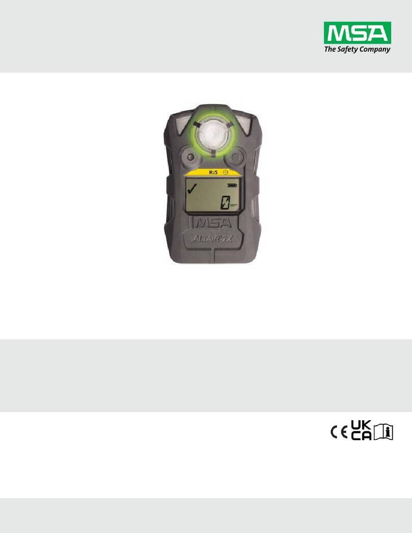
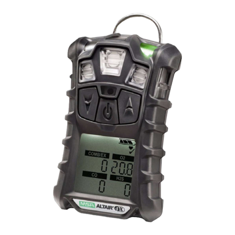
MSA altair 5 User manual

ALTAIR®5 Multigas Detector and
ALTAIR®5 IR Multi Gas Detector
Instruction Manual
Détecteur multigaz ALTAIR®5et
Détecteur multigaz ALTAIR®5 IR
Manuel d'utilisation
Detector Multigases ALTAIR®5 y
Detector Multigases ALTAIR®5 IR
Manual de funcionamiento
In North America, to contact your nearest stocking location, dial toll-free 1-800-MSA-2222
To contact MSA International, dial 1-412-967-3354 or 1-800-MSA-7777.
© MINE SAFETY APPLIANCES COMPANY 2009 - All Rights Reserved
This manual is available on the internet at www.msanet.com
En Amérique du Nord, pour contacter notre dépôt le plus proche, composez le numéro gratuit 1-800-
MSA-2222. Pour contacter MSA International, composez le 1-412-967-3354 ou le 1-800-MSA-7777.
© MINE SAFETY APPLIANCES COMPANY 2009 - Tous droits réservés
Ce manuel est disponible sur l’Internet au www.msanet.com
Para comunicarse con su localización de aprovisionamiento más cercana en América del Norte,
llame sin tarifa al 1-800-MSA-2222. Para comunicarse con MSA International, marque el 1-412-967-
3354 ó 1-800-MSA-7777.
© MINE SAFETY APPLIANCES COMPANY 2009 - Se reservan todos los derechos
Este manual puede obtenerse en la Internet en el sitio: www.msanet.com
Manufactured by/Fabriqué par/Fabricado por
MSA NORTH AMERICA
P.O. Box 427, Pittsburgh, Pennsylvania 15230
(L) Rev 2 10094176

ALTAIR®5
Multigas Detector and
ALTAIR®5 IR
Multi Gas Detector
Instruction Manual
In North America, to contact your nearest stocking location, dial toll-free 1-800-MSA-2222
To contact MSA International, dial 1-412-967-3354 or 1-800-MSA-7777.
© MINE SAFETY APPLIANCES COMPANY 2009 - All Rights Reserved
This manual is available on the internet at www.msanet.com
Manufactured by
MSA NORTH AMERICA
P.O. Box 427, Pittsburgh, Pennsylvania 15230
(L) Rev 2 10094176

THIS MANUAL MUST BE CAREFULLY READ BY ALL INDIVIDUALS WHO HAVE OR WILL
HAVE THE RESPONSIBILITY FOR USING OR SERVICING THE PRODUCT. Like any piece
of complex equipment, this instrument will perform as designed only if it is used and serv-
iced in accordance with the manufacturer’s instructions. OTHERWISE, IT COULD FAIL TO
PERFORM AS DESIGNED AND PERSONS WHO RELY ON THIS PRODUCT FOR THEIR
SAFETY COULD SUSTAIN SEVERE PERSONAL INJURY OR DEATH.
The warranties made by Mine Safety Appliances Company with respect to the product are
voided if the product is not used and serviced in accordance with the instructions in this
manual. Please protect yourself and others by following them. We encourage our cus-
tomers to write or call regarding this equipment prior to use or for any additional infor-
mation relative to use or repairs.
"! WARNING

Table of Contents
1. Instrument Safety . . . . . . . . . . . . . . . . . . . .1-1
1.1. Correct Use . . . . . . . . . . . . . . . . . . . . . . . . . . . . . .1-1
1.2. Safety and Precautionary Measures . . . . . . . . . . .1-2
1.3. Warranty . . . . . . . . . . . . . . . . . . . . . . . . . . . . . . . . .1-5
1.3.1 Warranty . . . . . . . . . . . . . . . . . . . . . . . . . . . . . . .1-5
1.3.2 Exclusive Remedy . . . . . . . . . . . . . . . . . . . . . . .1-6
1.3.3 Exclusion of Consequential Damage . . . . . . . .1-6
2. Description . . . . . . . . . . . . . . . . . . . . . . . . .2-1
2.1. Instrument Overview. . . . . . . . . . . . . . . . . . . . . . . . .2-1
Figure 2-1. Instrument View . . . . . . . . . . . . . . . . . . .2-1
2.2 User Interfaces . . . . . . . . . . . . . . . . . . . . . . . . . . . . .2-2
2.2.1 Button Definitions . . . . . . . . . . . . . . . . . . . . . . . .2-2
2.2.2 LED Definitions . . . . . . . . . . . . . . . . . . . . . . . . . .2-3
2.2.3 Alarms . . . . . . . . . . . . . . . . . . . . . . . . . . . . . . . . .2-3
2.3.3.1 Vibrating Alarm . . . . . . . . . . . . . . . . . . . . . . . .2-3
2.2.3.2 Horn . . . . . . . . . . . . . . . . . . . . . . . . . . . . . . . . .2-3
2.3.3.3 InstantAlert™ Alarm . . . . . . . . . . . . . . . . . . . . .2-3
2.3.3.4 Motion Alert Alarm . . . . . . . . . . . . . . . . . . . . . .2-3
2.2.3.5 Stealth Mode . . . . . . . . . . . . . . . . . . . . . . . . . .2-4
2.2.4 Backlight . . . . . . . . . . . . . . . . . . . . . . . . . . . . . . .2-4
2.2.5 Confirmation Beep . . . . . . . . . . . . . . . . . . . . . . .2-4
2.3. On-Screen Indicators . . . . . . . . . . . . . . . . . . . . . . .2-5
2.3.1 Monochrome Display . . . . . . . . . . . . . . . . . . . . .2-5
Figure 2-2. Monochrome Display . . . . . . . . . . . . . . .2-5
2.3.2 Color Display . . . . . . . . . . . . . . . . . . . . . . . . . . .2-6
2.3.2.1 Wireless-Equipped Units . . . . . . . . . . . . . . . . .2-6
2.3.3 Battery Life Indicator . . . . . . . . . . . . . . . . . . . . . .2-6
Figure 2-3. Color Display . . . . . . . . . . . . . . . . . . . . .2-6
Figure 2-4. Battery Warning . . . . . . . . . . . . . . . . . . .2-7
2.3.4 Battery Charging . . . . . . . . . . . . . . . . . . . . . . . . .2-8
Figure 2-5. Battery Shut Down . . . . . . . . . . . . . . . .2-8
2.4. Viewing Additional Pages . . . . . . . . . . . . . . . . . . . .2-9
2.4.1 Peak Readings (PEAK page) . . . . . . . . . . . . . .2-10
2.4.2 Minimum Readings (MIN page) . . . . . . . . . . . .2-10
i

2.4.3 Short Term Exposure Limits (STEL page) . . . .2-11
2.4.4 Time Weighted Average (TWA Page) . . . . . . . .2-12
2.4.5 Date Display . . . . . . . . . . . . . . . . . . . . . . . . . . .2-13
2.4.6 Last Cal Page . . . . . . . . . . . . . . . . . . . . . . . . . .2-13
2.4.7 Cal Due Page . . . . . . . . . . . . . . . . . . . . . . . . . .2-13
2.4.8 Motion Alert Activation Page . . . . . . . . . . . . . . .2-13
2.5 Sensor Missing Alarm . . . . . . . . . . . . . . . . . . . . . .2-13
2.6 Monitoring Toxic Gases . . . . . . . . . . . . . . . . . . . . .2-14
2.7 Monitoring Oxygen Concentration . . . . . . . . . . . . .2-15
Figure 2-6. Alarm Conditions (High Alarm shown) 2-15
2.8. Monitoring Combustible Gases . . . . . . . . . . . . . . .2-16
3. Operation . . . . . . . . . . . . . . . . . . . . . . . . . . .3-1
3.1. Environmental Factors . . . . . . . . . . . . . . . . . . . . . .3-1
3.2. Turning ON and Fresh Air Setup . . . . . . . . . . . . . . .3-1
3.2.1 Sampling Safety Test . . . . . . . . . . . . . . . . . . . . .3-3
3.2.2 Fresh Air Setup (FAS) . . . . . . . . . . . . . . . . . . . . .3-3
Figure 3-1. Fresh Air Setup . . . . . . . . . . . . . . . . . . .3-4
3.3. Measurement Mode (Normal Operation) . . . . . . . .3-5
3.4 Instrument Setup . . . . . . . . . . . . . . . . . . . . . . . . . . .3-5
3.4.1 Calibration Options . . . . . . . . . . . . . . . . . . . . . . .3-6
Figure 3-2. Password Screens . . . . . . . . . . . . . . . .3-6
Figure 3-3. Calibration Options . . . . . . . . . . . . . . . .3-6
3.4.2 Alarm Options . . . . . . . . . . . . . . . . . . . . . . . . . . .3-8
Figure 3-4. Alarm Options . . . . . . . . . . . . . . . . . . . .3-8
Figure 3-5. Sensor Alarm Setup . . . . . . . . . . . . . .3-10
Figure 3-6. Sensor Alarm Setup . . . . . . . . . . . . . .3-10
3.4.3 Instrument Options . . . . . . . . . . . . . . . . . . . . . .3-11
Figure 3-7. Instrument Options . . . . . . . . . . . . . . .3-11
Figure 3-8. Sensor Options . . . . . . . . . . . . . . . . . .3-12
3.5. MSA Link Operation . . . . . . . . . . . . . . . . . . . . . . .3-14
3.6. Function Tests on the Instrument . . . . . . . . . . . . .3-14
3.7. Calibration Check . . . . . . . . . . . . . . . . . . . . . . . . .3-14
3.8. Calibration . . . . . . . . . . . . . . . . . . . . . . . . . . . . . . .3-15
3.8.1 Zero Calibration . . . . . . . . . . . . . . . . . . . . . . . .3-16
3.8.2 Span Calibration . . . . . . . . . . . . . . . . . . . . . . . .3-17
3.8.3 Finishing Calibration . . . . . . . . . . . . . . . . . . . . .3-19
3.8.4 Calibration Failure . . . . . . . . . . . . . . . . . . . . . . .3-19
ii
3.8.5 Calibration with GALAXY Test System . . . . . . .3-19
3.9 Instrument Shutdown . . . . . . . . . . . . . . . . . . . . . . .3-20
Figure 3-9. Instrument Shutdown . . . . . . . . . . . . .3-20
4. Maintenance . . . . . . . . . . . . . . . . . . . . . . . .4-1
4.1 Troubleshooting . . . . . . . . . . . . . . . . . . . . . . . . . . . .4-2
4.2 Verifying Pump Operation . . . . . . . . . . . . . . . . . . . .4-2
4.3 Replacing the Battery . . . . . . . . . . . . . . . . . . . . . . . .4-4
Figure 4-1. Battery Replacement . . . . . . . . . . . . . . .4-4
Figure 4-2. Battery Replacement . . . . . . . . . . . . . . .4-4
4.4 Live Maintenance Procedure-
Replacing or Adding a Sensor . . . . . . . . . . . . . . . . . . . .4-5
Figure 4-3. Sensor Replacement . . . . . . . . . . . . . . .4-6
4.5. Replacing the Filter
(for instruments with integral pump) . . . . . . . . . . . . . . . .4-7
4.6. Cleaning the Instrument . . . . . . . . . . . . . . . . . . . . .4-7
4.7 Storage . . . . . . . . . . . . . . . . . . . . . . . . . . . . . . . . . . .4-8
4.8. Shipment . . . . . . . . . . . . . . . . . . . . . . . . . . . . . . . . .4-8
5. Technical Specifications/Certifications . .5-1
5.1 Technical Specifications . . . . . . . . . . . . . . . . . . . . .5-1
5.2 Factory-set Alarm Thresholds . . . . . . . . . . . . . . . . .5-2
5.3 Sensor Performance Specifications . . . . . . . . . . . . .5-3
5.4 Calibration Specification . . . . . . . . . . . . . . . . . . . . . .5-5
5.5 Certifications . . . . . . . . . . . . . . . . . . . . . . . . . . . . . . .5-6
5.6 Combustible Gas Cross Reference Factors . . . . . .5-7
6. Order Information . . . . . . . . . . . . . . . . . . .6-1
6.1 Gas Cylinder Parts List . . . . . . . . . . . . . . . . . . . . . .6-1
6.2 Accessories Parts List . . . . . . . . . . . . . . . . . . . . . . .6-2
6.3 Instrument Replacement Parts . . . . . . . . . . . . . . . . .6-3
7. Appendix – Flow Charts . . . . . . . . . . . . . . .7-1
7.1. Start Up Sequence (Power ON) . . . . . . . . . . . . . . .7-1
7.2. Normal Operation . . . . . . . . . . . . . . . . . . . . . . . . . .7-2
7.3. Options from Main Page . . . . . . . . . . . . . . . . . . . . .7-3
iii

7.4. Password Protected Options . . . . . . . . . . . . . . . . . .7-4
7.5. Menu Sequence from Main page . . . . . . . . . . . . . .7-5
7.6. Calibration Sequence . . . . . . . . . . . . . . . . . . . . . . .7-7
7.7. Calibration Options . . . . . . . . . . . . . . . . . . . . . . . . .7-8
7.8. Alarm Options . . . . . . . . . . . . . . . . . . . . . . . . . . . . .7-9
7.8.1 Sensor Alarm Options . . . . . . . . . . . . . . . . . . . .7-10
7.9. Instrument Options . . . . . . . . . . . . . . . . . . . . . . . .7-11
iv

1-1
1. Instrument Safety
1.1. Correct Use
The ALTAIR 5 and ALTAIR 5 IR Multigas Detectors are for use by
trained and qualified personnel. They are designed to be used when
performing a hazard assessment to:
• Assess potential worker exposure to combustible and toxic gases
and vapors as well as low level of oxygen.
• Determine the appropriate gas and vapor monitoring needed for a
workplace.
The ALTAIR 5 and ALTAIR 5 IR Multigas Detectors can be equipped
to detect up to five gases in the ALTAIR 5 and up to six gases in the
ALTAIR 5 IR:
• Combustible gases and certain combustible vapors
• Oxygen-deficient or oxygen-rich atmospheres
• Specific toxic gases for which a sensor is installed.
While the instrument can detect up to 25 % oxygen in ambient air, it is
approved for use only up to 21 % oxygen.
The ALTAIR 5 IR Gas Detector contains one Infrared sensor to detect
either CO2or specific combustible gases up to 100% volume, in
addition to up to five other gases.
Read and follow all instructions carefully.
• Perform a blocked flow test before each day's use if
equipped with an integral pump.
• Check calibration before each day's use and adjust if
necessary.
• Check calibration more frequently if exposed to silicone,
silicates, lead-containing compounds, hydrogen sulfide, or
high contaminant levels.
• Recheck calibration if unit is subjected to physical shock.
• Use only to detect gases/vapors for which a sensor is
installed.
• Do not use to detect combustible dusts or mists.
"WARNING

• Make sure adequate oxygen is present.
• Never block sensors.
• Never block pump inlet, except to perform sampling
safety test.
• Have a trained and qualified person interpret instrument
readings.
• Do not remove battery pack from instrument while in a
hazardous location.
• Do not recharge Li Ion battery in a hazardous location.
Risk of explosion may occur.
• Do not replace alkaline batteries in a hazardous location.
• Do not alter or modify instrument.
• Use only MSA-approved sampling lines.
• Do not use silicone tubing or sampling lines.
• Wait sufficient time for the reading; response times vary,
based on gas and length of sampling line.
• Do not use the instrument with integral pump for
prolonged periods in an atmosphere containing a
concentration of fuel or solvent vapors that may be
greater than 10%LEL.
INCORRECT USE CAN CAUSE SERIOUS PERSONAL INJURY OR DEATH.
This Class A digital apparatus complies with Canadian ICES-003.
For users in Australia/ New Zealand: The charge cradle is a Class A
product. In a domestic environment, this product may cause radio
interference, in which case, the user may be required to take adequate
measures.
1.2. Safety and Precautionary Measures
Carefully review the following safety limitations and
precautions before placing this instrument in service.
Incorrect use can cause serious personal injury or death.
The Altair 5 Multigas Detector is designed to:
• Detect gases and vapors in air only
"WARNING
1-2

• Detect only specified toxic gases for which a sensor is installed.
(for available sensors,see Section 5.3)
• Perform a blocked flow test (see section 4.2) before each day's
use if equipped with an integral pump.
• MSA recommends to check the instrument's functionality
(see section 3.6) and carry out a routine inspection each day
before use.
• Perform calibration check (see section 3.7) before each day's use
to verify proper instrument operation. Adjust calibration if the
readings are not within the specified limits.
• Check calibration more frequently if unit is subjected to physical
shock or high levels of contaminants. Also, check calibration more
frequently if the tested atmosphere contains the following
materials, which may desensitize the combustible gas sensor and
reduce its readings:
• Organic silicones
• Silicates
• Lead-containing compounds
• Hydrogen sulfide exposures over 200 ppm or exposures over
50 ppm for one minute.
The minimum concentration of a combustible gas in air that can ignite is
defined as the Lower Explosive Limit (LEL). A combustible gas reading
of "100” or "5.00” indicates the atmosphere is above 100 % LEL or 5.00
%vol CH4, and an explosion hazard exists. Move away from hazardous
area immediately.
Do not use the ALTAIR 5 or ALTAIR 5 IR Multigas Detectors to test for
combustible or toxic gases in the following atmospheres as this may
result in erroneous readings:
• Oxygen-deficient or oxygen-rich atmospheres
• Reducing atmospheres
• Furnace stacks
• Inert environments (only IR sensors acceptable for use)
• Atmospheres containing combustible airborne mists/dusts.
Do not use the ALTAIR 5 or ALTAIR 5 IR Multigas Detectors to test for
combustible gases in atmospheres containing vapors from liquids with a
high flash point (above 38 °C, 100°F) as this may result in erroneously
low readings.
1-3

Do not block sensor openings as this may cause inaccurate readings.
Do not press on the face of the sensors, as this may damage them and
cause erroneous readings. Do not use compressed air to clean the
sensor holes, as the pressure may damage the sensors.
Allow sufficient time for unit to display accurate reading. Response
times vary based on the type of sensor being utilized (see Section 5.3,
"Sensor Performance Specifications"). For units with a sample pump,
allow a minimum of 1 second per foot (3 seconds per meter) of sample
line to allow the sample to be drawn through the sensors.
Sampling lines made from 0.062 inch (1.57 mm) inner diameter tubing
provide fast transport times to the instrument; however, they must be
limited to 50 feet (15 m) in length.
Sampling of reactive toxic gases (Cl2, ClO2, NH3) must only be done
with the reactive gas sample line and probe kits listed in the
Accessories table in Section 6.2.
All instrument readings and information must be interpreted by
someone trained and qualified in interpreting instrument readings in
relation to the specific environment, industrial practice and exposure
limitations.
Observe proper battery maintenance
Use only battery chargers made available by MSA for use with this
instrument; other chargers may damage the battery pack and the
instrument. Dispose of in accordance with local health and safety
regulations.
Be aware of environmental conditions
A number of environmental factors may affect the oxygen and toxic
sensor readings, including changes in pressure, humidity and
temperature. Pressure and humidity changes affect the amount of
oxygen actually present in the atmosphere.
After exposure to negative (°C) temperatures, units with HCN (hydrogen
cyanide) sensors should be bump checked and calibrated, if necessary,
after returning to room temperature.
Be aware of the procedures for handling electrostatically sensitive
electronics
The instrument contains electrostatically sensitive components. Do not
open or repair the unit without using appropriate electrostatic discharge
(ESD) protection. The warranty does not cover damage caused by
electrostatic discharges.
1-4

Be aware of the product regulations
Follow all relevant national regulations applicable in the country of use.
Be aware of the warranty regulations
The warranties made by Mine Safety Appliances Company with respect
to the product are voided if the product is not used and maintained in
accordance with the instructions in this manual. Please protect yourself
and others by following them. We encourage our customers to write or
call regarding this equipment prior to use or for any additional
information relative to use or service.
1.3. Warranty
ITEM WARRANTY PERIOD
Chassis and electronics Two years*
COMB, O2, H2S, CO sensors Two years*
Cl2, ClO2, NH3, HCN, NO2, PH3, SO2sensors One year*
Infrared Sensor Two years*
*For extended warranty offerings please contact MSA
1.3.1 Warranty
This warranty does not cover filters, fuses, etc. Certain other
accessories not specifically listed here may have different warranty
periods. This warranty is valid only if the product is maintained and
used in accordance with Seller's instructions and/or recommendations.
The Seller shall be released from all obligations under this warranty in
the event repairs or modifications are made by persons other than its
own or authorized service personnel or if the warranty claim results from
physical abuse or misuse of the product. No agent, employee or
representative of the Seller has any authority to bind the Seller to any
affirmation, representation or warranty concerning this product. Seller
makes no warranty concerning components or accessories not
manufactured by the Seller, but will pass on to the Purchaser all
warranties of manufacturers of such components.
THIS WARRANTY IS IN LIEU OF ALL OTHER WARRANTIES,
EXPRESSED, IMPLIED OR STATUTORY, AND IS STRICTLY LIMITED
TO THE TERMS HEREOF. SELLER SPECIFICALLY DISCLAIMS ANY
WARRANTY OF MERCHANTABILITY OR OF FITNESS FOR A
PARTICULAR PURPOSE.
1-5

1.3.2 Exclusive Remedy
It is expressly agreed that Purchaser's sole and exclusive remedy for
breach of the above warranty, for any tortious conduct of Seller, or for
any other cause of action, shall be the replacement at Seller's option, of
any equipment or parts thereof, which after examination by Seller is
proven to be defective.
Replacement equipment and/or parts will be provided at no cost to
Purchaser, F.O.B. Seller's Plant. Failure of Seller to successfully replace
any nonconforming equipment or parts shall not cause the remedy
established hereby to fail of its essential purpose.
1.3.3 Exclusion of Consequential Damage
Purchaser specifically understands and agrees that under no
circumstances will seller be liable to purchaser for economic, special,
incidental or consequential damages or losses of any kind whatsoever,
including but not limited to, loss of anticipated profits and any other loss
caused by reason of nonoperation of the goods. This exclusion is
applicable to claims for breach of warranty, tortious conduct or any other
cause of action against seller.
1-6

2. Description
2.1. Instrument Overview.
1 LEDs (2 red "Alarm", 1 green "Safe") 9 ▼ Button
2 MSA LINK Communication 10 Belt Clip (Altair 5 only)
3 Sensor Inlets (Diffusion version) 11 Charging Port
4 Pump Cap (Pump version) 12 Screws
5 Horn 13 Pump inlet
6 Display 14 Filter
7 ▲ Button 15 Charge Status LED
8 Button
The instrument monitors gases in ambient air and in the workplace.
The ALTAIR 5 is available with a maximum of four sensors, which can
display readings for five separate gases (one Dual Toxic Sensor
provides both CO and H2S sensing capabilities in a single package).
The detector is available in a diffusion or pumped configuration. When
using the pumped instrument, do not remove the pump cap
(item 4 on FIGURE 2-1).
Figure 2-1. Instrument View
2-1

The ALTAIR 5 IR is available with a maximum of five sensors, which
can display readings for six separate gases (one Dual Toxic Sensor
provides both CO and H2S sensing capabilities in a single package).
The ALTAIR 5 and ALTAIR 5 IR Detectors are available with either a
monochrome or color display.
While the instrument can detect up to 25 % oxygen in ambient air, it is
approved for use only up to 21 % oxygen.
The alarm levels for the individual gases are factory-set but can be
changed through the instrument Setup Menu. These changes can also
be made through MSA LinkTM Software. Ensure that the latest version of
the MSA Link software has been downloaded from MSA’s website
www.msanet.com. It is recommended that after making changes using
MSA Link, the unit should be turned OFF and ON.
2.2 User Interfaces
Instrument operation is dialog driven from the display with the aid of the
three function buttons (see FIGURE 2-1).
2.2.1 Button Definitions
The ALTAIR 5 and ALTAIR 5 IR units use three buttons for user
operation. Each button can function as a "soft key", as defined
immediately above the button.
BUTTON DESCRIPTION
The Button is used to turn instrument ON or OFF and to confirm
user action selections.
▼ The ▼ Button is used to page down through data screens or to
decrease the values in Setup mode.
▲ The ▲ button is used to reset peak, STEL TWA and alarms
(where possible) or perform calibration in measuring mode. It is also used
as page up or to increase the values in Setup mode.
When the ▲ button and the ▼ button are pressed simultaneously while
in normal measure mode, the Setup Mode can be entered after the
Password is confirmed.
2-2

2-3
2.2.2 LED Definitions
LED DESCRIPTION
RED The Alarm LEDs are visual indications of an alarm condition or any type of
(ALARM) error in the instrument
GREEN The Safe LED flashes once every 15 seconds to notify the user that the
(SAFE) instrument is ON and operating under the conditions defined below:
• The green SAFE LED is enabled
• Combustible reading is 0% LEL or 0% VOL
• Oxygen (O2) reading is 20.8%
• All other sensor readings are 0 ppm
• No gas alarms are present (low or high)
• Instrument is not in Low Battery warning or alarm
• STEL and TWA readings are 0 ppm.
This option can be turned OFF through the MSA Link software
2.2.3 Alarms
The instrument is equipped with multiple alarms for increased user
safety:
2.3.3.1 Vibrating Alarm
The instrument vibrates when any alarm condition is active. This can be
turned OFF through the SETUP- ALARM OPTIONS menu
(Section 3.4.2).
2.2.3.2 Horn
This unit is equipped with an audible alarm. The horn can be turned
OFF through the SETUP- ALARM OPTIONS menu (Section 3.4.2).
2.3.3.3 InstantAlert™ Alarm
The InstantAlert exclusive feature allows the user to manually activate
an audible alarm to alert those nearby to potentially dangerous
situations. Holding the ▼ button for approximately 5 seconds while in
Normal Measure Mode activates the InstantAlert alarm.
2.3.3.4 Motion Alert Alarm
If Motion Alert is turned ON (+= ON) and activated (see Section 3.4.2),
the instrument activates a "Man Down" alarm if motion is not detected
within 30 seconds. The Alarm LEDs flash, and the horn activates with
an increasing audible frequency.

2.2.3.5 Stealth Mode
Stealth Mode disables the visual, audible and vibrating alarms. MSA
recommends that this feature be left in its default "OFF" state. This can
be turned ON through the SETUP - INSTRUMENT OPTIONS menu
(Section 3.4.3).
The message "Alarms OFF" flashes on the monochrome display when
Stealth mode is ON. On the color display, all three alarm icons are
shown as OFF ( )
2.2.4 Backlight
The backlight automatically activates when any front panel button is
pressed and remains ON for the duration of user-selected timeout. This
duration can be changed using the Setup- Instrument Mode (Section
3.4.3) or through MSA Link software.
2.2.5 Confirmation Beep
This confirmation beep activates every 30 seconds by momentarily
beeping the horn and flashing the alarm LEDs under the following
conditions:
• Confirmation beep is enabled
• Instrument is on normal Measure Gases page
• Instrument is not in battery warning
• Instrument is not in gas alarm.
2-4

2-5
2.3. On-Screen Indicators
2.3.1 Monochrome Display
1 Gas Type 5 Battery Condition
2 Current Time 6 Motion Alert ON or Successful Cal Indicator
3 "Soft Key" ▼ Indicator 7 "Soft Key" ▲ Indicator
4 Gas Concentration
Combustible sensor reading
Oxygen sensor reading
CO sensor reading
H2S sensor reading
Toxic (fifth) sensor reading if installed
Indicates the name of next page
Initiates Calibration
IR Sensor - 6th sensor if installed
On a monochrome display, a message appears every 30 seconds
if the Vibration, Horn or LED alarms are turned OFF.
Figure 2-2. Monochrome Display
CAL
METH

2.3.2 Color Display
1 "Soft Key" ▼ Indicator 8 Vibration Alarm OFF
2 Gas Numeric Value 9 Horn OFF
3 Gas Concentration Units 10 LED OFF
4 Current Time 11 Battery Condition
5 Motion Alert (+ = ON) 12 Gas Type
6 Wireless ON 13 "Soft Key" ▲ Indicator
7 Combustible Gas type calibration
2.3.2.1 Wireless-Equipped Units
Color display units can be ordered with a wireless capability that allows
communication with the alphaScout Personal Network. This Network
capability is almost exclusively used in International markets. Contact
MSA for additional information.
2.3.3 Battery Life Indicator
The battery condition icon continuously displays in the upper right-hand
corner of the color display and in the lower right-hand corner of the
monochrome display. A bar represents the charging level of the battery.
The nominal run-time of the instrument (COMB, O2, H2S, CO, with
pump and monochrome display) at room temperature is 14 hours.
Actual run-time varies, depending on ambient temperature and alarm
conditions.
Figure 2-3. Color Display
2-6

Low Battery Warning
If battery warning alarm activates while using the
instrument, leave the area immediately as the end of
battery life is approaching. Failure to follow this
warning can result in serious personal injury or death.
The battery icon blinks when battery life is nearly expired. The Alarm
LEDs flash once per minute under this condition.
The duration of remaining instrument operation during the low battery
warning depends on ambient temperatures, battery condition and
alarm status.
When the instrument goes into battery warning the:
• battery life indicator continuously blinks
• alarm sounds and alarm LEDs flash once per minute
• Safe LEDs no longer flash
• instrument continues to operate until it is turned OFF or battery
shutdown occurs
Figure 2-4. Battery Warning
"WARNING
2-7
Other manuals for altair 5
5
This manual suits for next models
1
Table of contents
Languages:
Other MSA Gas Detector manuals

MSA
MSA DF-8500 C User manual

MSA
MSA ORION User manual

MSA
MSA 47K Series User manual

MSA
MSA GTYQ-DF-8500 C User manual

MSA
MSA SMC 5100-IT Series User manual

MSA
MSA General Monitors OBSERVER-i User manual

MSA
MSA PrimaX User manual

MSA
MSA General Monitors OBSERVER-i User manual

MSA
MSA ALTAIR4 Technical manual

MSA
MSA TG5000 User manual