Uniphos FumiSense Pro UNIPHOS-250 User manual

UNIPHOS-250(PM)
FumiSense Pro
INSTRUCTION MANUAL
Uniphos Envirotronic Pvt. Ltd.
Readymoney Terrace, 167,
Dr. Annie Besant Road,
Worli, Mumbai –400018, India.
Tel: (91-22) 2493 0681, Fax: 2493 8826

2
Dear Customer,
Congratulations on your purchase of UNIPHOS-250(PM) FumiSense Pro. This monitor has
been produced using the state of the art Technology by our company Uniphos Envirotronic
Pvt. Ltd. at Vapi, to provide you an instrument with the best of features and yet at a
moderate cost. It represents the high degree of craftsmanship and reliability that has
made UNIPHOS a leader in the field of gas detection.
Please read the instruction manual carefully. It gives a brief description of the instrument
and the full details of operation for measurement, calibration, parameter setting etc. To
ensure a long trouble free performance, please take due care and ensure proper
maintenance of your monitor as recommended in this Instruction manual.
Please do not attempt to use any other accessories and other components other than
UNIPHOS. Also do not attempt to open the instrument at site, as it would lead to
termination of warranty for your instrument. If you have any queries regarding the
operation or maintenance of your UNIPHOS monitor, please do feel free to consult our
factory at the address on the front cover or contact the service representative for your
area and we will be happy to help you.

3
Table of content
Sr. No
Content
Page
No
1
INTRODUCTION
4
1.1
WORKING PRINCIPLE
4
2
INSTRUMENT DESCRIPTION
5
2.1
FRONT PANEL
5
2.2
LEFT HAND SIDE PANEL
7
2.3
BOTTOM PANEL(fig 3)
8
3
INSTRUMENT OPERATION
9
3.1
INITIALIZATION
9
4
OPERATION IN VARIOUS MODES
10
4.1
PARAMETER SETTING MODE
10
4.1.1
SELECT SAMPLING TYPE & SAMPLING TIME
10
4.1.2
SET SERIAL NUMBER
11
4.1.3
DATE TIME SETTING
11
4.2
CALIBRATION MODE
11
4.2.1
CALIBRATION PROCESS
11
4.3
SAMPLING MODE
12
4.4
DATA DOWNLAODING MODE
14
4.4.1
TO DOWNLOAD RANGE OF REPORTS
14
4.4.2
To DOWNLOAD SUMMARY REPORT
15
5
HOW TO MONITOR BATTERY CHARGE LEVEL
16
6
INSTRUMENT SPECIFICATIONS
17
7
SENSOR SPECIFICATIONS
18
ANNEXURE 1
18
8
MAINTENANCE
19
9
TROUBLESHOOTING
20
10
CALIBRATION SCHEDULE
21
11
CONCLUSION/ REMARKS
22
12
NOTES
23
13 LIMITATION OF WARRANTY & LIABLITY 24

4
1. Introduction
Fumigation of stored products as a pest control measure is widely practiced all over the world.
Phosphine, Methyl Bromide (MBr) and Sulfuryl Fluoride (SO2F2) are some of the commonly
used fumigants.
Phosphine (PH3)in particular is a highly specific fumigant used to control number of pests in a
wide range of agricultural and horticultural crops and in wood products. Its primary application
is for quarantine treatment, soil fumigation and post harvest protection.
Fumigation is generally carried out by covering the commodities with a leak proof enclosure
and applying PH3of necessary concentration. Effective and scientifically carried out fumigation
procedure demands monitoring of the fumigation process during the entire period of fumigation.
For this application, UNIPHOS-250(PM) FumiSense Pro is suitable.
This manual gives the full description of the UNIPHOS-250(PM) FumiSense Pro, its operation,
calibration, maintenance and the other relevant information.
1.1 Working Principle
The UNIPHOS-250(PM) FumiSense Pro uses an electrochemical sensor for the detection of
Phosphine. When sensor encounters a target gas, current is generated in proportion to the gas
concentration. This current is converted into a voltage signal; it is digitized and displayed on the
instrument’s OLED display. This being a microprocessor-based instrument, it can continuously
monitor the Phosphine gas concentration and can store this data in its memory, which can be
later downloaded on a computer.
The instrument is powered by a 7.4 V Li-ion rechargeable battery.

5
2. Instrument Description
UNIPHOS-250(PM) FumiSense Pro is a microprocessor based instrument for the
measurement of Phosphine. Fig. 1 shows the front panel, Fig. 2 shows the right hand side
panel and Fig. 3 bottom panel of the instrument. The instrument has following important parts
namely sensor, signal conditioning electronics, alphanumeric OLED Display, a sample draw
pump and a battery pack.
Being a microprocessor based unit, it has data logging facility and can store the data with a
real time clock into the memory. There is also a provision to download the stored data on the
computer.
2.1 Front Panel
Fig. 1 Front Panel
The front panel of the instrument has
A. Four membrane keys, viz. UP▲, DN▼,SET ●&ENTER
B. Two Light Emitting Diodes (LED) namely, POWER and SAMPLING
C. And a Liquid Crystal Display (LCD/ OLED)
These are described as follows:
1. POWER LED:
This green LED glows, when the instrument is turned ON.
UP KEY (3)
DOWN KEY (4)
ENTER KEY (6)
POWER LED (1)
SAMPLING LED (2)
OLED (7)
SET KEY(5)

6
2. SAMPLING LED:
The sampling LED glows, when the instrument is in measurement mode.
3. UP KEY:
a) Menu page: Press this key to enter into the Sampling/Purging mode (either Batch or
continuous).
b) Parameter Set Mode: In this mode, the key is used to increase the value of the digit
below which the cursor is placed.
c) Calibration Mode: In this mode, the key is used as increment key.
d) Data downloading mode: Press this key to download all the stored data/records to the PC.
4. DOWN KEY:
a) Menu page: Press this key to enter into calibration mode.
b) Parameter Set Mode: In this mode, the key is used to move the cursor horizontally
over different digits.
c) Calibration Mode: In this mode, the key is used to shift the cursor.
d) Data downloading mode: In this mode, if DOWN key is pressed, all the stored data will be
deleted from the instrument’s memory.
∆CAUTION: One should be careful before pressing DOWN key in the Data
Downloading Mode, as the data logged so far into the internal memory of the instrument
will be lost permanently.
5. SET KEY:
a) Menu page: Press this key to enter into the Parameter Set Mode and to turn OFF the
instrument.
b) All other modes: Press this key to escape from the current page and to move over to the
next page.
6. ENTER KEY:
a) Menu page: Press this key to enter into the data downloading mode.
b) All other modes: To confirm the selection of mode and value of the parameter chosen or
to confirm the desired / selected operation.
7. OLED DISPLAY:
It is a 20 X 4 alphanumeric OLED display, which indicates
Various prompts during initialization process, immediately after turning ON the unit.
Gas concentration in the Measurement mode.
User settable parameters during Parameter Set mode.
Calibration data viz. zero –span counts during Calibration mode.
User friendly prompts during Sampling, Calibration, Data Downloading and other
Functions.

7
2.2 Left hand side panel
Fig. 2: Left hand side panel
The left hand side of the instrument contains a charging socket, a USB socket and two ports,
namely, Gas inlet nozzle & Gas outlet nozzle for sampling. These are marked on the instrument
for the identification. (Refer Fig. 2)
1. USB socket:
This socket is to interface the instrument with the computer. Monitor can be interfaced
with the PC for easy downloading of the data stored in the data logger. The other end is
to be connected to the COM port of the PC. The settings required for data downloading
are described in point 4.4 Data Downloading mode.
2. GAS INLET PORT:
Sampling tube is provided with the instrument to draw the gas from fumigation area. One
end the flexible tube is to be connected at the IN nozzle and other end to be inserted in
the fumigation area.
3. GAS OUTLET PORT:
One more flexible tube will be connected at the OUT nozzle to leave the sampled gas
back into the fumigation chamber.
USB (3)
INLET (1)
OUTLET (2)

8
2.3 Bottom panel
BATTERY CHARGER SOCKET:
This socket is provided for charging the instrument. Plug the charger to 110V/230VAC, 50-
60Hz power outlet and the other end to the instrument and turn it ON. Charge the battery for
3 - 4 hours. The Battery charge status can be viewed on the LCD/ OLED display in the
download page.

9
3. Instrument Operation
Press and hold the SET Key for 3-4 seconds to turn ON the instrument. A green LED marked
POWER on the front panel of the Instrument glows, confirming the same. Instrument can be
turned OFF by pressing set and confirming the turn OFF by ENTER key.
Note: Fully charge the unit before use. Charge the unit till RED Led on charger turns
GREEN, before using it for measurement.
3.1 INITIALIZATION
Once instrument is turned ON, it goes into the initialization and following prompts will appear
in the sequence on the display.
(Instrument Turn ON)
(Instrument Model and Serial number)
(Instrument software version)
(Range and Resolution, Current date and time)
(Last calibration date)
(Menu Page)
INSTRUMENT STARTS
IN
3 .. 2 .. 1 .. 0
SOFTWARE VERSION:
X.XX.XXX
RANGE: 0 - XXXX PPM
RESO. : XXX PPM
DATE: DD/MM/YY
TIME: HH:MM:SS
UP –SAMPLING
DN –CALIBRATE
SET –SETTINGS
ENT –DWNLD/RST
LAST CALIBRATION
DATE: DD/MM/YY
UNIPHOS-250
FUMISENSE PRO
SERIAL NUMBER
A-XXXX(PM)

10
At the end of the initialization, instrument moves to the menu page.
The menu page gives information on the operating mode selection for the specific key activation
as follows:
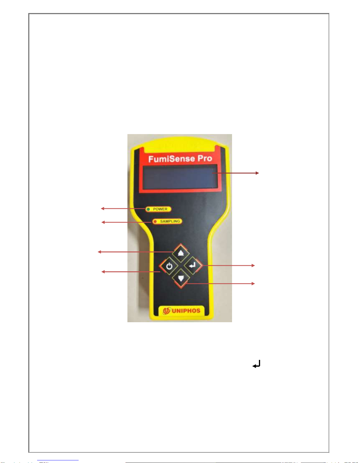
1. “UP” key ▲Monitoring mode i.e. Start sampling (continuous/batch sampling).
2. “DN” key ▼Switch to Calibration mode.
3. “SET” key ● Enter into parameter setting and to proceed for Instrument OFF page
4. “ENTER” key Access to data logger
4. Operations in Various Modes
4.1 PARAMETER SETTING MODE:
While in the menu page, press the SET Key ●to enter into the parameter set mode.
After successful authentication (Password - 123), user has an access to the following
parameters in this mode.
To change parameter value, follow below procedure.
1.The cursor will blink below the first digit of the Parameter. Use the DOWN Key ▼to move
the cursor horizontally over different digits (i.e. to change cursor position).
2. If any digit is to be changed, move the cursor under the digit and press the UP Key ▲.
Using the UP Key ▲, the digits can be changed from 0 to 9.
3. Press the ENTER Key to confirm the changed digit and to switch over to the next
parameter.
4. If the displayed parameter is not to be changed, press the SET Key ●to switch
over to the next parameter.
4.1.1 Select Sampling Type & Sampling Time:
1. In this screen, the cursor will blink below “C” of Continuous sampling type. Pressing the
DOWN Key, the cursor will toggle between “Continuous” and “Batch” sampling type.
Select the desired type. Press ENTER key to confirm the type and to move to the next
page.
2. In sampling time setting, the cursor will blink below the first digit of sampling time(only for
BATCH sampling)
As explained above in 4.1, user can input any desired sampling time (between 001-999)
by using UP/DN key and confirm the new value by pressing ENTER key.
Note: At any time, press SET to skip the current data (without saving) and to move to
the next screen.
Select sampling type
Continuous/Batch
Select sampling type
Continuous/Batch
Sampling Time
XXX Sec

11
4.1.2 Set Serial Number:
1. In this screen the display will show the current serial number of the instrument.
2. The cursor will be blinking at the first digit of the “Serial Number”, make desire changes
and press ENT key to confirm.
4.1.3 Date Time Setting:
In a similar way, one can change the Date & Time.
Note: If the displayed date & time or any of the above explained parameters are not to
be changed, one can press the SET Key ● to escape without altering the current values.
4.2 CALIBRATION MODE:
In the menu screen, press the DOWN Key ▼, the instrument moves to the calibration
mode. After Successful authentication (Password –321), the device is ready for
calibration.
Calibration of the instrument involves two steps:
1) Zeroing the instrument in clean air.
∆IMPORTANT: The instrument should be zeroed in clean air. If you are not sure
about the air quality, it is recommended to use the air from compressed clean air
cylinders available for the purpose.
2) Applying gas of known concentration, so that the reading matches with the calibration
gas concentration.
4.2.1 Calibration Process:
1. In the calibration mode, the first page is the Zero Calibration, “Apply Zero Gas”Prompt
will be displayed and instrument will take samples from air for 30 seconds, continuously
showing counts and remaining sampling time on display.
2. Instrument will be zeroed only if count value is in between 50 to 999.After zeroing
successfully ZERO CAL DONE prompt will appear otherwise ZERO CAL FAIL prompt
will be displayed.
Set Date:
DD/MM/YY
Set Time:
HH:MM:SS
Serial Number
A –XXXX (PM)

12
3. In case of ZERO CAL FAIL, exit from the calibration mode by pressing SET key. Again
re-enter into calibration mode and immediately after “APPLY ZERO GAS”prompt,
manually set zero count in between 50 to 999, ideally 500 by adjusting ZERO POT as
shown in the image below (within 30 seconds of zero calibration time).
4. After zeroing the instrument, following prompt will be displayed, enter the gas conc.
value for which instrument is to be calibrated.
5. Entering the gas value and by pressing enter key, “Apply Span Gas” prompt will
appear and instrument will take samples of target gas for 120 seconds and will show
counts value and remaining sampling time continuously.
Note: SPAN GAS VALUE should be equal to or in between 10 % to 80 % of full range
of the instrument, otherwise “INVALID SPAN GAS” prompt will appear on screen and
instrument will again ask for SPAN GAS VALUE.
6. Instrument will be calibrated only if counts value for applied span gas is in valid range
(i.e. From 2000 to 4030 display counts, ideally 3000).
7. After Span Calibration process, SPAN CAL DONE prompt will be displayed otherwise
SPAN CAL FAIL prompt will be displayed.
8. In case of SPAN CAL FAIL, re-enter into the calibration mode, zero the instrument
(optional in case of last successful zero calibration & can be skipped by pressing SET
key). Follow the same procedure mentioned from point 4 and set counts value between
range (as mentioned in point 6 of 4.2.1) by adjusting SPAN POT as shown in the image
below (within 120 seconds of span calibration time).
Upon successful Span calibration, Last calibration date of instrument will be updated
automatically to the current date.
4.3 SAMPLING MODE:
Before entering into the sampling mode, select the sampling type (Continuous/Batch
sampling) as described in section 4.1.1. Set the sampling time if batch sampling is selected
as the mode of operation.
Span Gas
XXXX
SPAN POT(TG1)
ZERO POT (TZ1)

13
1. Press UP key in the menu page to enter the sampling mode and following prompt will
appear on the screen.
2. Select Sampling or Purging as per the requirement using Up/Dn key. If the sampling is
selected, instrument will display following prompt.
3. On pressing Enter Key, instrument will enter in to zero check mode, will display for the
zero check and will proceed for sampling.
4. Connect tubes and press Enter key to enter into the sampling mode.
5. In continuous sampling mode, instrument will start taking sample until the SET key is
pressed to stop the sampling.
Note: In the continuous sampling mode, data can be logged by pressing ENTER key
during sampling.
6. In batch sampling mode, instrument will draw gas sample for the time period set in the
Sampling Time setting mode and continuously display the gas concentration on display
as shown below.
XXX
PH3: XXXX PPM
DATE TIME
Remove Tubes
Select:
Sampling/Purging
Tubes Removed?
Press Enter Key
Zero Check
Please Wait
Connect Tubes
Press Enter Key
CNT
PH3: XXXX PPM
DATE TIME

14
7. In batch sampling mode, once sampling is over, monitor prompts for data logging mode
as shown below.
8. Press the UP key and after asking for confirmation, enter site and location value and
press ENTER key to log the data in to the instruments memory or press SET key to
move to the Purging page without logging / storing the data.
9. Instrument will enter into main menu page once purging is over.
Note: Any time in the menu page, if zero is not in its acceptable range, it will display
sensor drift and instrument needs to be calibrated by following procedure described in
4.2.
4.4 DATA DOWNLOADING MODE:
1. In the menu page, when the ENTER key is pressed, instrument will enter into the data
downloading mode and the screen will appear as shown below.
On pressing UP Key, Complete summary or range of reports can be downloaded on
computer.
4.4.1 To download range of reports:
1. In data downloading mode, to print range of reports, select Report using UP/DN and
ENTER KEY in the data download page.
PH3: XXXX PPM
Press UP Key
to log data
UP - Download Data
DN - Erase Data
SET - Exit
ENT –Battery status
Remove Tubes
Press Enter Key
Download:
Summary/Report
Sensor
Drift
Please
Calibrate

15
2. Press Enter key to print the range of data to be printed.
Note: XXXX indicates the maximum no. of data that is present in the memory.
4.4.2 To Download Summary report:
1. In data downloading mode, to print summary report, select Summary using UP/DN
in the data download page.
2. On Confirming through Enter key, instrument will start printing records and will show
current record being printed on the display.
3. Instrument will return to main menu page once printing is over.
2. Connect instrument with computer via USB cable supplied for data downloading.
3. Create a New Connection on HyperTerminal
*HyperTerminal is bundled software for serial communication that is included in Microsoft
Windows 98and higher versions. It can be configured as follows:
1. Click the START button on the PC.
2. Go to Programs-> Accessories -> Communications -> HyperTerminal
3. A “New Connection – HyperTerminal” window will appear on the screen with the
“Connection Description” Dialog box.
4. In the “Name” Text Box, enter a name for connection (say ABC).
5. Click the OK Button.
6. After this the “Connect To” Dialog Box will appear on the screen.
7. In the “Connect to” Text Box, select “Direct to COM1/COM2” from the drop down
list.
8. Click the OK Button
9. On clicking OK, the “COM1 Properties” Dialog Box will pop up.
10. In the “Port Settings” Tab, set the parameters as given below:
Bits per second –9600
Data Bits -- 8
Parity -- None
Stop Bits -- 1
Flow Control -- None
Enter Report No
From: 0000
To : XXXX
Download:
Summary/Report
Downloading …
XXXX

16
11. Click the OK Button. A blinking cursor will now appear on the New Connection
(say ABC) Window.
4. Now the data in the memory of the equipment can be downloaded to the PC by pressing
UP key. The records will appear on the new connection window.
5. Press the DOWN key if the data from the instrument memory is to be erased.
6. Press SET key to escape from this page and to move to the main menu page
5. How to Monitor Battery Charge Level
The battery charge level can be viewed on the LCD/OLED panel when the instrument is in
main Data Downloading page.
The LCD/OLED will indicate the battery charge level in terms of %, below the battery prompt as
following.
Battery status can only be monitored when the instrument is in the Data downloading page.
When the battery capacity goes below 25%, the LOW BATTERY prompt will be displayed on
LCD/OLED and instrument will prompt the menu page only after charging the battery. Battery
should be charged for 2 to 3 Hours.
Battery
XXX %

17
6.Instrument Specifications
Sr. No.
Feature
Description
1
Gas sampling
Sample draw type
2
Display
20 X 4 Alphanumeric LCD/ OLED Display
3
Inbuilt pump
Flow rate: 500 - 1000 ml/min
Power: 4.5 V DC, 35 mAH
4
Power supply
Inbuilt 7.4 V Li-Ion rechargeable battery
5
Weight
0.57 Kg (1.256 lb)
6
Construction material
Hi Impact ABS Plastic
7
Standard accessories
Battery Charger, Data downloading cable and
dust filter

18
7. Sensor Specifications
Sr.No.
Feature
Description
1
Gas detected
Phosphine(PH3)
2
Detection principle
Electrochemical sensor
3
Concentration range
Annexure 1
4
Resolution
Annexure 1
5
Warm up time
Less than 1 min
6
Response time
Typically less than 60 sec
7
Accuracy
Inherently ± 2% (but also depends on the
accuracy of the calibrating gas)
8
Drift
Less than 2% of signal per month at constant
temperature and pressure.
9
Operating temperature
0 to + 40 oC
10
Operating pressure
Ambient ± 10%
11
Operating life of sensor
Expected life 1 –2 years
Warranted for one year.
NOTE: PH3sensors are warranted for ONE year.
Annexure 1
Sr.
No.
Gas Name
Model
Range
Resolution
Response
time(T90)
1
Phosphine
UNIPHOS-250(PM)
FumiSense Pro
0 –1000 PPM
1 PPM
60 Secs
2
0 –2000 PPM
1 PPM
60 Secs

19
8. Maintenance
1. DO a regular battery checkup and recharge it fully before use whenever the battery is low.
2. Perform the calibration check once in a month. Calibration check every month will ensure
the accuracy of readings throughout the life of the instrument.
3. NEVER allow the unit to be used in direct sunlight. You may provide the canopy/sun shade
while using the instrument on the site.
4. ZERO it in a target gas-free clean air.
5. NEVER expose the sensor to gas concentration higher than its prescribed range.
6. DO NOT expose the monitor to excessive positive or negative pressure. It affects the
accuracy of the measurement.
7. Occasionally, the casing of the instrument can be cleaned with a slightly damp lint free
cloth. Wipe the instrument thoroughly dry using a fresh lint free cloth. But care should be
taken not to allow any water or moisture to enter the instrument.
8. Do not keep the monitor without use, for more than 3 months (from the date of
shipment). Li-Ion battery performance may get affected.

20
9. Troubleshooting
Problem
Possible cause
Solution to the problem
The instrument does not turn ON
Low Battery
Recharge battery
Pump making abnormal noise
There may be blockage in
the gas sampling tube or
in the nozzles
Clear blockage
This manual suits for next models
1
Table of contents
Other Uniphos Gas Detector manuals