Osaka F1 User manual
OSAKA –F 1–User’s Manual –v1 –PAG. 1
USER’S MANUAL FOR COOL/HEAT
DIGITAL THERMOSTAT WITH
DEFROSTING
User’s Manual –v1
www.osakasolutions.com
INTRODUCTION
in this manual there is the necessary
information for the proper installation and
usage instruction and maintenance of the
product, it is recommended to read it carefully
and to keep it.
In order to avoid dangerous or hazardous
circumstances for people, things or animals due to an
irregular operation or the malfunctioning of the thermostat, we
remind you that the installation must comply with and be
aware of the annexed safety systems, necessary to guarantee
the aforementioned safety.
Neither OSAKA SOLUTIONS nor its legal representatives are
responsible neither for the inadequate use of the
THERMOSTAT nor for the use of it not conforming to the
characteristics of the THERMOSTAT.
INDEX
1
DESCRIPTION OF THE CONTROLLER
1.1
GENERAL DESCRIPTION
1.2
FRONT PANEL DESCRIPTION
2
PROGRAMMING
2.1
QUICK SELECTION OF THE SET POINT
2.2
STANDARD PROGRAMMING OF THE PARAMETERS
2.3
2.4
PARAMETERS PROTECTION THROUGH PASSWORD
CUSTOMIZING PARAMETERS WITH / WITHOUT
PASSWORD
2.5
RESTORATION OF INITIAL PARAMETERS
2.6
KEYBOARD LOCKING FUNCTION
3
USAGE AND INSTALLATION WARNINGS
3.1
USAGE WARNING
3.2
MECHANICAL ASSEMBLING
3.3
ELECTRICAL CONNECTION
3.4
ELECTRICAL WIRING DIAGRAM
4
OPERATION
4.1
4.2
ON / OFF (STAND-BY) FUNCTION
“NORMAL” AND “ECONOMIC”MODE OF OPERATION
4.3
INPUTS AND DISPLAY CONFIGURATION
4.4
DIGITAL INPUT CONFIGURATION
4.5
4.6
TEMPERATURE REGULATION
COMPRESSOR PROTECTION AND STARTING DELAY
4.7
4.7.1
4.7.2
4.7.3
AUTOMATIC DEFROSTING CONTROL
DEFROSTING BY TIME INTERVALS
DEFROSTING BY THE TEMPERATURE OF THE
EVAPORATOR
DEFROSTING BY CONTINUAL TIME
OF THE COMPRESSOR’S OPERATION
4.7.4
4.7.5
MANUAL DEFROSTING
INTERVALS AND DURATION OF THE DEFROSTING
WITH EVAPORATOR PROBE ERROR
4.7.6
LOCKING OF THE DISPLAY DURING THE
DEFROSTING
4.8
ALARM FUNCTIONS
4.8.1
4.8.2
4.8.3
4.9
4.10
5
TEMPERATURE ALARMS
EXTERNAL ALARM OF DIGITAL INPUT
OPEN DOOR ALARM
OPERATING KEY “” AND “DOWN / AUX”
PARAMETERS CONFIGURATION WITH KEY USB
PARAMETERS LISTING
6
PROBLEMS, MAINTENANCE AND WARRANTY
6.1
SIGNALING
6.2
CLEANING
6.3
WARRANTY AND REPAIRING
7
TECHNICAL DATA
7.1
ELECTRICAL FEATURES
7.2
7.3
7.4
MECHANICAL FEATURES
MECHANICAL DIMENSIONS, HOLES AND MOUNTING
FUNCTIONAL FEATURES
1 –DESCRIPTION OF THE CONTROLLER
1.1 –GENERAL DESCRIPTION
The F1 is an electronic digital thermostat with a microprocessor
adequate for applications of refrigeration and industrial processes,
equipped with temperature control with ON / OFF regulation and
defrosting control by compressor shutdown by time intervals.
The controller has one relay output and two NTC (10k) temperature
probe inputs, of which the second input can be used as a digital
input instead of as a probe input.
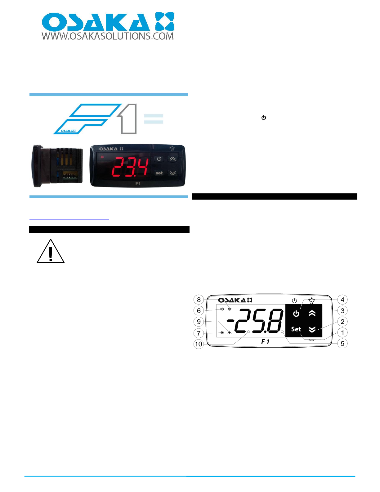
1.2 –FRONTAL PANEL DESCRIPTION
Panel frontal F 1
1 - “SET” KEY: By pressing and releasing quickly you can change
the Set Point.
By pressing for 5 seconds you can access the parameters
programming function. This function is used to edit the parameters
and to confirm the desired value.
It can be used alongside the “UP” key to modify the programming
level of the parameters.
Having the keyboard locked, if you press “SET” + “UP” during 5
seconds the keyboard will be unlocked automatically.
2 –“DOWN” Key:
You can lower the value of the SET POINT by pressing it directly
without having entered the menu. In the parameters menu you can
search the desired parameter and after pressing the selection of
the parameter with “SET” you lower or select the new value of the
parameter.

OSAKA –F 1–User’s Manual –v1 –PAG. 2
3–“UP /DEFROST” Key: Pressing it for 5 seconds initiates / stops
a cycle of manual defrosting.
In the parameters menu it is used to find the desired parameter and
after pressing the selection of the parameter with “SET” you
increase or select the new value of the parameter.
Having the keyboard locked, if you press “SET” + “UP” during 5
seconds the keyboard will be unlocked automatically.
4 -Key: By pressing and releasing quickly, you’ll be allowed to
visualize the controller’s variables (measured temperature, etc.).
In the programming function it is used to exit the parameters and
go back to the normal functioning.
If the parameter “t.UF” is programmed it allows you, pressing
during 1 second (in the normal functioning mode), to turn-on / turn-
off (Stand-by).
5 - Led SET: In the normal functioning mode it turns on when any
key is pressed, as an indication that it has been pressed.
In the programming mode it is used to indicate the programming
level of the parameters.
6 - Led OUT COOL: It indicates the state of the regulation output
(compressor or device of temperature control, solenoid, actuator,
etc.). This output is active (lit) and off (off) and disabled signal
(flashing)
7 - Led OUT HEAT: Identical to 6, but for the heating function.
8 - Led DEF: It indicates the current state of the defrosting. If the
pilot is flashing it indicates that the defrosting is being done.
9 - Led ALARM: It indicates the state of the alarm. ON (lit) OFF
(stopped) or ongoing (flashing).
10 - Led Stand-By: It indicates that the controller i son Stand-By
mode.
2 -PROGRAMMING
2.1 –QUICK SELECTION OF THE SETPOINT
In the normal programming mode, the Set Point is changed as
follows:
By quickly pressing and releasing the SET key the display will show
“SP” (or “SPE”) alternating with the programmed value. To modify
the desired temperature the “UP” key must be pressed in order to
increase the value or “DOWN” to lower it.
However, through the parameter “t.Ed” it is possible to establish
that the Set might be changed with the quick procedure of the SET
key.
The parameter can undertake a value between oF and 4, which
means that:
oF= oF = No Set may be programmed with the quick procedure of
the SET key (thus the SET key will not do anything if it is pressed
and released)
1=Only the SP can be programmed (“Normal” Set).
2=Only the SPE can be programmed (“Economic” Set).
3=Only the SP can be programmed (if it’s active) or the SPE (if it’s
active)
4=Only the Active Set can be programmed (SP or SPE)
For example, in the case of the parameter “t.Ed” = 1, the controller
will do as follows:
By pressing the SET key and releasing, the display will show “SP”
alternating the programmed value.
To modify it, the “UP” key must be pressed to increase the value or
the “DOWN” key to lower it.
If only the “SP” (t.Ed = 1) is selected once the desired value is
programmed, by pressing the SET key it remains programmed and
it exits the quick Set Point change mode.
If the Economic Set Point (“t.Ed”=3) is programmed, by pressing
and releasing the SET key the display will show “SPE” alternating
the programmed value.
To modify it the “UP” and “DOWN key must be pressed as well as
“SP” to change the Set Point.
Once the desired value is programmed, by pressing the SET key it
remains programmed and it exits the quick Set Point change mode.
To exit the Set quick programming, the SET key must always be
pressed. Otherwise, if no key is pressed for 10 seconds it will
automatically go back to the normal operating mode.
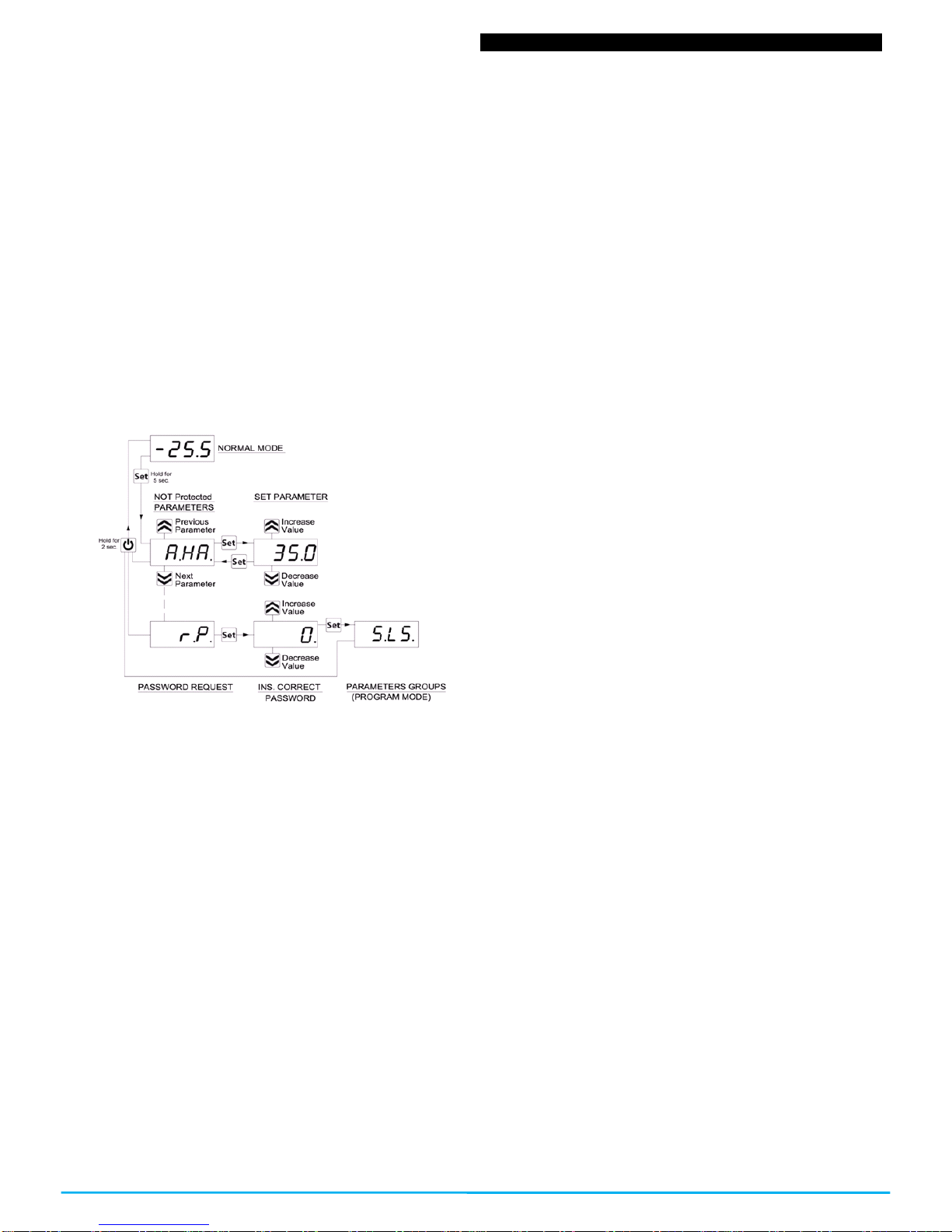
2.2 –STANDARD PROGRAMMING OF THE PARAMETERS
If the password to access the parameters is not activated (default
programming), press “SET” for 5 seconds, the display then will
show the code that identifies the first parameter and with the “UP
and “DOWN” key it will be possible to select the desired parameter.
Once the desired parameter is selected, press the “SET” key and
the programmed value in the parameter will show. This
programming will be able to be changed by pressing “UP” or
“DOWN” until you reach the desired value. Press “SET” to confirm
and memorize the value.
By once again going back to the “UP” or “DOWN” keys, it will be
possible to select another parameter and modify it successively.
To exit the programming mode: do not touch any key for 10
seconds or press the key for 5 seconds
2.3 - PARAMETERS PROTECTION THROUGH PASSWORD
The controller has a parameters protection function through a
password code which is configurable in the “t.PP” parameter.
In some instances this password is very useful so that there are no
erratic manipulations in the controller, if it is desired to activate the
password, you only need to put the desired number as the
password in the “t.PP” parameter, validate it with the SET key and
exit the programming.
When the password is programmed, press “Set” for 5 seconds to
enter the parameters menu, the controller will show the letters:
“r.P” and by pressing “Set” it will show “0”, then we must select
with the “UP” and “DOWN” keys the value of the correct password
and press “SET” to have access to the programming parameters.
If the password is correct the display will show the code of the first
parameter. The password protection can be deactivated with the
parameter “t.PP” = oF
Note: If the password were to be lost, in order to access the
parameters use the following procedure:
Turn off the electrical current of the controller and supply it again
while pressing the “SET” key until the first parameter appears. You
will the have access to the parameters and will be able to modify
the “t.PP” parameter.
OSAKA –F 1–User’s Manual –v1 –PAG. 3
4-CUSTOMIZING PARAMETERS WITH / WITHOUT PASSWORD
The controller allows you to protect only some parameters with
password and the other ones without it, so that the user has access
to the parameters that he might need, without letting you access
the entirety of parameters that belong to the technician or
manufacturer.
Method to select the programming level of the parameters:
Access the programming through the password and select the
parameter that you want to program without password. If the SET
led is flashing it means that the parameter is programmable only
with the password, i.e. it is protected. And if the led is lit and fixed it
indicates that the parameter has direct access without a password.
To modify the parameter’s visibility level keep the SET key pressed
for 5 seconds, and when the parameter starts flashing, press the
UP key without releasing the SET key, and you will be able to see
that the led’s state has changed.
The SET led will change its state indicating the new access level to
the parameter (protected, flashing led) and (direct access without
password, fixed led)
When entering the parameter’s menu we will first see the user’s
level (not protected) parameters) and then the protected ones by
introducing the password when the controller shows “r.P”
2.5 –RESTORATION OF INITIAL PARAMETERS
The controller has a mode where you can reset all the parameters
to the parameters by default from the manufacturer.
To go back to the manufacturer’s values or the parameter’s values
by default you only have to activate the protection through
password and once that is activated and when the display shows
“r.P”, enter the password -48.
Once the password is confirmed with the SET key, the display will
show for 2 seconds “---”. When the controller resets the
parameters, it makes a little testing and puts all the parameters
back at their default value.
2.6 –KEYBOARD LOCKING FUNCTION
It is possible to completely block all the keys. This function is useful
when the public has access to the control and you want to prevent
any handling. The keyboard locking function is activated by
programming the “t.Lo” parameter to a different OF value. The
programmed value in the “t.Lo”parameter is the amount of time
that the thermostat allows access to the keyboard, thus, after
surpassing this amount of time the thermostat will remain blocked.
By pressing any of the thermostat’s keys it will show “Ln” to inform
that the locking is protected (blocked).
To unlock the keyboard press “SET+UP” for 5 seconds and the
display will show “LF” and all the keyboards functions will be
operational again.
3- USAGE AND INSTALLATION WARNINGS
3.1 –USAGE WARNING
The units are manufactured as measurement and regulation
devices in compliance with EN60730-1 for a functioning of up to
2000m of altitude.
The use of these controllers in applications that are not specifically
subject to the aforementioned law must foresee all necessary
measuring and protecting adaptations.
The controllers must be adequately protected and out of reach from
liquids, dust, grease and dirtiness. They must only be accessible
with the use of a tool or safe system (except the front).
The controllers can NOT be used in environments with a dangerous
atmosphere (inflammable or explosive) without adequate
protection.
Be reminded that the installer must ensure that the norm for
electromagnetic compatibility is respected after the implantation in
the equipment’s installation, eventually using the right filters if it is
needed.
In case of failure or malfunction of the control and measuring
controllers that can create dangerous situations or damage to
people, things, animals or products (defrost food or change in its
ideal state), it is recalled that the facility should be equipped with
electronic devices or electromechanical safety and warning system.
Protective devices should be placed outside the control and
measuring controllers, responding to specific safety requirements
that are covered by the norm of the product or that common sense
might suggest.
For your own safety, it is highly recommended fulfilling the
instructions provided above.
3.2 –MECHANICAL ASSEMBLING
The 78x35mm thermostat’s housing is designed to be wall-
mounted.
Make a hole of 71x29mm and insert the controller fixing it with the
clamps that are included.
It is recommended to place the protection seal to obtain more
protection and tightness.
Avoid placing the thermostat in places exposed to high humidity or
dust, this can cause condensation or insertion of conductive
particles or substances. Ensure that you have an adequate
ventilation and avoid installing in indoor sealed boxes or areas
where the temperature exceeds the technical specifications of the
controller. Avoid installing the cables and power supply together
with the probe and install it away from devices that can generate
disturbances (electrical noise) such as motors, fans, inverters,
automatic gates, contactors, relays, solenoids, etc...
3.3 –ELECTRICAL CONNECTION
The thermostat is designed for the permanent connection between
devices; no switch is equipped with internal devices of potency for
over currents or overvoltage. Thus it is recommended to install a
general / magnet thermal (circuit breaker) switch as close as
possible to the controller and of easy access as a safety measure.
Be reminded that you must use the appropriate wire to the isolation
of voltage, current, temperature and electrical normative of the
venue. In addition you have to separate the probe signaling wires
from the supply and power wires as much as possible so that you
can avoid possible electrical noises, electromagnetic inductions,
which in some cases could be diminish or voided with RC filters,
ferritic, supply, resistors, etc. ... the use of wires with anti-parasitic
mesh and this mesh is recommended to connect on one side to
take ground
It is recommended to check that the equipment settings are
appropriate to the application before connecting wires actuators,
loads on the output relays in order to prevent malfunctions or
damage.
OSAKA –F 1–User’s Manual –v1 –PAG. 4
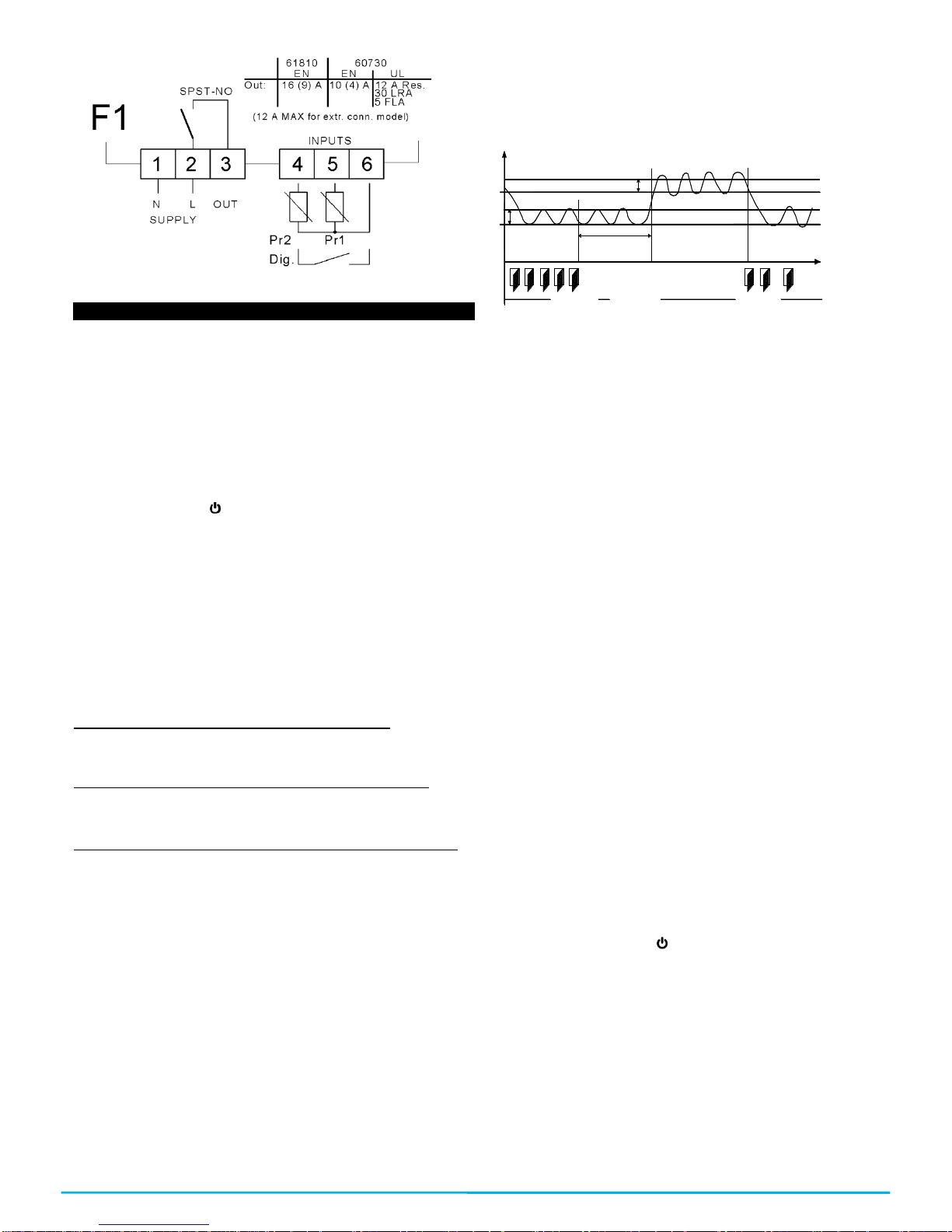
3.4 –ELECTRICAL WIRING DIAGRAM
4 - OPERATION
4.1 –ON / OFF (STAND-BY) FUNCTION
Once the thermostat is supplied it can make 2 states:
-ON: it means that the controller is running and acting over the
foreseen control function.
-STAND-BY: it means that the controller is not acting, it’s stopped.
(The display lights the Stand-by led).
To go from the STAND-BY state to the ON state it corresponds
exactly to when the controller is connected to the power. If there
was a power failure, when the power comes back the system will
always be as it was right before the interruption.
The ON/STAN-BY mode can be selected as follows:
-Through pressing the key for 3 seconds. It allows the change
from being stopped to be running.
-Through pressing the DOWN key for 3 seconds. If the parameter
“t.Fb”=4.
4.2 –“NORMAL” AND “ECONOMIC” MODE OF OPERATION.
The controller allows you to program two Set Points of regulation,
one Normal –“SP” and another one Economic –“SPE”.
Associated to each one of these Set Points, they have a specific
(hysteresis) differential, normal –“r.d”, Economic – “r.Ed”.
The commutation between the various modalities can be automatic
or manual.
OPERATION OF THE “NORMAL-ECONOMIC”MODE
It can be used in those cases in which it is necessary by
commuting to two different operation temperatures (e.g. day/night
or work days/holidays).
The NORMAL / ECONOMIC mode can be selected manually
-Through the ON/OFF key if the parameter “t.UF” =2.
-Through the DOWN/AUX key is the parameter “t.Fb” =2
-Through the digital input if the parameter “i.Fi” =6
The NORMAL / ECONOMIC mode can be selected automatically.
-After the delay time “i.Et” close the door (commutation from
Normal to economic).
-When the door opens, if the SPE Set Point is active through the
parameter “i.Et” (commutation from Normal to economic).
-When the door closes the SPE Set Point is activated after “i.Et”
parameter’s time has passed. Having the “i.tt” time passed keep
the door closed, it will change its mode (commutation from Normal
to economic).
For this function you must use the digital input configured as “i.Fi”
=1, 2 or 3.
If “i.Et” = oF the selection of the Eco/Norm mode through digital
input as a door will be deactivated.
If “i.tt” = oF, the change from Eco mode to Normal mode according
to the time a door is closed will be deactivated.
The change to the economic mode will be signaled with the
message “Eco”.
If “i.dS” = Ec the controller in economic mode will always show
“Eco”, otherwise it will show the message “Eco every 10 seconds.
Always alternating the normal visualization mode programmed in
the parameter “i.dS”.
It will be possible to program the normal SP Set Point with a value
in between the value programmed in the parameter “S.LS” and the
value programmed in the parameter “S.HS” as long as the “SPE”
Set Point (being an Economic Set Point) will be possible to
program it with a value in between the value programmed in the
parameter “SP” and the value programmed in the parameter
“S.HS”.
r.E d
SPE
SP r.d
P r1
Te m p.
"E C O "
i. E t
"N o rm ." tim e
D O O R
"N o rm ."
D A Y (s ho p op e n) N IG H T (s ho p clo se ) D A Y (s ho p op e n)
Note: In the following examples the Set Point is generally
indicated as “SP” and the differential as “r.d”, however the
controller will usually go according to the Set point and the
differential selected as active.
4.3 –INPUTS AND DISPLAY CONFIGURATION
Through the “i.uO” parameter you might choose whether you want
to measure the temperature in Celsius (Standard) or Fahrenheit
(USA) [C0=ºC / 1º (no decimal); C1=ºC / 0.1º (with decimal); F0= ºF
/ 1º; F1= ºF / 0.1º],
The controller allows you to calibrate probes that can be used to
recalibrate, according to the needs of the application, through the
parameter “i.C1” (Pr1 input), “i.C2” (Pr2 input).
The “i.P2” parameter allows you to select the use that you want to
give to the Pr2 input, in the following way:
= EP –Evaporator Probe
= Au –Auxiliary Probe (Au)
=dG –Digital input (dG)
If the Pr2 input is not being used, program it as “i.P2” = oF. If the
Pr2 probe is not configured as EP, the functions referring to the
evaporator probe will not be able to be used.
Through the “i.Ft” parameter it is possible to put a relative software
filter to the measurement of the input’s value, so that we can
diminish the sensitivity and quick temperature variation (by
increasing the time).
Through the “i.dS” parameter it is possible to establish the normal
visualization of the display which can be the measurement of the
Pr1 probe (P1), the measurement of the Pr2 probe (P2), the active
regulation Set Point (SP), the measurement of the Pr1 probe if the
controller is in the normal mode with the message “Eco”, if the
controller is in Economic (Ec) mode, or even if it is wanted for the
numeric display to be turned off (oF).
If it appears one of the measurements (“i.dS” = P1, P2, Ec) the
parameter “i.CU” allows you to put an offset that is applied to show
only the variable (all the controls of regulation will always be
done according to the correct measurement of the calibration
parameter.)
Regardless of the value imposed in the “i.dS” parameter it is
possible to visualize all the measurement’s and operation’s values
by pressing and releasing the key
The display will show the code which identifies the variable (read
below) alternating it with its value.
The variable shown are as follows:
“Pr1” –Pr1 probe measurement
“Pr2” –Pr2 probe measurement
“Lt” –Memorized Pr1 minimum temperature
“Ht” - Memorized Pr1 maximum temperature
4.4 –DIGITAL INPUT CONFIGURATION
The function for the digital input will be programmed in the “i.Fi”
parameter and the possible delay will be programmed in the “i.ti”
parameter. The “i.Fi” or digital input can be programmed for:
OSAKA –F 1–User’s Manual –v1 –PAG. 5
=0–Inactive digital input (no function)
=1–Opening of the chamber through open contact: when the
input closes the controller will show in the display oP, alternating it
with the variable established in the “i.dS” parameter. With this
operation mode, the action of the digital input also activates the
time programmed in the “A.oA” parameter, and after the time is up
an alarm will go off to signal that the door is open.
Once the door is open, the controller will go back to its normal
operation if it were to be in Eco mode and if the automatic function
of the Eco mode were to be activated, through the parameter “i.Et”.
=2–Similar to “i.Fi = 1”
=3–Opening of the chamber’s door with blocking of the control
exit through open contact: similar to “i.Fi = 1” but with exit blocking
(control exit). If open door alarms are generated (after the time has
passed “A.oA”) the exit will be deactivated.
=4- Signaling of external alarm with open contact: when the digital
contact closes and the programmed time in “i.ti” has passed, an
alarm will be activated and in the display it will show AL alternating
it with the variable established in the “i.dS” parameter.
=5–Signaling of external alarm with the deactivation of the control
exit through open contact: When the input closes (and the “i.ti”
time has passed) the exit control will be deactivated, the alarm will
be activated and the controller will show AL alternating it with the
variable established in the “i.dS” parameter.
=6–Normal / Economic mode selection with open contact: When
the input is closed you will be selecting the Economic mode. When
the input is opened, you will be selecting the Normal mode
=7–Turn ON / OFF (Stand-by) the controller through open
contact: once the input is closed (and after the “i.ti” time has
passed) the controller will turn on. On the other hand, when the
contact opens it switches to Stand-by mode.
=7–DO NOT USE.
= -1, -2, -3, etc.. –Identical functions to the previous points but with
an inverse functionality logic. It activates when the digital input’s
contact opens.
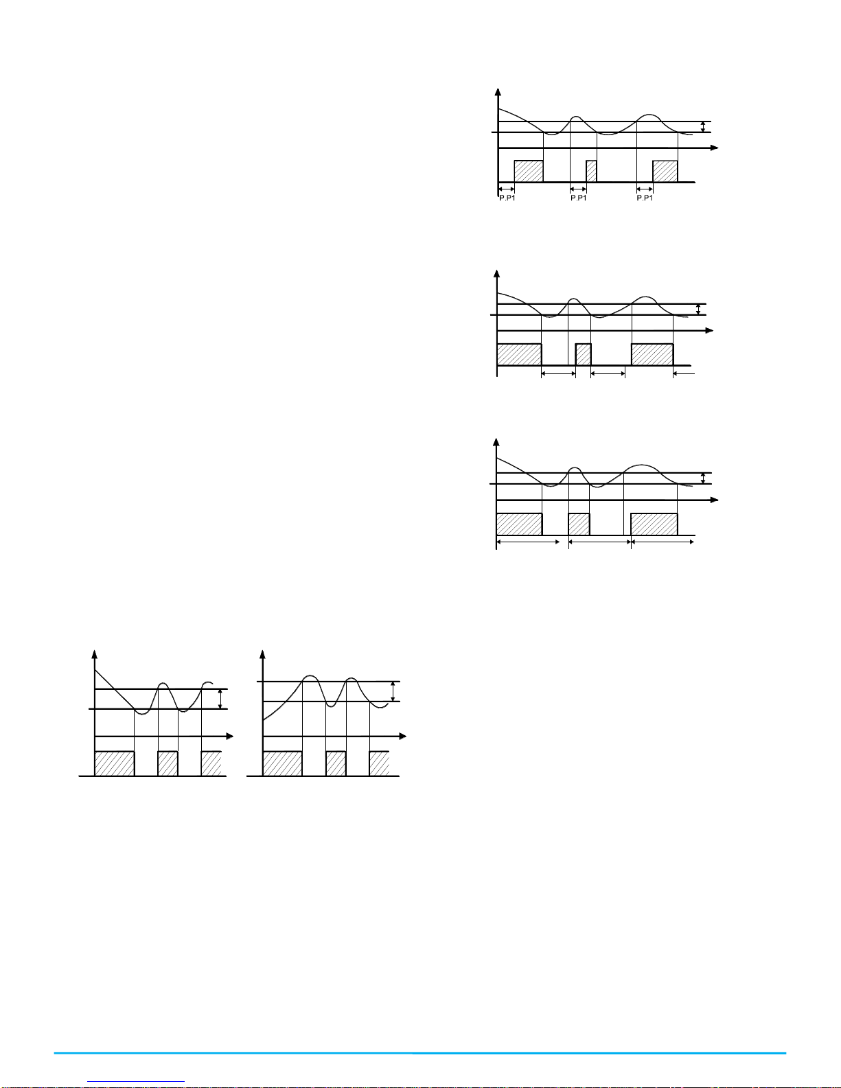
4.5 –TEMPERATURE REGULATION
The regulation mode of the controllers is an ON/OFF type over the
control output according to the measurement of the Pr1 probe, to
the active Set Point “SP” (or “SPE”), to the regulator differential
“r.d” (or “r.Ed”) and to the operation mode “r.HC”.
Referring to the operation mode programmed in the “r.HC”
parameter, the controller automatically considers the differential
with a positive value for a refrigeration control (“r.HC” =C) or with a
negative value for a heating control (“r.HC”=H).
SP
off
ON
r.H C = H
tim e
r.d
SP
Tem p.
r.d
tim e
r.H C = C
ON ONON ON ON
offoff off
Tem p.
O ut O ut
If there was a probe error it is possible for the control output to work
cyclically according to the time programmed in the “r.t1” and
(activation time) and “r.t2” (deactivation time) parameter during the
error.
By programming “r.t1” = oF the output which has a probe error will
always remain turned off.
By programming “r.t1” to any value and “r.t2” = oF the output which
has a probe error will remain turned on.
It is reminded that the operation of the temperature regulator can
be affected by the following functions:
“Compressor protection”, “Starting delay” and “Defrosting”
4.6 –COMPRESSOR PROTECTION AND STARTING DELAY
The compressor protection function helps you to avoid pretty
frequent starts of the compressor or it can also be useful to make a
time control for the relay output destined to an actuator or load.
Such function expects to activate up to 3 types of timing that you
can choose according to the appropriate system regulation.
The protection consists in avoiding various starts during the
protection time.
The first Time foresees a delay in the activation of the output
according to the time programmed in the “P.P1” parameter (starting
delay).
The second Time expects a delay in the control relay, so that it
assures a minimum time in between the stoppage and the start of
the relay’s parameter: “P.P2” (delay after stoppage or minimum
stoppage time).
The third Time expects to not allow it to start if it hasn’t exceeded
the programmed time between consecutive starts. “P.P3”
parameter (delay after consecutive starts).
If the protection is acting, preventing the start of the relay by the
programmed time, the output relay’s Led (Cold or hot) will be
flashing.
It is also possible to activate a starting delay of the regulation when
the power supply reaches the thermostat. “P.od” parameter is very
appropriate when there are various thermostats so that it doesn’t
start at the same time as the loads and so that it allows the power
line to have a smoother start.
During this delaying phase we will see od alternating with the
normal programmed visualization.
The “od” delay function is deactivated by programming it as = oF.
4.7 –AUTOMATIC DEFROSTING CONTROL
The defrosting can be activated automatically with different options:
-Defrosting by time intervals.
-Defrosting by the temperature of the evaporator.
-Defrosting by continual time of the compressor’s
operation.
In order to avoid unnecessary defrosting when the temperature of
the evaporator is high, the “d.tS” parameter establishes the
temperature given by the evaporator probe Pr2 (EP) below the
temperature of which the defrosting is enabled.
Thus, if the temperature measured in the Pr2 probe (as EP) is
higher than the one programmed in “d.tS” the defrosting will not be
enabled.
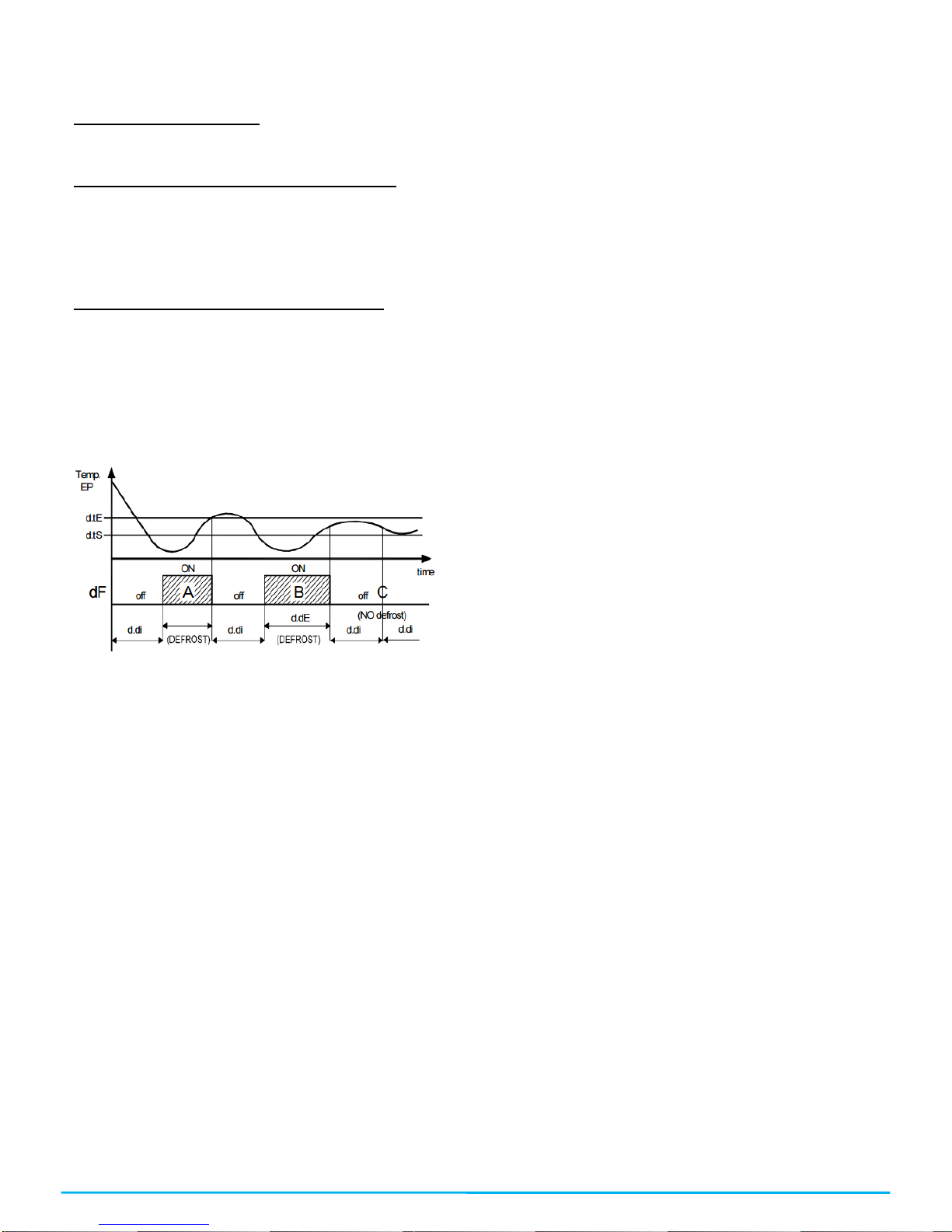
4.7.1 –DEFROSTING BY TIME INTERVALS
With the “d.di” parameter the time in between the defrosting is
configured (the interval of time between finishing one defrosting
and the beginning of another one).
It is possible to configure the first defrosting at the start of the
controller with a different time interval in the “d.Sd” parameter. If
you want to make a defrosting in each start of the controller,
program the parameter as “d.Sd” = oF. If otherwise you do not want
to make defrosting at the start of the controller, configure “d.Sd” =
“d.di”
ON
O ut off
P .P 2 P .P 2 P .P 2
SP
Tem p.
tim e
r.d
ON ON
off off
Tem p.
O ut off
ON
SP
tim e
r.d
off off off
ON ON
P .P 3
O ut o ff
SP
ON
Tem p.
P .P 3 P .P 3
tim e
r.d
off off
ON ON
OSAKA –F 1–User’s Manual –v1 –PAG. 6
If the parameter “d.di” = oF is programmed, the time intervals are
disabled and there will only be defrosting when the evaporator
probe orders it.
In the “d.PE” parameter you can choose the way in which you will
finish the defrosting, wither by time or by temperature.
“d.PE” = oF finishing by time.
The end of the defrosting is given by the configured time in the
“d.dE” parameter.
If the parameter “d.dE” = oF, the defrosting will be disabled.
“d.PE” = EP finishing by evaporator’s temperature.
With the “d.tE” parameter the finishing of the defrosting can be
according to the evaporator’s temperature. When the temperature
is not reached in the time selected in the “d.dE” parameter, the
defrosting finishes because the time is up.
If the temperature measured in the evaporator probe exceeds the
chosen temperature in the “d.tE” parameter, the defrosting is
disabled.
“d.PE” = P1 finishing by the room’s temperature.
With the “d.tE” parameter the finishing of the defrosting can also be
done according to the room’s temperature. When the temperature
is not reached in the time selected in the “d.dE” parameter, the
defrosting finishes because the time is up.
If the temperature measured in the room’s probe exceeds the
chosen temperature in the “d.tE” parameter, the defrosting is
disabled.
By programming “d.dE” = oF the defrosting by time interval or
manual defrosting will be disabled.
Defrosting operation example: the defrosting indicated as A
finishes when it reaches the “d.tE” temperature, the defrosting B
finishes because it reaches the established time without exceeding
the “d.tE”temperature, the defrosting C doesn’t start since it is
above the “d.tS” temperature, which is the one that enables the
defrosting.
An ongoing defrosting is signaled through the DEF led.
4.7.2 –DEFROSTING BY THE TEMPERATURE OF THE
EVAPORATOR.
The controller forces a defrosting cycle when the evaporator’s
probe (Pr2 probe configured as EP) goes down the value
programmed in the “d.tF” parameter and the “d.tS” delay time has
passed in order to guarantee that the evaporator truly is at a very
low temperature and it needs a defrosting (this usually is a
symptom of a low thermal interchange regarding the normal
conditions of operation).
If a delay in the function is not desired, program “d.St” = oF, when
establishing “d.tF” = -99.9 it is as if the function was actually
disabled.
4.7.3 –DEFROSTING BY THE CONTINUAL TIME OF THE
COMPRESSOR’S OPERATION.
The controller initiates a defrosting when the compressor has been
working uninterruptedly for the programmed time in the “d.cd”
parameter.
Such a function is often used when the compressor works
uninterruptedly for long periods of time, which is often a symptom
of a low interchange of temperature which is normally cause when
the evaporator freezes.
By configuring “d.cd” = oF this function will be disabled.
4.7.4 –MANUAL DEFROSTING
To activate a manual defrosting cycle press the “UP” / “DEFROST”
key for 5 seconds and the Def led will turn on and the defrosting will
start. To interrupt a defrosting cycle while it is ongoing, press the
UP key again for 5 seconds.
4.7.5 –INTERVALS AND DURATION OF THE DEFROSTING
WITH EVAPORATOR PROBE ERROR
If there was an evaporator probe error, the defrosting will be done
with time interval “d.Ei” and with a “d.EE” duration. If there was a
probe error during the passed time for the start of a new defrosting
(“d.di”) or for the finishing of a defrosting (“d.dE”) in normal
conditions, if it were lower than the configured values in the relative
parameters under broken probe conditions (“d.Ei” equals “d.di” in
an error state and “d.EE” equals “d.dE” in an error state) the start
or finish of a defrosting with the lower time value.
These functions are available when the evaporator’s probe is used,
the length of time of the defrosting is usually higher as a safety
measure ( the evaporator probe allows you to finish the defrosting
earlier if the conditions are appropriate).
4.7.6 –LOCKING OF THE DISPLAY DURING THE DEFROSTING
Through the “d.dL” and the “A.dA” you can establish the behavior
of the display during the defrosting.
The “d.dL” parameter blocks the last temperature before the
defrosting over the display (“d.dL”=on) until the finishing of the
defrosting and the temperature doesn’t go under the value of the
last memorized temperature or the condition [“SP” + “r.d”] or
exceeds the locking safety time “A.dA”. It also allows you to see
the letters which indicate the defrosting “dEF” (“dL”=Lb) and after
the defrosting is over the letters “PdF” which indicate that the
defrosting time is over but the cold temperature has not been
recovered to the regulation value [“SP” + “r.d”] or exceeds the
locking safety time “A.dA”.
Another possibility is to indicate the real temperature of the room or
cold furniture during the defrosting (“d.dL” = oF)
4.8 –ALARM FUNCTIONS
The alarm conditions of the regulator are as follows:
-Probe error: “E1”, “-E1”
-Temperature Alarm: “Hi”, “Lo”
-External Alarm: “AL”
-Open door alarm: “oP”
Any alarm condition is indicated with the ALARM led whereas the
pre-alarm condition (i.e. alarm with delay) is indicated with a
flashing led.
4.8.1 –TEMPERATURE ALARMS
The temperature alarm function works according to the reading of
the Pr1 probe, and to which type of alarm was programmed, and to
the “A.Ay” parameter, and to the “A.HA” parameter (max. alarm)
and to “A.LA” (min. alarm) and to the “A.Ad” differential (for relative
as well as absolute alarm)
Through the “A.Ay” parameter it is possible to establish whether the
“A.HA” and “A.LA” alarm sets must be considered absolute or
relative in regards to the active Set Point, if the sets must be shown
in the display as “Hi” (max. alarm) or “Lo” (min. alarm) when alarms
enter or not.
According to the selected value in the “A.Ay” parameter you can
obtain the following functions:
=1: Absolute relating to Pr1 with visualization. Display (Hi –Lo)
=2: Relative relating to Pr1 with visualization. Display (Hi –Lo)
=3: DO NOT USE
=4: DO NOT USE
=5: Absolute relating to Pr1 without visualization.
=6: Relative relating to Pr1 without visualization.
=7: DO NOT USE
=8: DO NOT USE
Through some parameters it is possible to delay the activation, just
in case the situation is cancelled and the ideal conditions are
recovered without it being an alarm. Those parameters are:
“A.PA” – Delay time when receiving power supply and turning the
regulation controller on if it is in an alarm situation.
“A.dA”- Delay time after a defrosting.
“A.At” – Acting delay time of the temperature alarm.
OSAKA –F 1–User’s Manual –v1 –PAG. 7
The temperature alarm is enabled at the end of the exclusion and it
is activated after the “A.At” time when the temperature measured in
the probe exceeds or goes lower than the corresponding max or
min alarm sets.
The alarm sets will be the same as the ones programmed in the
“A.HA” and “A.LA” parameters if the alarms are absolute
(“A.Ay”=1,5)
A .A d
A .A d
tim e
AL off
ON
A .L A
Hi
A .H A
Te m p.
Lo
off off
ON
Or the values will be [”SP”+”A.HA”] and [”SP”+”A.LA”] if the
alarms are relative (“A.Ay”=2, 6).
tim e
A .A d
A .A d
AL off
ON
Hi
A .L A
SP
A .H A
Tem p.
Lo
off off
ON
The temperature alarms of maximum and minimum can be
deactivated if we insert the parameters “A.HA” and “A.LA” = oF.
4.8.2 –EXTERNAL ALARM OF DIGITAL INPUT
The controller can signal an external alarm through the activation of
the digital input with the function programmed as “i.Fi” = 4 or 5.
The controller signals the alarm through the activation of the
ALARM led and the visualization of the label AL alternating it with
the establish variable in the “i.dS” parameter. The mode “i.Fi” = 4
doesn’t operate with any action over the control output whereas the
mode “i.Fi” = 5 foresees the deactivation of the control output in the
intervention of the digital input.
4.8.3 –OPEN DOOR ALARM
The controller can signal an open door alarm through the activation
of the digital input with the function programmed as “i.Fi”= 1, 2 or 3.
When the digital input is deactivated, the controller signals that the
door is open in the display with the oP label alternating it with the
established variable in the “i.dS” parameter. After the delay
programmed in the “A.oA” parameter, the controller signals the
alarm through the activation of the ALARM led and with the display
of the oP label.
In the open door alarm’s intervention the disabled output will be
reactivated.
4.9 –OPERATING KEY “ ” AND “DOWN/AUX”
In addition to its normal functions, two of the controller’s keys can
be configured to do other functions. The key can be defined
with the “t.UF” parameter whereas the function of the “DOWN/AUX”
key is defined with the “t.Fb” parameter.
Both parameters have the possibility of being configured to do one
of the following functions:
= oF –The key doesn’t have any specific function.
= 1 –DO NOT USE
= 2 –By pressing the key for a few seconds, it is possible to select
the rotation of the Normal or Economic (SP/SPE) active operation
modality. When the key is pressed, the display will show (flashing)
for one second the code of the active set point (“SP” or “SPE”).
= 3 –By pressing the key for some seconds it’s possible to change
the controller from an ON state to Stand-by and vice-versa
=4–DO NOT USE
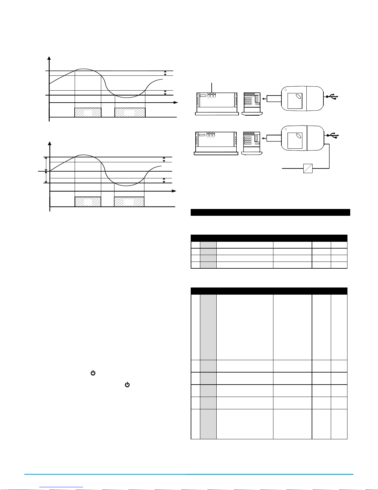
4.10 –PARAMETERS CONFIGURATION WITH KEY USB
The controller has a connector that allows you to transfer the
operation parameters to the KEY USB device, which is equipped
with a connector of 5 poles. The KEY USB device is used to
program the controllers that must have the same configuration of
parameters, or to save a copy of the controller’s programming and
be able to transfer it quickly. The KEY USB has a USB connection
input, which allows connecting it to a PC, with which through the
Universal Conf or Osaka Set Up configuration software it is
possible to configure the operation parameters.
S U P P L Y
U S B
S U P P L Y A D A P T E R
A C S U P P L Y 1 2 V D C
U S B
For more information, please consult the manual of the KEY USB.
5 –PARAMETERS LISTING
“S” Relative parameters to the Set Point
Par.
Description
Range
Def.
Note
1
S.LS
Minimum Set Point
-99.9 ÷ HS
-50.0
2
S.HS
Maximum Set Point
LS ÷ 999
99.9
3
SP
Set Point
LS ÷ HS
0.0
4
SPE
Economic Set Point
SP ÷ S.HS
“i” Relative parameters to probes and digital inputs
Par.
Description
Range
Def.
Note
5
i.uP
Measurement and
resolution unit (decimal
point).
C0= °C With resolution
1°
F0= °F With resolution
1°
C1 =°C With resolution
0,1°
F1 = °F With resolution
0,1°
C0 / F0 / C1 /
F1
C1
6
i.Ft
Measuring filter.
oF ÷ 20.0
sec
2.0
7
i.C1
Calibration probe Pr1
(room).
-30 ÷ 30
°C/°F
0.0
8
i.C2
Calibration probe Pr2.
-30 ÷ 30
°C/°F
0.0
9
i.CU
Visualization offset
-30.0 ÷ 30.0
°C/°F
0.0
10
i.P2
Pr2 input usage:
oF = No function
EP = Evaporator
Au = Auxiliary probe
dG = digital input
oF –EP –Au –
dG
dG
KEY USB
OSAKA –F 1–User’s Manual –v1 –PAG. 8
11
i.Fi
Function and logic of
the digital input:
0 = No function
1,2 = Door opening
3 = Door opening with
door blocking
4 = External alarm
5 = External alarm with
exit’s deactivation.
6 = Selection in
between Normal or
Economic mode.
7 = Start / Stop (Stand-
by)
8 = DO NOT USE
-8 / -7 / -6 / -5 /
-4 / -3 / -2 / -1 /
0 / 1 / 2 / 3 / 4 /
5 / 6 / 7 / 8
0
12
i.ti
Digital input delay.
oF ÷ 0.01 ÷
9.59 (min.sec)
÷ 99.5
(min.sec)
oF
13
i.Et
Delay time of
economic mode
activation when the
door is closed
oF = disabled function.
oF/ 0.01 ÷ 9.59
(hrs.min.) ÷
99.5
(hrs.min.x10)
oF
14
i.tt
Maximum time of
operation in economic
mode.
oF = disabled function
oF/ 0.01 ÷ 9.59
(hrs.min. ) ÷
99.5
(hrs.min.x10)
oF
15
i.dS
Variable often shown
in the display:
P1 = Measuring probe
Pr1.
P2 = Measuring probe
Pr2
Ec = Pr1 Measure in
normal mode and Eco
message in Eco mode
SP= Active Set Point
oF = Turned off display
P1 / P2 / P3 /
Ec / SP / oF
P1
“r” Temperature regulation parameters
Par.
Description
Range
Def.
Note
16
r.d
Regulation differential
(hysteresis)
0 ÷ 30
°C/°F
2.0
17
r.Ed
Regulation differential
(hysteresis) in Eco
mode
0.0 ÷ 30.0
°C/°F
2.0
18
r.t1
Output activation time
in case the Pr1 probe
breaks.
oF ÷ 0.01 ÷
9.59 (min.sec)
÷ 99.5
(min.sec)
oF
19
r.t2
Output stopping time
because of the
breaking of the probe.
oF ÷ 0.01 ÷
9.59 (min.sec)
÷ 99.5
(min.sec)
oF
20
r.HC
Regulation mode:
H = Heat
C = Cool
Nr, HC, C3 = DO NOT
USE
H / C / nr / HC /
C3
C
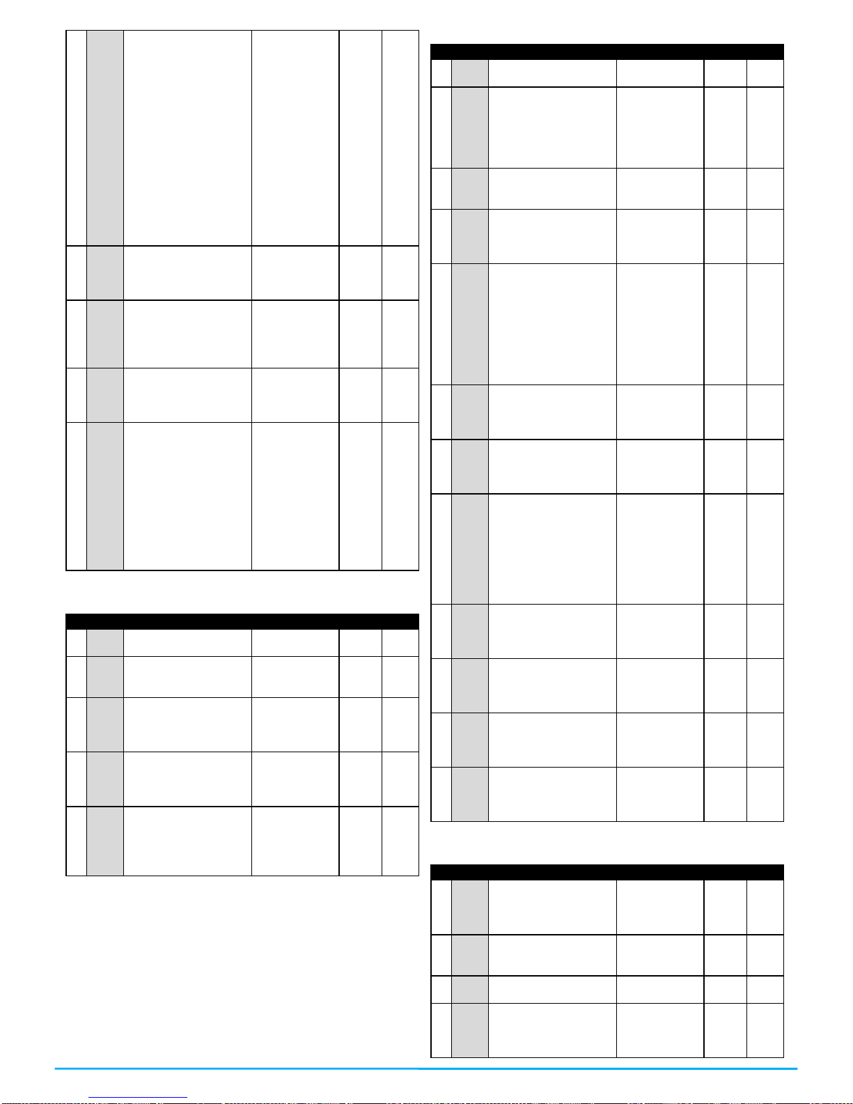
“d” Relative parameters to the defrosting
Par.
Description
Range
Def.
Note
21
d.tE
Defrosting finishing
temperature
- 99.9 ÷ 999
°C/°F
10.0
22
d.tS
Temperature from
which the beginning of
the defrosting is
allowed. If Pr2 is
higher tan d.tS it won’t
start the defrosting.
- 99.9 ÷ 999
°C/°F
2.0
23
d.tF
Temperature that
forces the beginning of
the defrosting.
- 99.9 ÷ 999
°C/°F
-99.9
24
d.St
Delay in the beginning
of a defrosting
because of Pr2
evaporator probe
oF/ 0.01 ÷ 9.59
(min.sec) ÷
99.5
(min.sec.x10)
1.00
25
d.dL
Display locking in the
defrosting:
oF = not active
on = active with last
measurement.
Lb = active with
message (“dEF” in
defrosting and “PdF” in
post-defrosting)
oF - on –Lb
oF
26
d.cd
Defrosting starts due
to continual operation
of the compressor
oF/ 0.01 ÷ 9.59
(hrs.min. ) ÷
99.5
(hrs.min.x10)
oF
27
d.dE
Maximum duration of
the defrosting.
oF ÷ 0.01 ÷
9.59 (min.sec)
÷ 99.5
(min.sec)
oF
28
d.PE
Probe selection of the
finish of the defrosting:
- oF = finishes by time
alone.
- EP = by Pr2 probe
temperature = EP.
- P1 = by Pr1 probe
temperature = room.
oF –EP –P1
EP
29
d.di
Defrosting intervals
oF ÷ 0.01 ÷
9.59 (hrs.min)
÷ 99.5
(hrs.min)
oF
30
d.Sd
Defrosting delay when
starting. (oF = it allows
defrosting when it
starts)
oF ÷ 0.01 ÷
9.59 (hrs.min)
÷ 99.5
(hrs.min)
oF
31
d.Ei
Defrosting intervals if
there is a probe error.
oF ÷ 0.01 ÷
9.59 (hrs.min)
÷ 99.5
(hrs.min)
6.00
32
d.EE
Duration of the
defrosting if there is a
probe error
oF ÷ 0.01 ÷
9.59 (min.sec)
÷ 99.5
(min.sec)
10.0
“P” Compressor Protection parameters
Par.
Description
Range
Def.
Note
33
P.P1
Output delay when
starting
oF÷ 0.01 ÷
9.59 (min.sec )
÷ 99.5
(min.sec.x10)
oF
34
P.P2
Delay after stopping or
minimum time of
stoppage.
oF ÷ 0.01 ÷
99.5
oF
35
P.P3
Minimum time after two
output connections.
oF ÷ 0.01 ÷
99.5
oF
36
P.od
Delay of the
compressor’s start
when it gives voltage
to the controller.
oF ÷ 0.01 ÷
9.59 (min.sec)
÷ 99.5
(min.sec)
oF

OSAKA –F 1–User’s Manual –v1 –PAG. 9
“A” Alarm configuration parameters
Par.
Description
Range
Def.
Note
37
A.Ay
Temperature alarm
type:
1 = Absolute for Pr1
probe with visualization
in the display (Hi-Lo).
2 = Relative for Pr1
probe with visualization
in the display (Hi-Lo).
3, 4 = DO NOT USE
5 = Absolute for Pr1
probe without display’s
visualization.
6 = Relative for Pr1
probe without display’s
visualization.
7, 8 = DO NOT USE
1 / 2 / 3 / 4 / 5 /
6 / 7 / 8
1
38
A.HA
Alarm set for high
temperatures.
oF / - 99.9 ÷
999 °C/°F
OFF
39
A.LA
Alarm set for low
temperatures.
oF / - 99.9 ÷
999 °C/°F
OFF
40
A.Ad
Temperature alarm
differential.
0 ÷ 30
°C/°F
1.0
41
A.At
Temperature alarm
delay.
oF ÷ 0.01 ÷
9.59 (min.sec)
÷ 99.5
(min.sec)
oF
42
A.PA
Alarms connection
delay when turning on.
oF ÷ 0.01 ÷
9.59 (hrs.min)
÷ 99.5
(hrs.min)
2.00
43
A.dA
Temperature alarm
delay after the
defrosting and locking
of the display during
the defrosting.
oF ÷ 0.01 ÷
9.59 (hrs.min)
÷ 99.5
(hrs.min)
1.00
44
A.oA
Open door alarm
delay.
oF ÷ 0.01 ÷
9.59 (min.sec)
÷ 99.5
(min.sec)
3.00
“t” – Keyboard configuration parameters.
Par.
Description
Range
Def.
Note
45
t.UF
“F” key operation
mode.
oF = no function
1= DO NOT USE
2= Select economic
mode.
3= Start / Stop
(Stand-by)
4 = DO NOT USE
oF / 1 / 2 / 3 / 4
oF
46
t.Fb
Down/Aux key
operation mode (see
“t.UF”)
oF / 1 / 2 / 3 / 4
oF
47
t.Lo
Automatic keyboard
locking.
oF ÷ 0.01 ÷
9.59 (min.sec)
÷ 30.0
(min.sec)
oF
48
t.Ed
Set Point visibility with
quick procedure with
SET key
oF = none
1 = SP
2 = SPE
3 = SP and SPE
4 = Active SP
5, 6 = DO NOT USE
oF / 1 / 2 / 3 / 5
/6
1
49
t.PP
Password to access
the operational
parameters.
oF ÷ 999
oF
6 –ERROS, MAINTENANCE AND WARRANTY
6.1 –SIGNALING
Error
Reason
Action
E1 -E1
The relative probe can
be broken (E) or in
short-circuit (-E), or have
a value that is out of the
programmed range.
Verify the connection of
the probe to the
controller and verify the
correct operation of the
probe (it is useful to
have the ohm values of
the probes)
EPr
Possible anomaly in the
EEPROM memory.
Press the SET key. Turn
off and turn on the
controller.
Err
Fatal Error of the
controller’s memory.
Replace the controller or
send it for a possible
reparation.
Display indication
Reason
od
Delay at the start after power supplying the
controller.
Ln
Locked keyboard.
Hi
High temperature alarm
Lo
Low temperature alarm.
AL
Ongoing digital input alarm.
oP
Open door
dEF
Active defrosting, it shows if “d.dL” =Lb
PdF
Defrosting finished, recovering cold if
“d.dL” = Lb
Eco
Economic mode selected.

OSAKA –F 1–User’s Manual –v1 –PAG. 10
6.2 –CLEANING
It is recommended to clean the controller with a wet cloth alone. Do
not use soap nor any other neutral detergent.
6.3 –WARRANTY AND REPAIRING
The controller has a warranty that takes form either in reparation or
in replacement, if the error is due to a manufacturing defect in
materials which are up to 12 months old from the purchasing date.
OSAKA SOLUTIONS will automatically make void this warranty and
will not be held accountable for possible damage that may result
from:
-The use, installation or handling which is inappropriate or
different than the one written here, and specially when is
differs from the safety requirements established by the
regulation.
-The usage in applications, machines or electrical panels
that do not provide adequate protection against liquids,
dust, grease and electric shocks in the conditions of
mounting.
-The inexperienced handling, and / or alteration of the
product.
-The installation / use in applications, machines or
electrical panels that do not comply with the valid norm.
If the product has a defect during the warranty time or outside of
aforementioned time, you should contact the after-sales service to
go through the appropriate procedure. Request a repairing
document “RMA” (by email or fax) and fill it. It is necessary to send
the RMA and the controller to the SAT OSAKA with prepaid
shipping.
7 –TECHNICAL DATA
7.1 –ELECTRICAL FEATURES
Supply: 115 or 230 VAC +/- 10%
AC Frequency: 50/60 Hz
Consumption: 2 VA
Input: 2 inputs for NTC (103AT-2, 10 K Ω@ 25 °C) temperature
probes; 1 digital input by free voltage contact as an alternative
option to the 2 probe inputs.
Output - 16A -
1HP 250V,
1/2HP 125 VAC
16 (9) A
10 (4) A
12 A Res., 30
LRA,
5 FLA
Electrical life relay output: 100000 op. in compliance with EN 60730
Supply: Type 1.B in compliance EN 60730-1
Overvoltage category: II
Device’s class: Class II
Isolation: Isolated by piece low voltage (power 115/230 V and relay
outputs); and part low voltage inputs; electrically isolated between
output and supply.
7.2 –MECHANICAL FEATURES
Body: Self-extinguishing UL 94 V0 plastic.
Category of resistance to heat and fire: D
Dimensions: 78 X 35 mm, depth. 34 mm or 42.2 according to the
terminal block.
Weight: 105 g approx.
Installation: on panel, recessed 71x29mm
Connection: Inputs: Cable of 0,14…4,5mm2 / AWG 28...16;
Supply and output: 0,2…2,5 mm2 / AWG 24...14
Sealing degree: IP65 (NEMA 3S) with sealing gasket
Operating room temperature: 0 T 50 ° C
Operating humidity: <95% RH non-condensing
Storage and transportation temperature: -25 ° C T 60
7.3 –MECHANICAL DIMENSIONS, HOLES, AND MOUNTING
R E C O M M E N D E D
P A N E L C U T O U T
29
m in. 15 m m
m in. 12 m m
71
PANEL
B R A C K E T S
34
M A X . 2,5 m m
7.4 –FUNCTIONAL FEATURES
Temperature regulation: ON/OFF
Defrosting control: By intervals due to the stoppage of the
compressor.
Measuring range: -50…109ºC / -58…228 ºF.
Display resolution: 1º or 0,1º (range -99.9…99.9 ºC)
Total accuracy: +*- (0,5% fs + 1 digit)
Average speed time (without filter): 130 ms.
Display: 3 red digits h 15,5mm.
Software class structure: Class A
Time maintenance of the internal clock without power supply:
Around four hours.
Compliance: 2004/108/CE (EN55022: class B; EN61000-4-2: air
8KV, contact 4KV.; EN61000-4-3: 10V/m; EN61000-4-4: power
supply 2KV relay output, 1KV inputs; EN61000-4-5: common power
supply 2KV, 1 KV\ differential mode; EN61000-4-6: 3V); Directive
2006/95/CE (EN 60730-1, EN 60730-2-9).Regulation 37/2005/CE
(EN13485 air, S, A, 2,- 50°C +90°C if it is used with NTC probe
103AT11).

OSAKA –F 1–User’s Manual –v1 –PAG. 11
Table of contents
Other Osaka Thermostat manuals


