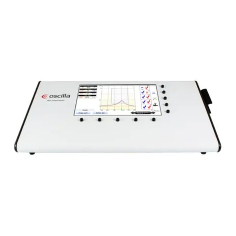
OSCILLA USB310 User manual

ID: 1530 / ver. 205
1

ID: 1530 / ver. 205
2
1. Table of content
1. TABLE OF CONTENT.........................................................................................................................................................2
2. SCHEMATICS ......................................................................................................................................................................3
3. CIRCUIT DESCRIPTION, PCB .........................................................................................................................................5
4. TOP ASSEMBLY DRAWING.............................................................................................................................................7
5. BOTTOM ASSEMBLY DRAWING ...................................................................................................................................8
6. PART LIST, PCB ..................................................................................................................................................................9
7. HW ASSEMBLY OF AUDIOMETER AND HEADSET ................................................................................................14
8. TECHNICAL SPECIFICATIONS ....................................................................................................................................22
WARNING AND SAFETY NOTICES..................................................................................................................................26
SYMBOLS................................................................................................................................................................................27
EMC..........................................................................................................................................................................................27
RESPONSIBILITY OF THE MANUFACTURER..............................................................................................................29

ID: 1530 / ver. 205
3
2. Schematics

ID: 1530 / ver. 205
4

ID: 1530 / ver. 205
5
3. Circuit description, PCB
The DA7 PCB can be used in the production of two different main product types, with or
without Audio Streaming capabilities. The type without Audio Streaming capabilities are
mounted without microphone components, without uSDcard components and with a smaller
ARM7 MCU, which is documented in the component list.
The DA7 board is built around an Atmel ARM7 MCU and two Texas Instruments 24-bit DAC’s.
The DAC’s are followed by two discrete transistor output stages and output relays. Signals are
generated by the ARM firmware. The board is capable of streaming sound through USB too, in
both directions.
Power supply
The regulated power supply is divided into 2 sections, a permanently active 3.3V LDO
regulator (LP2985), and a 5V boost/buck switching regulator (U5) which the ARM can turn on
and off.
The 3.3V regulator powers the ARM and - through a FET (T15) –the DACs’ digital section, an
eeprom, a flipflop, an optional Micro SD card and an optional microphone preamplifier. The
FET is controlled by the ARM which turns it off when the device goes into standby mode.
The 5V regulator powers the DACs’ analog section. It ensures a stable 5V output with input
voltages both below and above 5V. It is powered through a FET (T14) which is controlled by
the ARM.
Both FET’s has soft turn-on RC-networks to reduce inrush current at turn-on.
The output stages are powered by the unregulated USB power line, through T14 and filtering
RC networks (R5, C42, R20, C44).
ARM microcontroller
The ARM (U1) runs at 48MHz delivered from an internal PLL which runs on an 18.432MHz
crystal. It controls the DAC’s, USB communication, EEPROM, SD card, power supply, output
stage idle current and output relays.
DAC’s
The analog signals are generated by two 24-bit DAC’s. They are connected to the ARM
through an I2S bus. The DAC’s are stereo, but they operate in mono mode with the two
differential current outputs connected together. They share the same stereo I2S bus, one DAC
reads the left signal and the other reads the right signal. 32 bits of data is delivered to each
DAC, but only 24 bits are used. A 7474 flipflop (IC1A) is inserted in the L/R clock signal line to
divide the clock by two.

ID: 1530 / ver. 205
6
Output stages
(Left channel described)
The output stages are class AB push-pull stages with output capacitors. The output transistors
are coupled as common emitters to allow rail-to-rail output swing. The paralleled differential
current outputs from the DAC’s drive the base and emitter of the input transistor T1. This
converts the balanced signal to single-ended. Its collector drives the lower output transistor T4
directly and, through T2, the upper output transistor T3. T2 is configured as common base
seen from the signals’ point of view. T2 also controls the idle current in the output transistors.
This is done from the ARM via a filtered PWM channel that sets the base voltage. Feedback is
provided by R4, and the filter capacitors C14 and C15 reduces the DACs’ high frequency
noise.
Output relays
3 small low resistance CMOS switches are used to direct the signal to either the headphones
or the bone conductor. They handle the signals after the output capacitors, so the signals
swing below ground level. Therefore, the relays are powered by +-2.7V. The -2.7V is
generated by a charge pump (C46, C48 and D4) driven by an ARM pin. One of the relays is
used to switch the ground line of the bone conductor so it uses the same ground return as the
output channel that drives it.
Eeprom
An I2C eeprom (AT24C16) is used to keep calibration data. This is connected to the ARM
through two pins that acts as an I2C bus.
Microphone and preamp (optional)
An opamp is used to amplify the signal from the microphone. This signal is then sent to one of
the ARMs’ A/D inputs. The ARM samples it and streams it to the host computer via USB for
use with talk-back facility. Talk-forward is provided by streaming sound from the host computer
and sending it to the DAC’s.
Micro SD card reader (optional)
A micro SD card reader is connected to the ARMs’ SPI bus for accessing a card in SPI mode.
In addition the other data pins from the card are connected to the ARM, to allow operation in
SD mode. The card is used to store sound files to play back through the DAC’s for use with
speech audiometry.

ID: 1530 / ver. 205
7
4. Top Assembly Drawing

ID: 1530 / ver. 205
8
5. Bottom Assembly Drawing

ID: 1530 / ver. 205
9
6. Part list, PCB
Part
Value
Device
Package
Description
U2
7474
7474
TSSOP14
Dual D type positive edge triggered FLIP FLOP, preset and
clear
X1
ABM3
ABM3
ABM3
Crystal Case Type: 5 x 3.2mm SMD
U3
AT24C16B
AT24C16BSOIC8
SOIC08
U1
AT91SAM7S256
AT91SAM7S256LQFP64
LQFP64
D4
BAS40-04
BAS40-04
SOT23
Silicon Schottky Diodes
D1
BAV99W
BAV99W
SOT323
D2
BAV99W
BAV99W
SOT323
D5
BAV99W
BAV99W
SOT323
D6
BAV99W
BAV99W
SOT323
T2
BC847W
BC847W
SOT323
T6
BC847W
BC847W
SOT323
T9
BC847W
BC847W
SOT323
T1
BC857W
BC857W
SOT323
T5
BC857W
BC857W
SOT323
T10
BC857W
BC857W
SOT323
T11
BC857W
BC857W
SOT323
T4
BC868
BC868
SOT89
T8
BC868
BC868
SOT89
T3
BC869
BC869
SOT89
T7
BC869
BC869
SOT89
T14
BSH205
BSH205
SOT23
T15
BSH205
BSH205
SOT23
T16
BSH205
BSH205
SOT23
C1
100n
C-EUC0603
C0603
CAPACITOR, European symbol
C2
100n
C-EUC0603
C0603
CAPACITOR, European symbol
C4
100n
C-EUC0603
C0603
CAPACITOR, European symbol
C5
100n
C-EUC0603
C0603
CAPACITOR, European symbol
C6
100n
C-EUC0603
C0603
CAPACITOR, European symbol
C7
10p
C-EUC0603
C0603
CAPACITOR, European symbol
C8
10p
C-EUC0603
C0603
CAPACITOR, European symbol
C9
10n
C-EUC0603
C0603
CAPACITOR, European symbol
C10
1n
C-EUC0603
C0603
CAPACITOR, European symbol

ID: 1530 / ver. 205
10
C11
100n
C-EUC0603
C0603
CAPACITOR, European symbol
C12
100n
C-EUC0603
C0603
CAPACITOR, European symbol
C14
10n
C-EUC0603
C0603
CAPACITOR, European symbol
C15
10n
C-EUC0603
C0603
CAPACITOR, European symbol
C17
100n
C-EUC0603
C0603
CAPACITOR, European symbol
C19
100n
C-EUC0603
C0603
CAPACITOR, European symbol
C20
1n
C-EUC0603
C0603
CAPACITOR, European symbol
C22
100n
C-EUC0603
C0603
CAPACITOR, European symbol
C27
10n
C-EUC0603
C0603
CAPACITOR, European symbol
C30
100n
C-EUC0603
C0603
CAPACITOR, European symbol
C31
1u
C-EUC0603
C0603
CAPACITOR, European symbol
C35
100n
C-EUC0603
C0603
CAPACITOR, European symbol
C38
1u
C-EUC0603
C0603
CAPACITOR, European symbol
C40
10n
C-EUC0603
C0603
CAPACITOR, European symbol
C41
10n
C-EUC0603
C0603
CAPACITOR, European symbol
C46
100n
C-EUC0603
C0603
CAPACITOR, European symbol
C47
100n
C-EUC0603
C0603
CAPACITOR, European symbol
C48
100n
C-EUC0603
C0603
CAPACITOR, European symbol
C50
100n
C-EUC0603
C0603
CAPACITOR, European symbol
C51
1u
C-EUC0603
C0603
CAPACITOR, European symbol
C53
100n
C-EUC0603
C0603
CAPACITOR, European symbol
C54
100n
C-EUC0603
C0603
CAPACITOR, European symbol
C56
1n
C-EUC0603
C0603
CAPACITOR, European symbol
C57
1n
C-EUC0603
C0603
CAPACITOR, European symbol
C58
100n
C-EUC0603
C0603
CAPACITOR, European symbol
C59
100n
C-EUC0603
C0603
CAPACITOR, European symbol
C13
4.7u
C-EUC1206
C1206
CAPACITOR, European symbol
C16
2.2u
C-EUC1206
C1206
CAPACITOR, European symbol
C32
2.2u
C-EUC1206
C1206
CAPACITOR, European symbol
C3
47u
CPOL-EUSMCB
SMC_B
POLARIZED CAPACITOR, European symbol
C18
47u
CPOL-EUSMCB
SMC_B
POLARIZED CAPACITOR, European symbol
C23
47u
CPOL-EUSMCB
SMC_B
POLARIZED CAPACITOR, European symbol
C24
47u
CPOL-EUSMCB
SMC_B
POLARIZED CAPACITOR, European symbol
C25
47u
CPOL-EUSMCB
SMC_B
POLARIZED CAPACITOR, European symbol
C26
47u
CPOL-EUSMCB
SMC_B
POLARIZED CAPACITOR, European symbol
C28
47u
CPOL-EUSMCB
SMC_B
POLARIZED CAPACITOR, European symbol
C29
47u
CPOL-EUSMCB
SMC_B
POLARIZED CAPACITOR, European symbol

ID: 1530 / ver. 205
11
C34
47u
CPOL-EUSMCB
SMC_B
POLARIZED CAPACITOR, European symbol
C36
47u
CPOL-EUSMCB
SMC_B
POLARIZED CAPACITOR, European symbol
C37
47u
CPOL-EUSMCB
SMC_B
POLARIZED CAPACITOR, European symbol
C39
47u
CPOL-EUSMCB
SMC_B
POLARIZED CAPACITOR, European symbol
C45
47u
CPOL-EUSMCB
SMC_B
POLARIZED CAPACITOR, European symbol
C52
47u
CPOL-EUSMCB
SMC_B
POLARIZED CAPACITOR, European symbol
C55
47u
CPOL-EUSMCB
SMC_B
POLARIZED CAPACITOR, European symbol
C21
220u
CPOL-EUSMCC
SMC_C
POLARIZED CAPACITOR, European symbol
C42
220u
CPOL-EUSMCC
SMC_C
POLARIZED CAPACITOR, European symbol
C43
220u
CPOL-EUSMCC
SMC_C
POLARIZED CAPACITOR, European symbol
C44
220u
CPOL-EUSMCC
SMC_C
POLARIZED CAPACITOR, European symbol
D3
MMSZ6V2T1G
DIODE-DO-214AC
DO-214AC
DIODE
D7
MMSZ6V2T1G
DIODE-DO-214AC
DO-214AC
DIODE
MIC
JP1E
JP1
JUMPER
RST
JP1E
JP1
JUMPER
SPKL
JP1E
JP1
JUMPER
SPKR
JP1E
JP1
JUMPER
TST
JP1E
JP1
JUMPER
JTAG
JP4E
JP4
JUMPER
LED1
LEDCHIPLED_0805
CHIPLED_0805
LED
U11
LP2985-3V3
LP2985-3V3
SOT23-5
VOLTAGE REGULATOR
U4
MC33201
MC33201SOIC8
SOIC08
MICRO_SD
MICRO_SD
MICRO_SD
MICRO_SD
BONE
MINI_JACK3
MINI_JACK3
MINI_JACK3
U9
PCM1798
PCM1798
SSOP28
U10
PCM1798
PCM1798
SSOP28
USB
PINHD-1X5
1X05
PIN HEADER
R1
1k5
R-EU_R0603
R0603
RESISTOR, European symbol
R2
200
R-EU_R0603
R0603
RESISTOR, European symbol
R3
100
R-EU_R0603
R0603
RESISTOR, European symbol
R4
200
R-EU_R0603
R0603
RESISTOR, European symbol
R5
10
R-EU_R0603
R0603
RESISTOR, European symbol
R6
10k
R-EU_R0603
R0603
RESISTOR, European symbol
R7
100
R-EU_R0603
R0603
RESISTOR, European symbol
R8
200
R-EU_R0603
R0603
RESISTOR, European symbol
R9
200
R-EU_R0603
R0603
RESISTOR, European symbol
R10
10k
R-EU_R0603
R0603
RESISTOR, European symbol

ID: 1530 / ver. 205
12
R11
6.2k
R-EU_R0603
R0603
RESISTOR, European symbol
R12
680
R-EU_R0603
R0603
RESISTOR, European symbol
R13
680
R-EU_R0603
R0603
RESISTOR, European symbol
R14
680
R-EU_R0603
R0603
RESISTOR, European symbol
R15
680
R-EU_R0603
R0603
RESISTOR, European symbol
R16
47k
R-EU_R0603
R0603
RESISTOR, European symbol
R17
680
R-EU_R0603
R0603
RESISTOR, European symbol
R18
47k
R-EU_R0603
R0603
RESISTOR, European symbol
R19
10k
R-EU_R0603
R0603
RESISTOR, European symbol
R20
10
R-EU_R0603
R0603
RESISTOR, European symbol
R21
220k
R-EU_R0603
R0603
RESISTOR, European symbol
R22
2k7
R-EU_R0603
R0603
RESISTOR, European symbol
R23
10k
R-EU_R0603
R0603
RESISTOR, European symbol
R24
10k
R-EU_R0603
R0603
RESISTOR, European symbol
R25
4.7k
R-EU_R0603
R0603
RESISTOR, European symbol
R26
2k7
R-EU_R0603
R0603
RESISTOR, European symbol
R27
1k5
R-EU_R0603
R0603
RESISTOR, European symbol
R28
10k
R-EU_R0603
R0603
RESISTOR, European symbol
R29
22
R-EU_R0603
R0603
RESISTOR, European symbol
R30
22
R-EU_R0603
R0603
RESISTOR, European symbol
R31
330k
R-EU_R0603
R0603
RESISTOR, European symbol
R32
330k
R-EU_R0603
R0603
RESISTOR, European symbol
R33
1k
R-EU_R0603
R0603
RESISTOR, European symbol
R34
1k
R-EU_R0603
R0603
RESISTOR, European symbol
R35
1M
R-EU_R0603
R0603
RESISTOR, European symbol
R36
1M
R-EU_R0603
R0603
RESISTOR, European symbol
R37
1M
R-EU_R0603
R0603
RESISTOR, European symbol
R38
1M
R-EU_R0603
R0603
RESISTOR, European symbol
R39
47k
R-EU_R0603
R0603
RESISTOR, European symbol
R40
47k
R-EU_R0603
R0603
RESISTOR, European symbol
R41
1M
R-EU_R0603
R0603
RESISTOR, European symbol
R42
4.7k
R-EU_R0603
R0603
RESISTOR, European symbol
R43
680
R-EU_R0603
R0603
RESISTOR, European symbol
R44
10k
R-EU_R0603
R0603
RESISTOR, European symbol
R45
10k
R-EU_R0603
R0603
RESISTOR, European symbol
R46
680
R-EU_R0603
R0603
RESISTOR, European symbol
R47
1k
R-EU_R0603
R0603
RESISTOR, European symbol

ID: 1530 / ver. 205
13
R49
10
R-EU_R0603
R0603
RESISTOR, European symbol
R50
10
R-EU_R0603
R0603
RESISTOR, European symbol
F1
0.5A
SF-0603F
F0603
S1
SWITCH
TACT_SWITCH
TACT_SWITCH
U5
TPS63030
S-PDSO-N10
2,5-mm × 2,5-mm QFN-10
U6
TS5A3159A
TS5A3159A
SOT23-6
U7
TS5A3159A
TS5A3159A
SOT23-6
U8
TS5A3159A
TS5A3159A
SOT23-6
L1
4.7uH
VLF3012AT-4R7MR74
COILFP
2.8x2.6x1mm SMT Power Inductors

ID: 1530 / ver. 205
14
7. HW Assembly of Audiometer and headset
Assembly instructions for DA7 audiometers (Oscilla USB-310, 330, 350B, 350BS, 350SP).
The order of operations is free, as long as assembly takes place cf. collar specified in this
procedure.
1.
There is a Peltor headset (Item no.: 44173) and a
cable of the type "Y cable for USB" (Item no.: 44715)
2.
Y cable is stripped in one and tinned as shown.
3.
The stripped cable ends are passed through the holes
in the headset and a knot is tied on the cable approx.
6 cm from the end. A label with the cable's tracking number is attached to the head gasket.

ID: 1530 / ver. 205
15
4.
After this, plug pins (item no.: 44169) are soldered onto the de-insulated ends.
5.
The is a "USB Integrated" cabinet (Item no. 44710),
Cables from the headset are then inserted into the two rear holes, and a USB cable (Item no.:
44237) is inserted into the front hole.

ID: 1530 / ver. 205
16
6.
The USB cable's wire is soldered on the top side of the
print. Installation of USB cable wires from the outer side
of the PCB towards the middle as shown in the figure:
Red, white, green, black, screen.
The Y cable is stripped at the end that does not fit into the headset, tinned, crimp flex applied
and soldered to the underside of the printed circuit board, as shown in the pictures.
19 mm
15 mm
4 mm
10 mm
Der klippes:
-2 stykker flex (1,6/0,8mm) længde 15
mm
-2 stykker flex (4,8/2,4 mm) længde 10
mm
Cutting:
- 2 pieces of flex (1.6/0.8mm) length 15 mm
- 2 pieces of flex (4.8/2.4 mm) length 10 mm
The cables are pulled through the
reliefs and the two pieces of flex
(4.8/2.4mm) length 10 are pulled
over the cables as shown and
crimped.
Be careful with too much heat as
this can damage the case.

ID: 1530 / ver. 205
17
The cables are then mounted on the printed circuit board, as shown in the picture. The small
black cable ties [0.6”/71.1mm] (Item no.: 44714) are mounted on all three wires as relief.
Attach and tighten the cable ties on the head set cables so that they lie in the middle between
the cabinet and the PCB as shown in the picture.
6.a Only for USB-350xx.
Before the printed circuit board is mounted in the cabinet, the machined 3.5mm jack socket is
soldered onto the printed circuit board. For the UB-350SP, also see points 7 and 8 before
mounting in the cabinet.
The 2 pieces of flex
(1.6/0.8mm) length 15 mm,
are pulled over the screen as
shown and crimped.
cable ties must be installed

ID: 1530 / ver. 205
18
7. Only for USB350SP
A piece of black wire (Item no.: 67014) of 9 cm is cut off, on which the insulation is stripped at
both ends. The wires are stripped so that they cannot short-circuit when mounting on the
response microphone (Item no: 43097) and in the printed circuit board.
Shrink flex is cut and installed as shown in the picture:
1 piece 1.6/0.8 mm with a length of 19 mm
1 piece 4.8/2.4 mm with a length of 10 mm

ID: 1530 / ver. 205
19
8. Only FOR USB350SP
The other end of the cable with the microphone is soldered on the printed circuit board, on the
"MIC" solder islands.

ID: 1530 / ver. 205
20
9. Assembly of the main unit
Now the printed circuit board is placed in the cabinet and fixed with two small chip screws.
The top and bottom of the cabinet click together. The top of the cabinet is fastened with a
screw on the back of the cabinet.
This manual suits for next models
2
Table of contents
Other OSCILLA Measuring Instrument manuals
Popular Measuring Instrument manuals by other brands
Extech Instruments
Extech Instruments MA250 user guide
Honeywell
Honeywell Morley-IAS MI-IM10 Installation and maintenance instructions
ATOMSTACK
ATOMSTACK R30 installation manual

Tiger
Tiger TTA-01 user manual

Endress+Hauser
Endress+Hauser Prosonic S FMU90 operating instructions

KEMKRAFT
KEMKRAFT KEI-850 instruction manual
