osily LFP Series User manual

AER, Zac du Caillou, Rue Jules Verne, 69630 Chaponost, France
YESSS House, Unit B Foxbridge Way, Normanton, WF6 1TN
User Manual - V3
LIFEPO4 BATTERY
51.2V 100AH LFP 5KWH/LV
osily.co.uk

User Manual
LIFEPO4 BATTERY
51.2V 100AH LFP 5KWH/LV
Osily Energy Product Manual
Thankyou for purchasing an Osily Energy battery, now you have the opportunity to enhance your solar powered
system. By reading this document following the purchase of your Osily Battery storage unit you confirm that you agree
to the terms and conditions associated with purchasing and installing an Osily Energy 5kWh battery storage unit.
Osily Energy own the rights to the information within this document, No part of this document can be
reproduced, translated, annotated or duplicated in any form or by any means with out prior written permission
of Osily Energy, All Rights Reserved.
This product complies with the design requirements of UK and international battery manufacturing regulations.
The storage, use and disposal of the products shall be carried out in accordance with the product manual or as
advised by the manufacturing party or Osily Energy.
Please refer to the data sheet and installation guidance set out to correctly install and commission the unit.
Please note that modifying this product will void any warranties associated and provided to you upon
purchase of goods.

User Manual
LIFEPO4 BATTERY
51.2V 100AH LFP 5KWH/LV
Warranty:
Osily LFP Series
Applicable product types:
Osily LFP 5000, LFP 5kWh Lithium batteries
This Limited Warranty Letter (hereinafter referred to as”Warranty”) as described below applies to the residential application with Osily New
Energy (hereinafter referred to as “Product”) supplied by Osily Energy (hereinafter referred to as “OSILY” ) with the types mentioned above to
User (User is thebuyer who puts the Product into operation for the first time) via the way authorised by Osily.
1.1 Product warranty
1.1.1 The Product warranty period is Five (5) years from the date of purchase.
1.2 Battery capacity performance warranty
Conditions for warranty
The installation of the Product for the User shall be completed within 1 month. The operating temperature during the operation of the
Product must not exceed -10~50ºC temperature range and the Product shall not be exposed and stored in a temperature higher than
50ºC, and shall not be exposed in an installed area in direct sunlight. The Product installation location must be ventilated in accordance
with the requirements of the User Manual and Installation Guidance. The Product is not suitable for supplying power for lifesustaining
medical devices and automotive application.
APPLICATION ENERGY RETENTION OPERATING LIMITATION
Solar self-consumption
/backup only 70% at 10 years following the
initial date mentioned in 1.1.1 Unlimited cycles
Any other application or
combination of applications 70% at 10 years following the
initial date mentioned in 1.1.1 Throughout energy limitation
refer to the table below
PRODUCT TYPE NOMINAL DISCHARGE MAXIMUM
RECOMMENDED DOD
LFP 5kWh/LV 3KW 90%

User Manual
LIFEPO4 BATTERY
51.2V 100AH LFP 5KWH/LV
Replacement or Repair
In the event of any Product covered by this Warranty and confirmed by Osily to be defective or non-conforming, Osily can replace
or repair the defective or non-conforming Product at its sole discretion. Any maintenance or replacement shall not be deemed as
extension or recalculation of the warranty period.
Exclusions of Warranty
Warranty period specified above has already expired. Product damage and defect caused by End User’s improper use, misuse,
abuse, which is non-conforming with User Manual. Misuse, abuse, neglect or accident during storage, transportation, handling,
installation, application and service. Unauthorised wiring and use with faulty or incompatible devices. Product arbitrarily modified
or its function changed without permission by Osily. Any changes to the installation are not done in accordance with the Installation
Guidance. Product damage caused by maintenance.
End User fails to provide correct product serial number or is or has been modified without permission
by Osily. External influences including unusual physical or electrical stress (power failure surges, inrush current, lightning,
flood, fire, accidental breakage) Product damage caused by external force, force majeure (causes of natural disasters such as
unforeseeable, unavoidable and insurmountable objective, unavailability of suitable and sufficient labor or materials and other
events which are out of control of Osily or other third party.) The defect cannot be overcome under the technology condition when
the Product has been sold to End User. Defects of Product arise due to renewal of the national or regional laws or regulations.
Product damage caused by End User deliberately or by willful act.

User Manual
LIFEPO4 BATTERY
51.2V 100AH LFP 5KWH/LV
Installation guidelines
• Take considerable care when unboxing the battery unit, using a small or thin blade, keep it away from the unit itself.
• The total weight of the unit is 65KG, moving this battery requires 2 people.
• Once installed on the wall following instructions from this manual, ensure the cables are not reverse connected
and the cables have no visible defects.
• Do not connect positive and negative poles with a conductor or any external unit which is not a hybrid inverter
recommended to be compatible in this document.
• If the battery does fall over, is knocked or falls from its rack, please isolate and disconnect for 1 hour.
• Isolate the device when relocating or moving the battery, failure to do so could result in electric shock.
• Ensure the premises has a dry powder extinguisher should there be a battery fire.
• For your safety, do not dismantle the unit.
• If the battery system needs to be relocated or maintenance work carried out the power must disconnected and the
battery is completely shutdown.
• Do not connect the battery with different type of battery.
• Do not connect the batteries with incompatible inverters
• In case of fire, dry powder fire extinguisher should be used, no other extinguisher should be used.
• Please do not open, repair or disassemble the Battery.
Installation and Storage
• Rigorous testing has been conducted to ensure the batteries are completely functional and operate at the specified
level however you should isolate the unit should you believe the unit is not functioning correctly and contact
your installer immediately.
• For your safety, the device must be ground connected properly before connection.
• To ensure the battery is only connected to inverters specified by Osily Energy, should you have an alternative inverter
• Do not install batteries in parallel from alternative manufacturers, new and old batteries or batteries that have
alternative voltage requirements, this will void your warranty.
• Dry storage will assist with increasing the lifespan of the battery, consider the location of the battery and do not
store in an area where damp or water could affect its operation.
• Charge the battery for 18 hours to full before discharging, this can be configured in battery settings.
• Formula of theoretical standby time: T=C/I (T is standby time, C is battery capacity, I is total current of all loads).
Safety
User Manual
LIFEPO4 BATTERY
51.2V 100AH LFP 5KWH/LV
Introduction
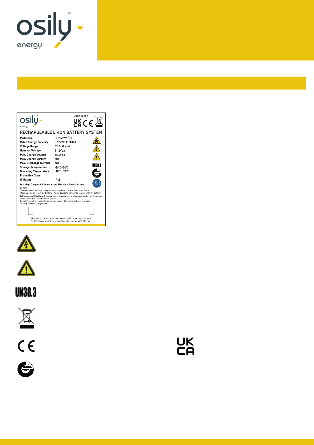
FIG1-1 Battery Energy Storage System nameplate
Battery is voltage higher than safe voltage, direct contact with electric shock hazard.
Be careful with your actions and be award of the dangers.
The battery product meet the United Nations regulations on transport of dangerous goods.
The scrapped battery cannot be put into the garbage can and must be professionally recycled.
This battery product meets European directive requirements.
All the parts of the battery meets TUV safety requirements.

User Manual
LIFEPO4 BATTERY
51.2V 100AH LFP 5KWH/LV
Product Specification
Size and Weight
Table 2-1 LFP 5kWh/ LV Device Model
Performance Parameter
Table 2-2 LFP 5kWh/ LV performance parameter
PRODUCT
SERIES SPECIFICATION
MODEL NOMINAL
VOLTAGE NOMINAL
CAPACITY DIMENSION
(MM) WEIGHT
(KG) IP LEVEL
LFP 5kWh/ LV 5.12V 100Ah 550×700×216 65 IP65
MODULE
TYPE LFP 5KWH/ LV
Total Energy* 5.12kWh
Usable Energy (DC)* 4.6kWh
Nominal Dis-charge Power 3kW
Peak Power(Only Discharge) 7kW for 3 seconds
Voltage 43.2~56Vd.c
Nominal Voltage 51.2Vd.c
Nominal Current 60A
Max. Charge Voltage 58.4Vd.c
Max. Charge Current 60A
Max. Discharge Current 100A
Safety CE UN38.3

User Manual
LIFEPO4 BATTERY
51.2V 100AH LFP 5KWH/LV
Interface Definition
Table 2-3 Interface Definition
This section elaborates on interface functions of the front panel of the device
Figure2-1 LFP 5kWh/ LV the sketch of front interface.
ITEM NAME DEFINITION
1 Negative socket The battery DC output positive pole, which is connected to the negative
pole often inverter through the cable
2 Positive socket The battery DC output negative pole, which is connected to the negative pole often
inverter through the cable.
3 RS485 The RS485 communication interface is used for parallel communication between batteries
4 CAN CAN communication interface is used for communication between battery and inverter
5 LED1 Module capacity status indicator light
6 LED2 Module capacity status indicator light
7 LED3 Module capacity status indicator light
8 LED4 Module capacity status indicator light
9 ADD switch Use the switch to adjust the address when the battery is in parallel mode
10 Reset switch
Press the switch and the battery system turn on. When the battery is in the non use state such as storage,
transportation etc., it need to be turn off by switch button, and the battery system will automatically sleep
after the device without external load power
11 Main switch Open or cut off the main circuit, and ensure transportation safety after cutting off
LFP 5-10kWh/ LV User Manual
- 8 -
Interface Definition
This section elaborates on interface functions of the front panel of the device
Figure2-1 LFP 5-10kWh/ LV the sketch of front interface.
Table 2-3 Interface Definition
Item
Name
Definition
1
Negative socket
The battery DC output positive pole, which is connected to the negative pole often
inverter through the cable.
2
Positive socket
The battery DC output negative pole, which is connected to the negative pole
often inverter through the cable.
3
RS485
The RS485 communication interface is used for parallel communication between
batteries.
4
CAN
CAN communication interface is used for communication between battery and
inverter.
5
LED1
Module capacity status indicator light
6
LED2
Module capacity status indicator light
7
LED3
Module capacity status indicator light
8
LED4
Module capacity status indicator light
9
ADD switch
Use the switch to adjust the address when the battery is in parallel mode.
10
Reset switch
Press the switch and the battery system turn on. When the battery is in the non use
state such as storage, transportation etc., it need to be turn off by switch button, and
the battery system will automatically sleep after the device without external load
power.
11
Main switch
Open or cut off the main circuit, and ensure transportation safety after cutting off
Table 2-4 LED status indicators (Take LFP 10kWh/ LV as an example)
Flashing 1£ bright 0.25s Light out 3.75s
Flashing 2£ bright 0.5s Light out 0.5s
Flashing 3£ bright 0.5s Light out 1.5s
10
5 6 7 8
1
2
3
4
9
11
User Manual
LIFEPO4 BATTERY
51.2V 100AH LFP 5KWH/LV
Battery Management System (BMS)
Voltage Protection
Discharging Low Voltage Protection -
When battery cell voltage is lower than the rated protection
value or total voltage below 42V during discharge over-discharge
protection is activated and the battery alerts the user via alarm.
The battery will then isolate and cut-off. When the voltage of each
cell recovers to rated value and total voltage restored to above
45V, the protection resides.
Charging Over Voltage Protection -
When charging, the system stops charging when the total voltage
of the battery pack is higher than 54.75V or the voltage of any
single cell reaches the protection value. When the total voltage
returns to below 52V and the cell voltage returns to below the
rated protection value, the protection is release.
Temperature Protection
Less/ Over temperature protection in charging:
When the battery’s temperature is beyond range of 0~+45
during charging, temperature protection is enforced and
device stops charging. The protection is released when it
recovers to rated return range.
Less/ Over temperature protection in discharging:
When battery’s temperature is beyond range of -10~+45
during discharging, temperature protection starts and the
device stops supplying power to the outside. The protection
is released when it recovers to rated return range.
Other Protection
Short Circuit Protection:
When the battery is activated from the off state, if a short circuit
occurs, the DC circuit breaker will act first. If the DC circuit
breaker does not operate, the BMS will start the short circuit
protection function and cut off the external voltage output.
Self Shutdown:
When device connects no external loads for over 72 hours
the device will activate dormant standby automatically.
Caution:
The maximum working current of the load which needs to be
powered should be less than the maximum discharge current
capacity of the battery system
Current Protection
Over Current Protection in Charging -
When the charging current is greater than the protection value an
internal alarm is activated and the system stops charging. After the
system delays the rated time for 1 min, the protection is released.
Over Current Protection in Discharging:
When the discharging current is greater than the protection value, the
battery signals an alarm and the system stops discharging. After the
system delays the rated time for 1 min, the protection is released.
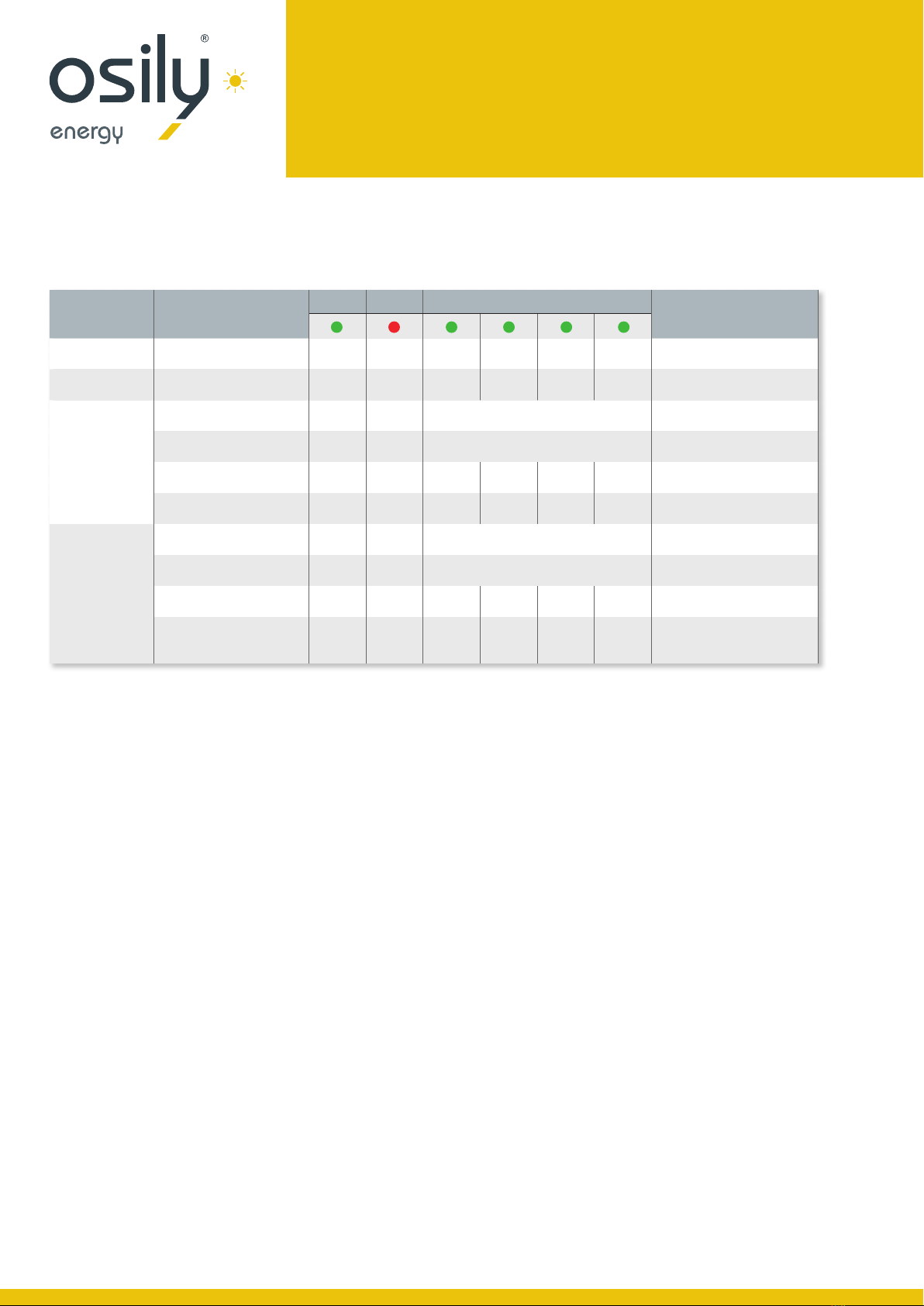
SYSTEM
STATE RUNNING
STATE
RUN ALM SOC
EXPLAIN
Shut down Dormancy OFF OFF OFF OFF OFF OFF ALL OFF
Standby Normal Flashing 1 OFF OFF OFF OFF OFF
Charging
Normal Flashing 1 OFF According to the power prompt
Over current
alarm Flashing 1 Flashing 2 According to the power prompt
Over voltage
protection Flashing 1 OFF OFF OFF OFF OFF
Temperature Over current
protection Flashing 1 Flashing 1 OFF OFF OFF OFF
Discharge
Normal Flashing 3 Flashing 3 According to the power prompt
Alarm Flashing 3 Flashing 3 According to the power prompt
Temperature, Over current,
Short circuit protection OFF OFF OFF OFF OFF OFF Stop discharge, Mains offline
48h no action forced sleep
Under voltage protection OFF OFF OFF OFF OFF OFF Stop discharge
Flashing 1 = bright 0.25s Light out 3.75s
Flashing 2 = bright 0.5s Light out 0.5s
Flashing 3 = bright 0.5s Light out 1.5s

User Manual
LIFEPO4 BATTERY
51.2V 100AH LFP 5KWH/LV
Installation Safety
• The safety regulations and local safety regulations listed below should always be followed during the installation.
• All circuits connected to this power system with an external voltage of less than 48V must meet the SELV requirements
defined in the IEC60950 standard.
• If operating within the power system cabinet, make sure the power system is not charged. Battery devices should also be
switched off.
• Distribution cable wiring should be reasonable and has the protective measures to avoid touching these cables while
operation power equipment.
• When installing the battery system, please wear the protective items below:
Environmental Requirements
• Working temperature: -10OC~+50OC
• Charging temperature range is 0OC~+45 OC,
• Discharging temperature range is -10 OC ~+50 OC
• Relative humidity: 4%~100%RH (No condensed water)
• Elevation: no more than 4000m
• Operating environment: Indoor or outdoor installation, sites avoid the sun and no wind,
no conductive dust and corrosive gas.
And the following conditions are met:
• Installation location should be away from the sea to avoid brine and high humidity environment.
• The ground is flat and level.
• There is no flammable explosive near to the installation places.
• The optimal ambient temperature is +15OC~+30OC.
• Keep away from dust and dirty areas.
Gloves Safety Glasses Safety Shoes
Installation and Configuration
Electrical Interface Check
Devices that can be connected directly to the battery can be user equipment, power supplies, or other power supplies.
• Confirm whether the user equipment, the PV equipment or other power supply equipment has the DC standby interface,
and measure whether the output voltage of the standby interface meets the requirements of the voltage range of table 2-2.
• Verify that the maximum discharge current capacity of the user equipment, the PV equipment or other power supplies, the DC standby
interface, and the maximum discharge current shall be greater than the maximum charging current of the products used in table 2-2.
• If the user equipment DC prepared interface maximum discharge capacity is less than the maximum charging current products using
table 2-2, the user interface should have the power equipment of DC current limiting function, give priority to ensuring the normal work
of user equipment.
User Manual
LIFEPO4 BATTERY
51.2V 100AH LFP 5KWH/LV
Attention should be paid to the following items before construction:
• Power line specification.
• The power line specification shall meet the requirements of maximum discharge current for each product.
• Mounting space and bearing capacity.
• Make sure that the battery has enough room to install, and that the battery rack and bracket have enough load capacity.
The wall for battery installation shall be solid brick or cement wall with strong bearing capacity and wall
thickness no less than 100mm.
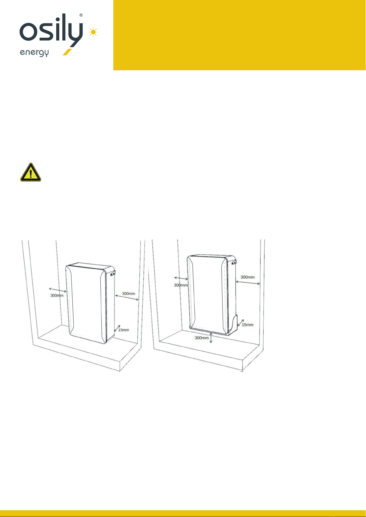
Mounting space requirements:
Equipment installation:
Strongly recommended: floor installation;
If it is wall-mounted installation, strictly follow the requirements below.
LFP 5-10kWh/ LV User Manual
- 12 -
Attention should be paid to the following items before construction:
• Power line specification.
• The power line specification shall meet the requirements of maximum discharge current for each product.
• Mounting space and bearing capacity.
• Make sure that the battery has enough room to install, and that the battery rack and bracket have enough load capacity.
• Make sure the power line and ground wire are reasonable. Not easy to short-circuit, water and corrosion.
Equipment installation:
SStrongly recommended: floor installation;
If it is wall-mounted installation, strictly follow the requirements below.
The wall for battery installation shall be solid brick or cement wall with strong bearing capacity and wall thickness no less than 100mm.
Mounting space requirements:
Floor installation Mounted on the wall installation
User Manual
LIFEPO4 BATTERY
51.2V 100AH LFP 5KWH/LV
When the battery system is placed directly on the ground, a fixed support must be
used to fix the top of the battery box with the wall.
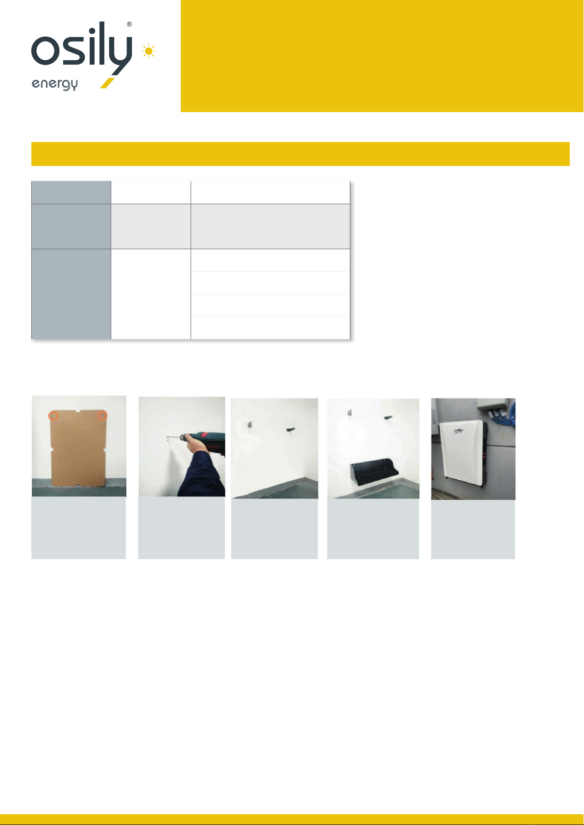
Use the positioning
carboard to draw
screw hole positions
on the wall
Drill 4 holes, hole
depth greater
than 70mm for
expansion bolts.
Attach the fixings
using the M6 bolts,
Torque at 6NM.
(Floor installation)
Install the battery
bracket with M6
expansion bolts
(Wall installation)
Slot the battery
onto top rack (floor)
or hoist battery
(wall mount)
Installation
STEP 1 System outage Ensure that the battery is in a shutdown state
STEP 2 Mechanical
installation
1. Hanger mounting
2.Equipment installation
STEP 3 Electrical
installation
1. Connect the ground cable
2. Electrical installation
3. Connect inverter
4. Communication interface connection
Electrical installation
Before connecting the power cables, using a multimeter to measure cable continuity, short circuit, confirm positive and negative, and mark
well the cable labels.
Measuring methods:
• Switch off cables: select the buzzer and use the probe to measure the ends of the same color cable. If the buzzer calls, it means the
cable is available.
• Short circuit judgment: choose multimeter resistor file, probe the same end of positive and negative pole, if the resistor shows infinity,
means that the cable is available.
After visual testing of power line is connected well, the positive and negative poles of the battery shall be connected respectively to the
positive and negative poles of another device
User Manual
LIFEPO4 BATTERY
51.2V 100AH LFP 5KWH/LV
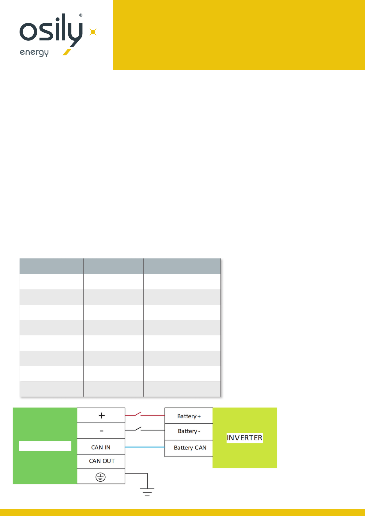
Communication port interface
Connect the CAN Cable of the battery to the CAN communication interface of the inverter using the RJ45 cable.
Factory default CAN communication mode.
Table 3-3 PIN Definition
FOOT POSITION COLOUR DEFINITION
PIN1 Orange/ White 485A
PIN2 Orange XGND
PIN3 Green/ White 485B
PIN4 Blue CANH
PIN5 Blue/ White CANL
PIN6 Green NC/NULL
PIN7 Brown/ White XIN
PIN8 Brown NC/NULL
LFP 5kWh/LV
• When connecting the battery and the inverter, please use the appropriate power and communication cables, these
accessories are provided in the box when unpackaging the unit.
• Keep the battery system on standby, connect the power cable to the interface on the input side of the inverter first,
and then connect the power cable to the interface on the battery side.
• The battery out put interface is a quick connector, and the power cable (Positive, Negative) plug can be directly inserted
into the battery socket.
Connected inverter
When the system is used independently:
Note: Before installation, please confirm whether the DIP switch mode of No.1 module in battery is correct according to the
inverter used. For specific dialing methods, please refer to “3.4.2 battery module DIP switch definition and description.”
Except for the inverter specified by the customer’s special requirements, the factory default DIP switch mode of Module No.1
is DIP Switch model 1( ADD: 0000). If the inverter is equipped with other DIP switch mode, open the cover and set DIP switch
mode of the module No.1 to the correct mode.

User Manual
LIFEPO4 BATTERY
51.2V 100AH LFP 5KWH/LV
Battery module DIP switch definition and description
Table3-4-1 Slave setting Table3-4-2 Host setting (Table 2)
ADDRESS DIP SWITCH POSITION INSTRUCTION
#1 #2 #3 #4
1ON OFF OFF OFF Slave 1
2 OFF ON OFF OFF Slave 2
3ON ON OFF OFF Slave 3
4 OFF OFF ON OFF Slave 4
5ON OFF ON OFF Slave 5
6 OFF ON ON OFF Slave 6
7ON ON ON OFF Slave 7
8 OFF OFF OFF ON Slave 8
9ON OFF OFF ON Slave 9
10 OFF ON OFF ON Slave 10
11 ON ON OFF ON Slave 11
12 OFF OFF ON ON Slave 12
13 ON OFF ON ON Slave 13
14 OFF ON ON ON Slave 14
15 ON ON ON ON Slave 15
NUMBER OF SLAVES
CONNECTED DIP SWITCH POSITION TOTAL
#5 #6 #7 #8
1ON OFF OFF OFF parallel 2
2 OFF ON OFF OFF parallel 3
3ON ON OFF OFF parallel 4
4 OFF OFF ON OFF parallel 5
5ON OFF ON OFF parallel 6
6 OFF ON ON OFF parallel 7
7ON ON ON OFF parallel 8
8 OFF OFF OFF ON parallel 9
9ON OFF OFF ON parallel 10
10 OFF ON OFF ON parallel 11
11 ON ON OFF ON parallel 12
12 OFF OFF ON ON parallel 13
13 ON OFF ON ON parallel 14
14 OFF ON ON ON parallel 15
15 ON ON ON ON parallel 16

User Manual
LIFEPO4 BATTERY
51.2V 100AH LFP 5KWH/LV
Table3-4-3 Parallel dialing code setting example (Table 3)
NUMBER OF PARALLEL
MACHINES
SLAVE DIP SWITCH HOST DIP SWITCH
INSTRUCTION
#1 #2 #3 #4 #5 #6 #7 #8
Stand alone use OFF OFF OFF OFF OFF OFF OFF OFF
Parallel 2
OFF OFF OFF OFF ON OFF OFF OFF
ON OFF OFF OFF OFF OFF OFF OFF
Parallel 3
(see diagram below)
OFF OFF OFF OFF OFF ON OFF OFF
ON OFF OFF OFF OFF OFF OFF OFF
OFF ON OFF OFF OFF OFF OFF OFF
| |||||||| |
| |||||||| |
Parallel 16
OFF OFF OFF OFF ON ON ON ON First host
ON OFF OFF OFF OFF OFF OFF OFF Second slave
OFF ON OFF OFF OFF OFF OFF OFF Third slave
ON ON OFF OFF OFF OFF OFF OFF Forth slave
OFF OFF ON OFF OFF OFF OFF OFF Fifth slave
ON OFF ON OFF OFF OFF OFF OFF Sixth slave
OFF ON ON OFF OFF OFF OFF OFF Seventh slave
ON ON ON OFF OFF OFF OFF OFF Eighth slave
OFF OFF OFF ON OFF OFF OFF OFF Ninth slave
ON OFF OFF ON OFF OFF OFF OFF Tenth slave
OFF ON OFF ON OFF OFF OFF OFF Eleventh slave
ON ON OFF ON OFF OFF OFF OFF Twelfth slave
OFF OFF ON ON OFF OFF OFF OFF Thirteenth slave
ON OFF ON ON OFF OFF OFF OFF Fourteenth slave
OFF ON ON ON OFF OFF OFF OFF Fifteenth slave
ON ON ON ON OFF OFF OFF OFF Sixteenth slave
DIP switch description
When the battery pack is connected in parallel, the host can communicate with the slave(s) through the RS485 interface.
The host summarises the information of the entire battery system and communicates with the inverter through CAN.
Example connection
User Manual
LIFEPO4 BATTERY
51.2V 100AH LFP 5KWH/LV
Battery system usage and operation instructions
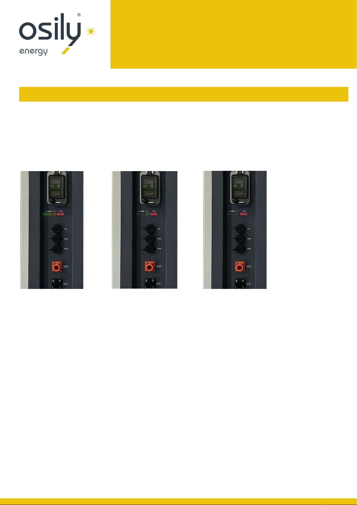
After completing the electrical installation, follow these steps to start the battery.
• Press the switch, the system self-check, the indicator lights turn on successively (4.1.1).
• The RUN indicator blinks slowly if the battery is not connected to the inverter (4.1.2).
• If the battery is connected with the inverter, the battery start working and the indicator lights up (4.1.3).
Note:
After pressing the power button the status indicator on the front panel continues to indicate red, please
refer to the “4.2 Alarm description and processing”. If the failure cannot be eliminated, please contact your supplier.
• Use a voltmeter to measure whether the voltage across the BAT+/ BAT- terminals of the inverter is greater than 42V,
and check whether the voltage polarity is consistent with the input polarity of the inverter. If the voltage across the
terminals BAT + / BAT- of the inverter is greater than 42V, at this time the battery has begun to work normally.
• After confirming that the battery output voltage and polarity are correct, turn on the inverter, then close
the circuit breaker switch.
• Check whether the indicator light of the inverter and the battery connection ( The communication indicator and
the battery access status indicator.) is in normal condition. If normal, the connection between the battery and the
inverter is completed. If there is an abnormity in the indicator light.
Use, maintenance and troubleshooting
LFP 5-10kWh/ LV User Manual
- 18 -
Use, maintenance and troubleshooting
Battery system usage and operation instructions
After completing the electrical installation, follow these steps to start the battery.
• Press the switch, the system self-check, the indicator lights turn on successively (4.1.1).
• The RUN indicator blinks slowly if the battery is not connected to the inverter (4.1.2).
• If the battery is connected with the inverter, the battery start working and the indicator lights up (4.1.3).
4.1.1
4.1.2
4.1.3
Note:
After pressing the power button the status indicator on the front panel continues to indicate red, please refer to the “4.2 Alarm description and
processing”. If the failure cannot be eliminated, please contact Osily.
• Use a voltmeter to measure whether the voltage across the BAT+/ BAT- terminals of the inverter is greater than 42V, and check whether the
voltage polarity is consistent with the input polarity of the inverter. If the voltage across the terminals BAT + / BAT- of the inverter is greater
than 42V, at this time the battery has begun to work normally.
• After confirming that the battery output voltage and polarity are correct, turn on the inverter, then close the circuit breaker switch.
• Check whether the indicator light of the inverter and the battery connection ( The communication indicator and the battery access status
indicator.) is in normal condition. If normal, the connection between the battery and the inverter is completed. If there is an abnormity in the
indicator light, please check the reason or contact the local dealer with the inverter manual

User Manual
LIFEPO4 BATTERY
51.2V 100AH LFP 5KWH/LV
Alarm description and processing
When protection start or failure, the ALM indicator on the side panel will alarm, through net management can
query specific alarm class and take appropriate action.
Alarm and countermeasure influence system output
If there are any abnormalities affecting the output, such as battery cell over-voltage or over-current during charge
/ discharge, undervoltage protection and temperature protection protocols should be followed, please deal with
them according to Table 4-1.
Alarm and countermeasure without affecting the output of the system
If a low SOC alarm occurs, the battery system also issues a corresponding alarm signal. Maintainer should
check the equipment and determine the type and location of the fault. Ensure the correct countermeasures
are carried out so that the system is in the best working condition to avoid disrupting future power distribution.
The countermeasures are shown in Table 4-2.
Table 4-1 Main alarm and Protection
Table 4-2 minor alarm
STATUE ALARM CATEGORY ALARM INDICATION PROCESSING
Charging State
Cell over-voltage RUN light flashing 1 Stop charging and release when
discharging
Over-current when
charging Run light on RED flashing 2 Reduce the charging current below
the rated value
High temp protection RED light flashing 1 Stop charging and find out the
cause of the trouble
Discharge State
Over-current protection
when discharge RED light on Stop discharge and reduce discharge
current below rated value
High temp protection
when discharge RED light on Stop discharging and find out the
cause of the trouble
Total voltage under
voltage protection ALL lights OFF successively Start charging
ALERT CATEGORY ALARM INDICATION COUNTERMEASURE
5%SOC≤ 10% System operating status: The
indicator blinks red slowly Stop discharge and charging
the battery system in time.

User Manual
LIFEPO4 BATTERY
51.2V 100AH LFP 5KWH/LV
Analysis and treatment of common faults
Analysis and treatment of common faults in the Table 4-3:
Table 4-3 Analysis and treatment of common faults
ITEM FAULT PHENOMENON REASON ANALYSIS SOLUTION
1The indicator does not respond
after power on the system Make sure press and hold the
power switch (Reset switch) for 3s Check the power switch
2No DC output after power
on the system Check if the main cable is inserted
into the installation position Check and ensure the main cable
is firmly inserted
3No DC output and red
light flashing Battery voltage is too low Charging the battery system
4The battery cannot be fully
charged. Charging voltage is too low Adjust charging voltage
within 53.5V range
5The power line sparks once power on
and ALM indicated Red light on Power connection short-circuit Turn off the battery, check the
cause of the short circuit
This manual suits for next models
1
Table of contents


