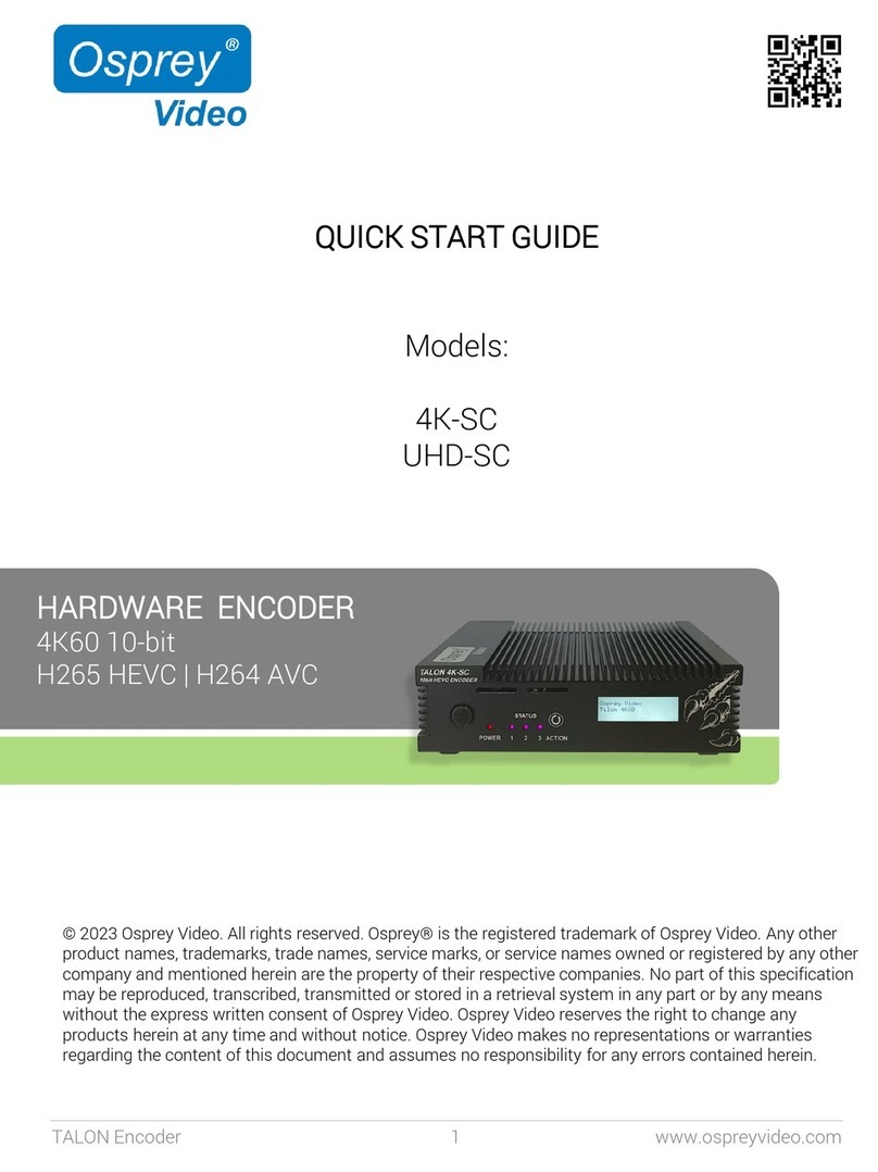
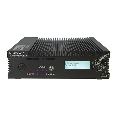
osprey video Talon PRO User manual

Page 1of 59
Talon PRO User Guide
02/26/2020

Page 2of 59
© 2019 Osprey Video. All rights reserved.
Osprey® is the registered trademark of Osprey Video. Microsoft®, Windows® is a registered trademark of Microsoft Corporation. Any other
product names, trademarks, trade names, service marks, or service names owned or registered by any other company and mentioned herein
are the property of their respective companies.
No part of this specification may be reproduced, transcribed, transmitted or stored in a retrieval system in any part or by any means without
the express written consent of Osprey Video. Osprey Video reserves the right to change any products herein at any time and without notice.
Osprey Video makes no representations or warranties regarding the content of this document and assumes no responsibility for any errors
contained herein.
OVERVIEW
Thank you for purchasing the Osprey® Talon PRO video encoder from Osprey Video. This user guide provides step-by-step
instructions for installing and using your new video encoder. For the latest Osprey product information and news, visit our
website at www.ospreyvideo.com.
FEEDBACK:
We greatly value your input. Please direct any questions, comments or support issues to
support@ospreyvideo.com
+1 972 488 7156
PRODUCT DESCRIPTION
The Osprey Talon PRO is a hardware based, small form-factor video encoder designed to be easy to use, portable, and easily
stream 4K, HD or SD content to broadband and mobile networks. It supports 2 simultaneous inputs (3 total) and can stream
HEVC or AVC via an extensive array of transports. Its versatility makes it an excellent Cloud Contribution Encoder. It has an
intuitive web interface for configuration.

Page 3of 59
OVERVIEW 2
FEEDBACK: 2
PRODUCT DESCRIPTION 2
FEATURES 6
SUPPORTED INPUT RESOLUTIONS 6
OPERATING CONTROLS 7
QUICK SETUP 9
Connect the encoder 9
Verify the ip address 10
Connect via a browser 10
WEB UI 13
SYSTEM 14
Device 14
Network 17
Security 18
Date & Time 19
Status LED (advanced) 20
Transports 21
Update 22
Reboot 22
STATUS 23

Page 4of 59
WIFI CONFIGURATION 24
ENCODERS CH1, CH2, CH3 25
Set Encoder Settings 25
Start 25
Destination 25
Video 31
Audio 36
CONFIGURING ENCODER FOR RTMP/RTMPS 37
CONFIGURING ENCODER FOR RTP 39
CONFIGURING ENCODER FOR RTSP 41
CONFIGURING ENCODER FOR UDP 42
CONFIGURING ENCODER FOR FACEBOOK™ LIVE 44
CONFIGURING ENCODER FOR WOWZA CLOUD 48
CONFIGURING ENCODER FOR ZIXI™ BROADCASTER 51
CONFIGURING ENCODER FOR STREAMSPOT 52
CONFIGURING ENCODER FOR SRT 53
CONFIGURING H.264(AVC) ENCODING 54
CONFIGURING H.265 (HEVC) ENCODING. 56
Rate Control: VBR or CBR 56
Quality Mode: Low Latency, Balance, High Quality 56
Interlace Mode: Combined, Separated 57

Page 5of 59

Page 6of 59
FEATURES
•Web-Based/Wireless Configuration and Monitoring
•H.265 encode in resolutions up to 2160p30
•H.264 video from QCIF to 2160p30
•H.265, H.264, MJPEG
•Low Latency
•Fully controllable parameters: resolution, max bitrate, GOP and on-the-fly bitrate control
•Zixi Feeder™Support
•SRT Support (Modes Supported: Caller & Sender)
•HE-AAC, HEv2-AAC, AAC-LC
•2 Channels Line Level and Embedded Audio
•Interfaces: HDMI 1.4a input/output, Display Port 1.1 input, 2x 3G-SDI input, Gigabit Ethernet, Re-Clocked
SDI loop through, Line Level Audio input
•Outputs: RTP, RTSP, MPEG-2 TS over UDP, RTMP, RTMPS, Zixi Feeder, SRT, and TSRTP
•MP4 & TS File Recording
•4SDI stereo pairs supported
•Support for Dual HD SDI mode or HD SDI and a HDMI input
•Audio Resampling support
•Live Video Preview in the web browser
•ROI crop encode
•Supports unicast and multicast streaming
•1x USB 2.0 interface for local storage
•1x Micro-SD card interface for local storage
•Operating System: Embedded Linux
•Redundant Power Supply
SUPPORTED INPUT RESOLUTIONS
HDMI (TV): 2160p30, 1080p60, 1080p59.94, 1080p50, 1080p30, 1080p29.97, 1080p25, 1080p24, 1080p23.98, 1080i30, 1080i29.97, 1080i25,
1080i24, 1080i23.98, 720p60, 720p59.94, 720p50, 720p30, 720p29.97,720p25, 720p24, 720p23.98, 576p50, 480p60
NOTE: HDMI 1080I MODES REQUIRE OPERATING MODE HD_INTERLACED IN SYSTEM SETUP TAB
HDMI (PC): 3560x1760 @ 30fps, 2560x1600(WQXGA) @ 25fps, 2560x1600 @ 30fps, 2560x1600 @ 50fps, 2560x1600 @ 60fps, 1920x1200 @
60fps, 1680x1050 @ 60fps, 1600x1200 @ 60fps, 1600x900 @ 60fps, 1440x900 @ 60fps, 1400x1050 @ 60fps, 1280x1024 @ 60fps, 1280x1024
@ 75fps,1280x1024 @ 85fps, 1280x960 @ 60fps, 1280x800 @ 60fps, 1280x768 @ 60fps, 1280x768 @75fps, 1280x768 @ 85fps, 1280x720 @
75fps, 1280x720 @ 85fps, 1280x600 @ 60fps, 1152x864 @ 60fps, 1024x768 @ 60fps, 1024x768 @ 70fps, 1024x768 @ 75fps, 1024x768
@85fps, 960x600 @ 60fps, 848x480 @ 60fps, 800x600 @ 60fps, 800x600 @ 72fps, 800x600 @75fps, 800x600 @ 85fps, 640x480 @ 60fps,
640x480 @ 75fps, 640x480 @ 85fps, 640x360 @ 60fps
SDI:1080p60, 1080p59.94, 1080p50, 1080p30, 1080p29.97, 1080p25, p1080p24, 1080p23.98, 1080i30, 1080i29.97, 1080i25, 1080i24,
1080i23.98, 720p60, 720p59.94, 720p50, 720p30, 720p29.97, 720p25, 720p24, 720p23.98, 576i25, 480i30, 480i29.97

Page 7of 59
OPERATING CONTROLS

Page 8of 59

Page 9of 59
QUICK SETUP
CONNECT THE ENCODER

Page 10 of 59
VERIFY THE IP ADDRESS
1. Use a smart phone
2. Turn on wireless networking
3. Connect to wireless network “Talon-Pro (your Talon serial
number) with password “0spr3yT@l0n”
4. Using the phone’s browser, go to http://10.1.1.1
5. Read the Local IP Address of the Talon Here:
CONNECT VIA A BROWSER
Using a PC, MAC or Tablet that is on the same network as the Talon,
enter the IP address you found above. EXAMPLE
http://192.168.2.21
Select a Channel

Page 11 of 59
Click on the
Destination Bar
Enter Destination Info
Click on the Video Bar
Video Settings
Video Preview

Page 12 of 59
Click on the Audio Bar
Enter Audio Info
Select START

Page 13 of 59
WEB UI
The Web UI can be reached from any modern browser that has access to the network where the Talon PRO
resides. It opens at a landing page that displays information regarding the global system settings. The
informational tabs are SYSTEM, STATUS, and Wi-Fi. Most of the global settings are found beneath the SYSTEM tab.
Before moving on to encoder configuration, familiarize yourself with the basic SYSTEM settings.

Page 14 of 59
SYSTEM
The System tab has device information along with global system settings.
DEVICE
DEVICE INFORMATION

Page 15 of 59
HARDWARE MODEL
TALON-PRO
SERIAL NUMBER
The Device Serial Number is used by other parts of the system to identify this encoder and the features associated
with it. It cannot be changed by the user.
MODE
Indicates whether the encoder is in Multi Input mode, or Single Input mode. The default is Multi Input. This
changes to Single Mode if, in the Streaming Options category below the Ultra Low Latency option is enabled.
DEVICE CONFIGURATION
ADVANCED SETTINGS DISPLAY
The basic encoding settings are enabled by default For greater customization, additional settings may be accessed
by enabling Advanced Settings.
If Enabled, the advanced settings become visible in the UI. The default is Disabled.
SOURCE CONFIGURATION (ADVANCED)
Specifies which source combination is available. Options are:
1. 4K30 HDMI + SDI1
2. SDI1 + SDI2
3. HDMI + SDI1
Options 1 and 2 only support progressive inputs. Option 3 supports 3G HDMI, and SDI as well as interlaced
SDI inputs.
Changing this setting requires a reboot.
NETWORK DISCOVERY
When Enabled this allows the encoder to announce its presence on the network so that it can be discovered by the
configuration utility. The default is Enabled.

Page 16 of 59
RESET SWITCH (ADVANCED)
If this is Enabled, there is a recessed button on the front of the encoder that lets the user reset the system back to
factory settings. You may Disable this to prevent unauthorized resetting of the device. The default setting is
Enabled.
To clear all encoder settings, press and hold the reset button. The six Status LEDs will turn green one at a time.
When they all flash at once, release the button and the system will reboot. All encoder settings will be removed.
Non encoder settings will remain.
To clear all system settings and restore to the last system image, press and hold until the six Status LEDs light
green. Continue to hold the button until the six all change to yellow. When the button is released the encoder will
reboot and all settings will be returned to their factory defaults. This includes network settings.
STREAMING OPTIONS (ADVANCED)
ULTRA LOW LATENCY
Default setting is Disabled. When Enabled reduces the overall encoding latency of Talon. To do this the device runs
in “Single Input Mode”. Only one input can be used. This setting can result in degraded video quality and should
not be used for regular streaming.
Changing this setting requires the system to reboot. Any encoders that are running will be stopped.
I/O (ADVANCED)
ANALOG AUDIO VOLUME
This slider adjusts the incoming volume of a source that is connected to the analog audio input on the front panel.
Moving the slider to the right will increase the volume up to 12db. Moving the slider to the left will pad a loud
input up to 12db.

Page 17 of 59
HDMI OUTPUT SOURCE
Be default the HDMI output on the rear of the Talon displays the signal from the HDMI input. Here you may select
any other source and display it on the HDMI output for monitor purposes. This selection can be changed while
Talon is encoding without effecting the streaming output.
NETWORK
NETWORK CONFIGURATION
DHCP
By default, Talon is set to receive an IP address automatically via DHCP.
STATIC IP
If you do not wish to use DHCP you may uncheck the box and assign a static address manually. Be certain that the
static IP you set is valid before rebooting. Failure can cause Talon to become inaccessible to the web UI. When that
occurs, you can use Talon’s wireless access point to reset the address or use the reset button on the front of the
device to restore the system to original default settings.

Page 18 of 59
SECURITY
SERVICE PORT
To turn off the hardware service port set this to “Disabled”.
DEVICE PASSWORD
You can create a password for the web UI here. If no password is set no login is required. Username is “admin”
and cannot be changed.

Page 19 of 59
DATE & TIME
NTP SERVICE
Talon supports Network Time Protocol (NTP) for clock synchronization on computer networks. It is enabled by
default.
TIME ZONE
For NTP purposes, set this to your local time zone. (continent/location)
SERVER
By default, the server address is set for the outside NTP server. If your network uses a local timeserver, you may
input that address here.

Page 20 of 59
STATUS LED (ADVANCED)
STATUS LED INDICATORS
On the front of the Talon PRO are six user configurable LEDs. These can each be set to light up under a specified
condition. The options are:
•Encoder 1: indicates Encoder 1 is active
•Encoder 2: indicates Encoder 2 is active
•Encoder 3: indicates Encoder 3 is active
•Source Media Mounted: indicates if a USB drive or SD card has been recognized by the OS
•WiFi AP enabled: indicates that the WiFi access point is on.
Table of contents
Other osprey video Media Converter manuals