OSPRI LHDW200S User manual
Shenzhen Ospri Intelligent Technology Co., Ltd.
1
LHDW200S Handheld Wobble
Welding Head
User Manual
Shenzhen Ospri Intelligent Technology Co., Ltd.
Tel: +86 0755-85225225
Fax: 4008266163-19300
Mobile: +86 13915329830
Email: z.shi@sz-osprey.com/mj.chen@sz-osprey.com
Address: 2nF,Bldg.C,East Zone No.10, Shangxue Technology Park, Shenzhen,
China.

Shenzhen Ospri Intelligent Technology Co., Ltd.
2
Dear Users:
Welcome to use LHDW200S handheld wobble welding head
manufactured by Shenzhen Ospri Intelligent Technology Co., Ltd. It is
our great honor to gain your trust in our products.
In order to make you have an overall view of the product, convenient
for your use, we specifically provide the user manual for you, including
product characteristics, structural feature, technical feature, direction for
use, maintenance, etc. It's an essential guide when you use this product.
Please read the user manual carefully before use. I'm sure it will be
helpful for you to use this product. In addition, if you have any questions
during use, please contact us, and we will serve you wholeheartedly.
The contents of User Manual are protected by the Copyright Law.
Without the approval of Shenzhen Ospri Intelligent Technology Co., Ltd,
any organization or individual shall not copy or tamper it by any means
and forms. In order to ensure your safety and the product works normally,
please read the guide book carefully before using.

Shenzhen Ospri Intelligent Technology Co., Ltd.
3
Content
Chapter 1Application Method ......................................................................................................4
Chapter 2 General Introduction....................................................................................................5
2.1 Product Principle ..............................................................................................................5
2.2 Product Parameter............................................................................................................5
2.3 Attention.............................................................................................................................5
Chapter 3 Structure Features.........................................................................................................6
3.1 Product Structure..............................................................................................................6
3.2 Brief Introduction of Components...................................................................................7
3.3 Wiring Diagram of Electric Connection .........................................................................8
3.4 Hose Connection..............................................................................................................13
3.1.1 Cooling Hose.........................................................................................................13
4.1.2Auxiliary Gas Hose...............................................................................................13
3.5 QBH Installation.............................................................................................................14
Chapter 4 Maintenance................................................................................................................16
4.1 Maintenance of Protection Window..............................................................................16
4.1.1 Disassembly of Protection Window ....................................................................17
4.1.2 Cleaning of Protection Window..........................................................................17
Shenzhen Ospri Intelligent Technology Co., Ltd.
4
Chapter 1 Application Method
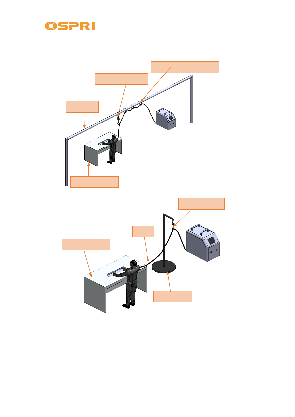
Method 1:
Method 2:
Note:
1) When fiber through the rings, minimum bending radius is 150mm, otherwise
the fiber would be broken possibly. In case place the fiber on the ground, it
would be damaged by trampling things down. It will be uncomfortable to
operate if users don’t hang the optical fiber.
2) The fixed support, rings, extension springs and bellows are not included in our
product package. In case of any demands, please discuss with our sales person.
Attach fiber through the ring
Fixed Tube
Extension Spring
Working Platform
Extension Spring
Fiber
Working Platform
Fixed Support

Shenzhen Ospri Intelligent Technology Co., Ltd.
5
Chapter 2 General Introduction
2.1 Product Principle
The laser beam is generated by the laser, transmitted by the external
optical path, focused by the focusing lens in the welding head, and then
acted on the welded gap between the materials being processed. With the
assist of protective gas (preventing material from being oxidized), the
material is liquefied to form a specific molten pool, so as to achieve the
purpose of welding.
2.2 Product Parameter
Item
Specification
Laser Power
≤2000W
Collimation Length
50mm
Focus Length
100mm
Wobble Oval Spot Size:
1.5mm
NozzleAperture
5 mm
Auxiliary Gas Pressure
<1.0Mpa
Connector Type
QBH
Applicable Laser Brand
Raycus, IPG, etc.
Table 2.2.1
2.3 Attention
Warning: When the laser is used for the product process, please
use a protective device to prevent the damage of the laser beam to
the human body.
Shenzhen Ospri Intelligent Technology Co., Ltd.
6
Chapter 3 Structure Features
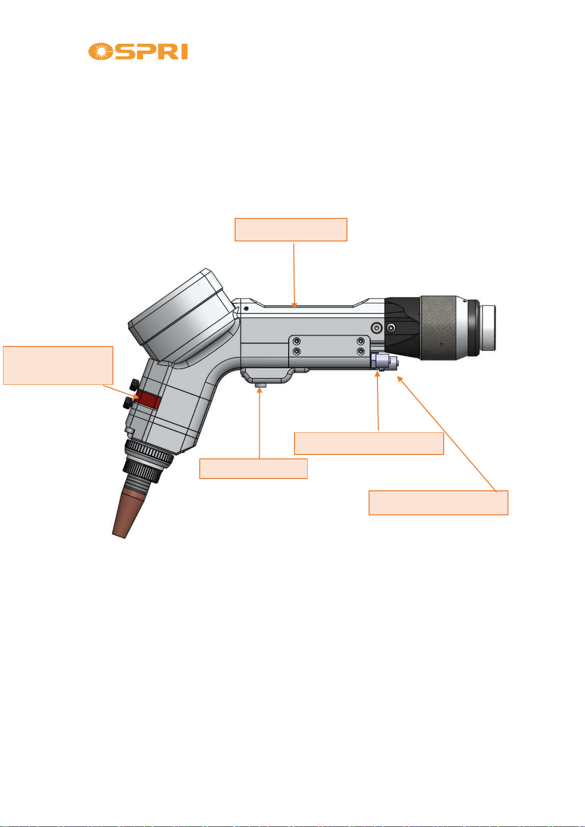
3.1 Product Structure
Diagram 3.1.1
Welding Head Body
Protective Window
Module
Button Switch
Cooling Water Connector
Protection Gas Connector
Shenzhen Ospri Intelligent Technology Co., Ltd.
7
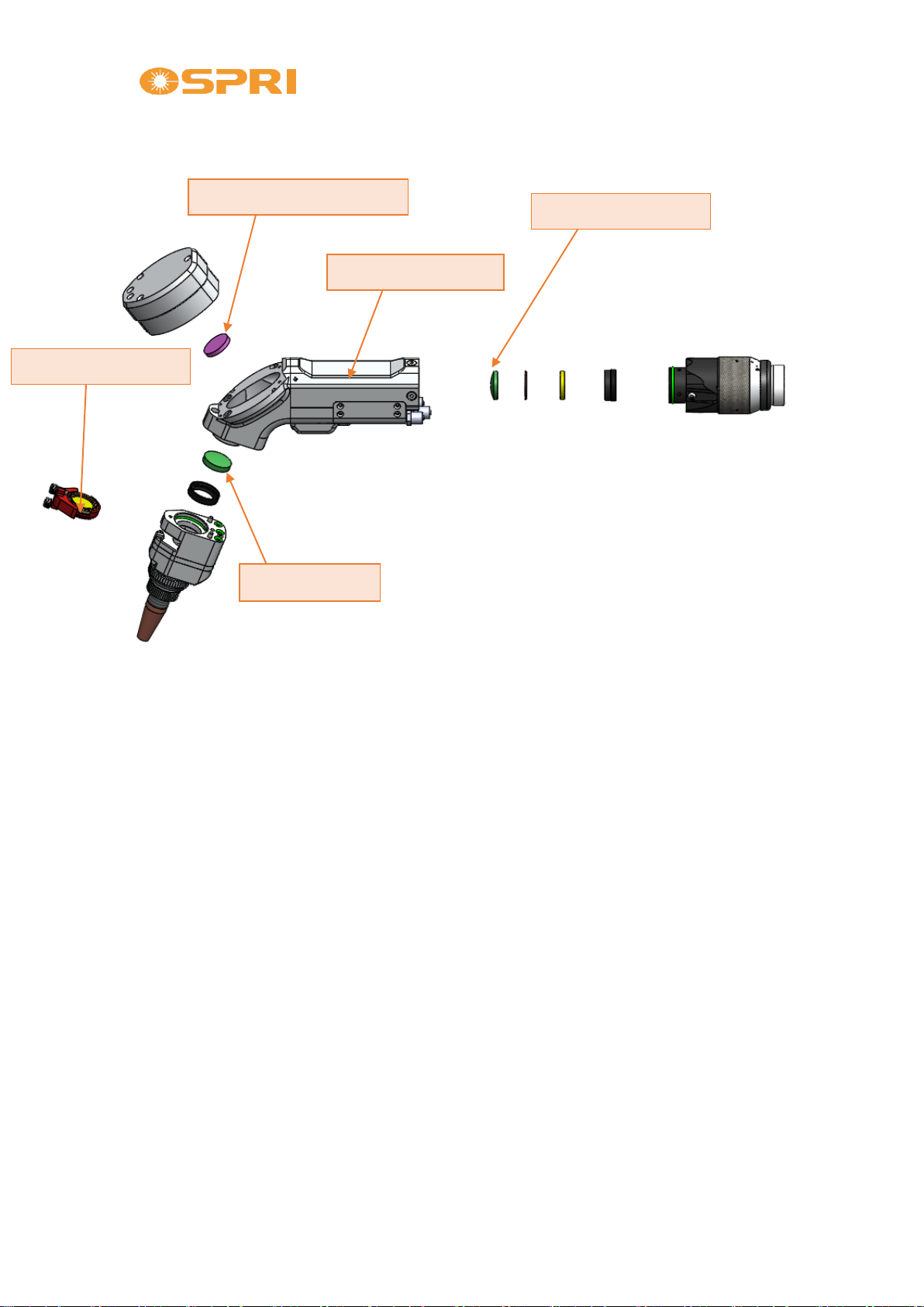
Diagram 3.1.2
Attention:To avoid the dust from falling onto the collimation lens, please
make sure the fiber optic is clean before inserting the fiber.
3.2 Brief Introduction of Components
Welding Head Body: realize QBH locking.
Collimation Lens: to merge divergent beams into a parallel light;
Reflector Mirror: change the direction of beam path.
Focus Lens: Align the parallel beams to form a focused laser.
Protection Window: prevent dust from entering the focus lens and extend
the service life of lens.
Reflector Mirror Module
Welding Head Body
Collimation Lens
Focus Lens
Protection Window
Shenzhen Ospri Intelligent Technology Co., Ltd.
8
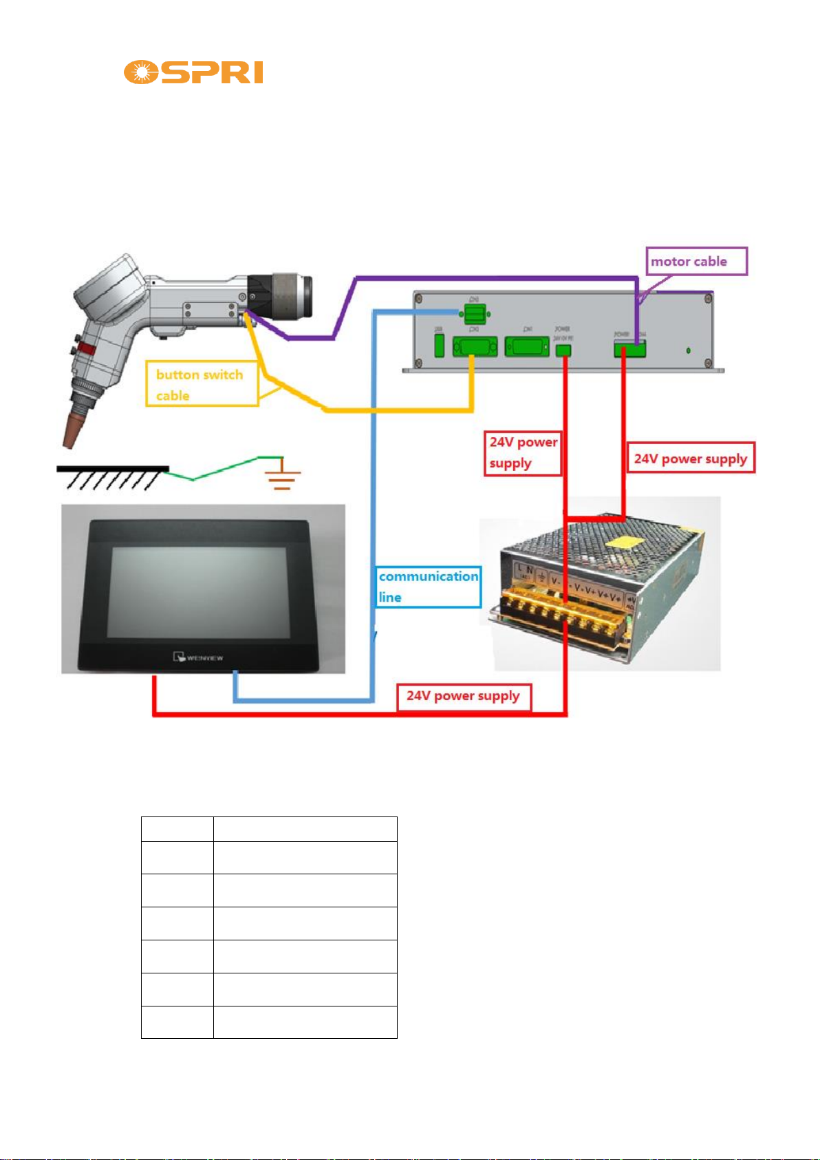
3.3 Wiring Diagram of Electric Connection
LHDW200S Controller Instruction
1. Controller Box Wiring Diagram
2. Controller Box Wiring Definition:
A. CN1(DB15 Female)
PIN
DEFINITION
1.
DA+
9.
DA-
4.
PWM+
13.
PWM-
3.
Laser Enable
11.
Red Laser

Shenzhen Ospri Intelligent Technology Co., Ltd.
9
15.
24V
8.
24V
12.
0V
PIN 1, 9: given DA signal, to control the peak power of laser source;
PIN 4, 13: PWM signal, to control the duty cycle of laser output;
PIN 3, 11: control the laser enable and red laser, signal is PNP output;
PIN 15, 8: 24V power output of the controller;
PIN12: 0V power output of the controller.
B. CN2(DB15 Male):
PIN
DEFINITION
1.
switch signal (of the welding head)
9.
foot pedal signal
2.
nozzle touched signal (of the welding head)
3.
protective gas solenoid valve
14.
0V
7.
0V
15.
24V
8.
24V
PIN 1: switch (button) signal of the handheld welding head, directly
connect to the yellow wire of the head;
PIN 2: nozzle touched signal, directly connect to the green wire;
PIN 9: foot pedal signal, directly connect to the pedal switch or 0V;
PIN 3: protective gas solenoid valve output signal, PNP type;

Shenzhen Ospri Intelligent Technology Co., Ltd.
10
PIN 14, 7: 0V output of the controller;
PIN 15, 8: 24V output of the controller;
C. CN3(DB9 Female):
Connect to the 7-inch touched control screen
D. CN4(3 pins plug):
Connect to the U, V, and W of wobbler motor
E. CN5(2 pins plug):
24V:Connect to switch power 24V;
0V:Connect to switch power 0V;
F. POWER(3 pins plug):
24V:Connect to switch power 24V;
0V:Connect to switch power 0V;
PE: grounded connect;

Shenzhen Ospri Intelligent Technology Co., Ltd.
11
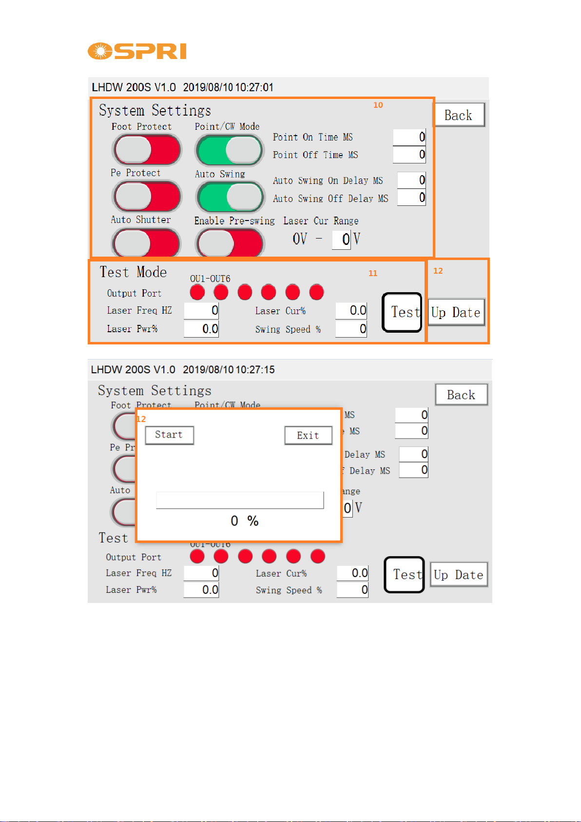
3. Screen Operation Instruction
A. Main Interface
1. Process Layer: There are 20 groups of process parameters to choose, from
No.1~No.20. Each group of parameters can be saved separately.
2. Laser Source Power Parameter:
Peak power ---to limit the peak power of laser output, set from 0~100%;
Laser Freq.Hz ---set the frequency of laser output;
Laser Pwr%---set ratio of laser output per unit time, from 0~100%.
3. On gas delay---blow the protective gas for setting time before the laser
output;
Off gas delay---after laser stops, continue to blow protective gas for setting
time.
4. Pwr Ramp and Pwr Reduce---the time when peak laser power rises or falls
from 0 to the setting peak power.
5. It is wobbling speed and direction of motor
6. It can be operated on the panel to open the laser shutter, red laser, gas
blowing and wobble;
7. System parameters display;
8. Enter advanced parameter settings;
9. Language select;
Shenzhen Ospri Intelligent Technology Co., Ltd.
12
B. Parameter Setting Interface:
1. Set protective function
If foot pedal protection and grounded protection are cancelled, CN1
Pin 1, 9 and Pin 4, 13 will output signal when press switch button;
Auto laser shutter enable. When press the welding head switch
button, laser shutter will open by default;
Auto wobble enable. When press the welding head switch button,
system will auto control the wobbling of motor. When the button
Shenzhen Ospri Intelligent Technology Co., Ltd.
13
released, the system will auto stop the wobbling.
Start re-wobble. The motor will go on wobbling at a low speed;
Point/CW Mode---control whether laser output at intervals during
the laser output.
2. The test mode is to check whether the IO port is normal or not. It should
not be used unless in special occasion. When new function is developed,
the controller box can be upgrade by updated program.
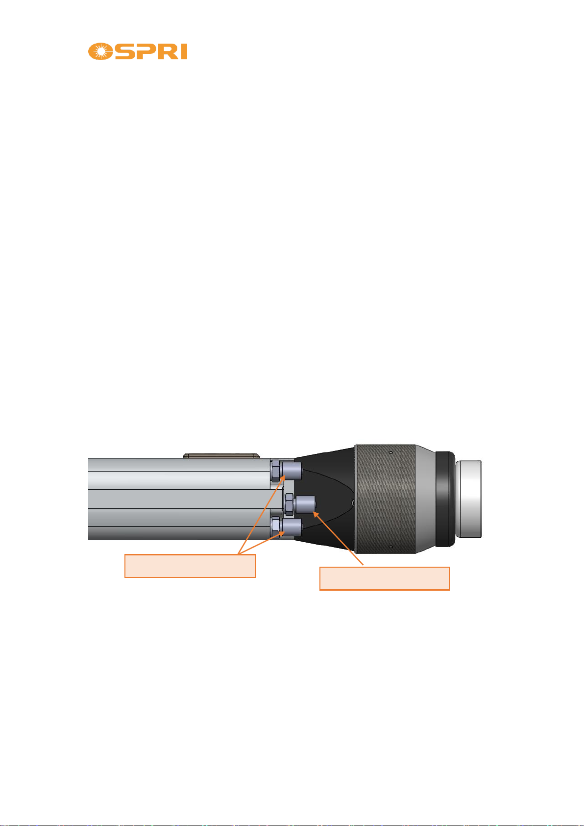
3.4 Hose Connection
3.1.1 Cooling Hose
One interface is connected to the water inlet hose and the other
connected to the outlet hose because a water cooling system is
integrated into a system inside the welding head body.
4.1.2 Auxiliary Gas Hose
Protective gas hose, input pressure <1.0Mpa.
gas hose connector
water hose connector

Shenzhen Ospri Intelligent Technology Co., Ltd.
14
3.5 QBH Installation
①Place the welding head horizontally, remove the dust-proof sealing plug
and dust-proof cover.
②Put the dust-proof sealing plug into the fiber tip protective cover.
③Put the dust-proof cover onto the fiber tip. As below shown:
Attention:In case the fiber tip is equipped with a dust-proof gasket
originally, the original dust-proof gasket still shall be installed.
Otherwise it will affect the sealing performance. It can also cause the
parallel light to turn into the divergent light, which affects the welding effect.
dust-proof cover
dust-proof sealing plug
fiber tip cover
Shenzhen Ospri Intelligent Technology Co., Ltd.
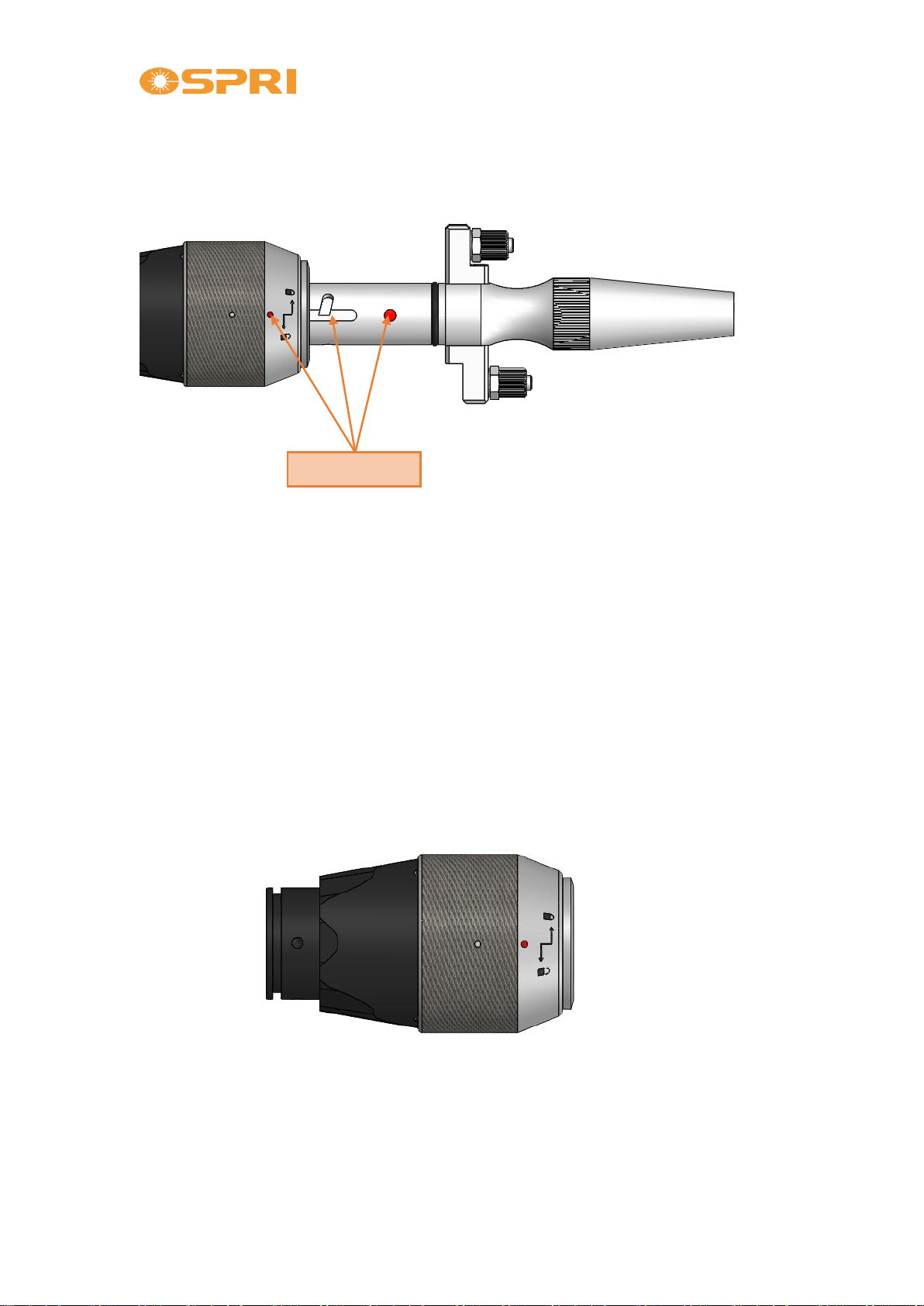
15
⑤Align the red dot on the fiber head with the red dot on the QBH
connector, and slowly insert the fiber tip into the QBH connector.
⑥Turn the QBH connector to the locked state, that is, screw it toward
the limit position clockwise (where can hear a “thud” sound). Then lift
the swivel nut up and screw the nut clockwise again until the fiber tip
is compressed tightly. (Clockwise: toward the direction of the
“locked” icon)
red dot mark

Shenzhen Ospri Intelligent Technology Co., Ltd.
16
Chapter 4 Maintenance
4.1 Maintenance of Protection Window
The protection window locates under the focus lens module. The
protection window will be damaged when there is impurities or foreign
matters on the surface of it. Therefore, it’s necessary to clean the
protection window regularly once a week. Meanwhile, the protection
window is consumable part and needs to be replace when it is damaged.
Note: When cleaning and replacing the protection window,
avoid contaminating it with the oil stain on hands or dust in the
surrounding.

Shenzhen Ospri Intelligent Technology Co., Ltd.
17
4.1.1 Disassembly of Protection Window
①Pull out the protection window drawer from the welding head
body, remove it to clean and dust-free environment, and seal the head
body at the same time.
4.1.2 Cleaning of Protection Window
①Available tools: dust-free wiping swabs, isopropyl alcohol and
rubber air blow.
②Spray isopropyl alcohol onto the dust-free wiping swabs.
③Gently pinch the both sides of the lens with the left thumb and
index finger.
④Hold the wiping swabs with right hand to gently wipe both sides
of the lens in a single direction from bottom to top or from left to
right, and blow the lens surface with the rubber air blow to
confirm that there is no foreign matters on the cleansed lens
surface.
clamp ring
protection window
Table of contents
Other OSPRI Welding Accessories manuals

Popular Welding Accessories manuals by other brands


Lincoln Electric
Lincoln Electric Outershield datasheet

ESAB
ESAB SDF-250 instruction manual

Lincoln Electric
Lincoln Electric VIKING 4C 3350 Series Operator's manual

MICRO-AIR
MICRO-AIR XA23 Max Installation and operation manual

Abicor Binzel
Abicor Binzel ABIROB W50 Instruction leaflet

Aerservice Equipments
Aerservice Equipments ARMOTECH Instruction manual for use