Aerservice Equipments ARMOTECH Instruction manual

ARMOTECH
Rev 02.00
Pag. 1 di 24
©| Aerservice Equipments S.r.l. | 2021 all rights reserved è vietata la riproduzione del presente manuale, anche parziale.
INSTRUCTION MANUAL
FOR USE
AND MAINTENANCE

ARMOTECH
Rev 02.00
Pag. 2 di 24
©| Aerservice Equipments S.r.l. | 2021 all rights reserved è vietata la riproduzione del presente manuale, anche parziale.
CONTENTS
Par
Descrizione
0
Analytical index of the operating and maintenance manual
CONTENTS.........................................................................................................................2
Analytical index of the operating and maintenance manual ..................................................2
GENERAL INFORMATION.................................................................................................3
Manufacturer’s identification data ...........................................................................................3
Machine identification and data plates (if they are present) ..................................................4
Declarations...............................................................................................................................4
UK Declaration of Conformity (UKCA).....................................................................................6
THE SUCTION ARM ARMOTECH......................................................................................7
Description of the arm ..............................................................................................................7
Technical data ...........................................................................................................................9
ASSEMBLY OF THE ARM ARMOTECH..........................................................................11
Assembly.................................................................................................................................11
TYPES OF WALL BRACKET ...........................................................................................14
Description types of wallbracket:...........................................................................................14
FIRST START ...................................................................................................................18
Recommendations ..................................................................................................................18
Normal use...............................................................................................................................19
MAINTENANCE ................................................................................................................20
Ordinary and extra-ordinary maintenance.............................................................................20
DISASSEMBLY AND DISPOSAL.....................................................................................21
Disassembly and disposal......................................................................................................21
OPERATOR’S NOTES......................................................................................................22
Details of maintenance operations ........................................................................................22

ARMOTECH
Rev 02.00
Pag. 3 di 24
©| Aerservice Equipments S.r.l. | 2021 all rights reserved è vietata la riproduzione del presente manuale, anche parziale.
GENERAL INFORMATION
Par
Description
1
Manufacturer’s identification data
MANUFACTURER
Aerservice Equipments S.r.l.
REGISTERED OFFICE –ADMINISTRATIVE OFFICE
Viale dell’industria 24 –35020 –Legnaro –(PD) –Italy
CONTACTS
Tel. +39 049 641 200
E-mail: info@aerservice.com

ARMOTECH
Rev 02.00
Pag. 4 di 24
©| Aerservice Equipments S.r.l. | 2021 all rights reserved è vietata la riproduzione del presente manuale, anche parziale.
GENERAL INFORMATION
Par
Description
2
Machine identification and data plates (if they are present)
Each machine is fitted with a CE plate with indelible identification data. All communications with the
manufacturer or technical assistance centres must refer to the said data.
The position of the plate on the machine may vary.
GENERAL INFORMATION
Par
Description
3
Declarations
The machine is manufactured in conformity with relevant EC Directives applicable when the machine is put
on the market.
ANNEX IV Directive 2006/42/EC
The machine does not belong to the category of machines mentioned in Annex IV to directive 2006/42/EC.
ARMOTECH
Rev 02.00
Pag. 5 di 24
©| Aerservice Equipments S.r.l. | 2021 all rights reserved è vietata la riproduzione del presente manuale, anche parziale.
EC DECLARATION OF CONFORMITY
(Annex IIA DIR. 2006/42/EC)
THE MANUFACTURER
Aerservice Equipments S.r.l.
Company
Viale dell’Industria, 24
35020
Padova
Address
Postal code
Province
Legnaro
Italy
City
Country
DECLARES THAT THE PRODUCT
Articulated suction arm with external structure and rigid tubes
Description
Serial number
Year of manufacture
ARMOTECH
Commercial name
Extraction of welding fumes and microparticles from industrial processes
Intended use
IS IN COMPLIANCE WITH THE FOLLOWING DIRECTIVES
Directive 2006/42/EC of the European Parliament and Council, May 17th 2016, on machinery amending directive 95/16/EC.
Directive 2014/30/EU of the European Parliament and Council, February 26th 2014, on the approximation of the laws of the member States relating
to electromagnetic compatibility.
Directive 2014/35/EU of the European Parliament and Council, February 26th 2014, on the approximation of the laws of the member States relating
to electrical equipment destined to be used within certain voltage limits.
Directive 2011/65/EU of the European Parliament and Council, June 8th 2011, on the restriction of the utilization of certain substances in the electric
and electronic devices. The following harmonized standards have been applied
UNI EN ISO 12100:2010: Safety of machinery - General principles for design - Risk assessment and risk reduction.
UNI EN ISO 13849-1:2016: Safety of machinery - Safety-related parts of control systems - Part 1: General principles for design.
UNI EN ISO 13849-2:2013: Safety of machinery - Safety-related parts of control systems - Part 2: Validation.
UNI EN ISO 13857:2020: Safety of machinery - Safety distances to prevent hazard zones being reached by upper and lower limbs.
CEI EN 60204-1:2018: Safety of machinery - Electrical equipment of machines - Part 1: General requirements.
The complete list of applied standards, guidelines and specifications are available at the manufacturer.
Additional information: The declaration of conformity decays in case of non-compliant use and in the event of
non-confirmed construction changes approved by the manufacturer.
DECLARES THAT THE TECHNICAL FILE
Has been compiled, and is kept and available at the registered office of the company.
Place and date of the document
The manufacturer
Legnaro,
Marco Gallerino

ARMOTECH
Rev 02.00
Pag. 6 di 24
©| Aerservice Equipments S.r.l. | 2021 all rights reserved è vietata la riproduzione del presente manuale, anche parziale.
UK Declaration of Conformity (UKCA)
THE MANUFACTURER
Aerservice Equipments S.r.l.
Company
Viale dell’Industria, 24
35020
Padova
Address
Postal code
Province
Legnaro
Italy
City
Country
DECLARES THAT THE PRODUCT
Articulated suction arm with external structure and rigid tubes
Description
Serial number
Year of manufacture
ARMOTECH
Commercial name
Extraction of welding fumes and microparticles from industrial processes
Intended use
IS IN COMPLIANCE WITH THE FOLLOWING DIRECTIVES
Machinery: The Supply of Machinery (Safety) Regulations 2008.
EMC: Electromagnetic Compatibility Regulations 2016.
LVD: The Electrical Equipment (Safety) Regulations 2016.
RoHS: Restriction of the Use of Certain Hazardous Substances in Electrical and Electronic Equipment Regulations 2012.
The following harmonized standards have been applied
S.I. 2008 No. 1597: Safety of machinery - General principles for design - Risk assessment and risk reduction (ISO 12100:2010)
S.I. 2008 No. 1597: Safety of machinery - Safety-related parts of control systems - Part 1: General principles for design (ISO 13849-1:2015)
S.I. 2008 No. 1597: Safety of machinery - Safety-related parts of control systems - Part 2: Validation (ISO 13849-2:2012)
S.I. 2008 No. 1597: Safety of machinery - Safety distances to prevent hazard zones being reached by upper and lower limbs (ISO 13857:2008)
S.I. 2008 No. 1597: Safety of machinery - Electrical equipment of machines - Part 1: General requirements.
The complete list of applied standards, guidelines and specifications are available at the manufacturer.
Additional information: The declaration of conformity decays in case of non-compliant use and in the event of
non-confirmed construction changes approved by the manufacturer.
DECLARES THAT THE TECHNICAL FILE
Has been compiled, and is kept and available at the registered office of the company.
Place and date of the document
The manufacturer
Legnaro,
Marco Gallerino
ARMOTECH
Rev 02.00
Pag. 7 di 24
©| Aerservice Equipments S.r.l. | 2021 all rights reserved è vietata la riproduzione del presente manuale, anche parziale.
THE SUCTION ARM ARMOTECH
Par
Description
1
Description of the arm
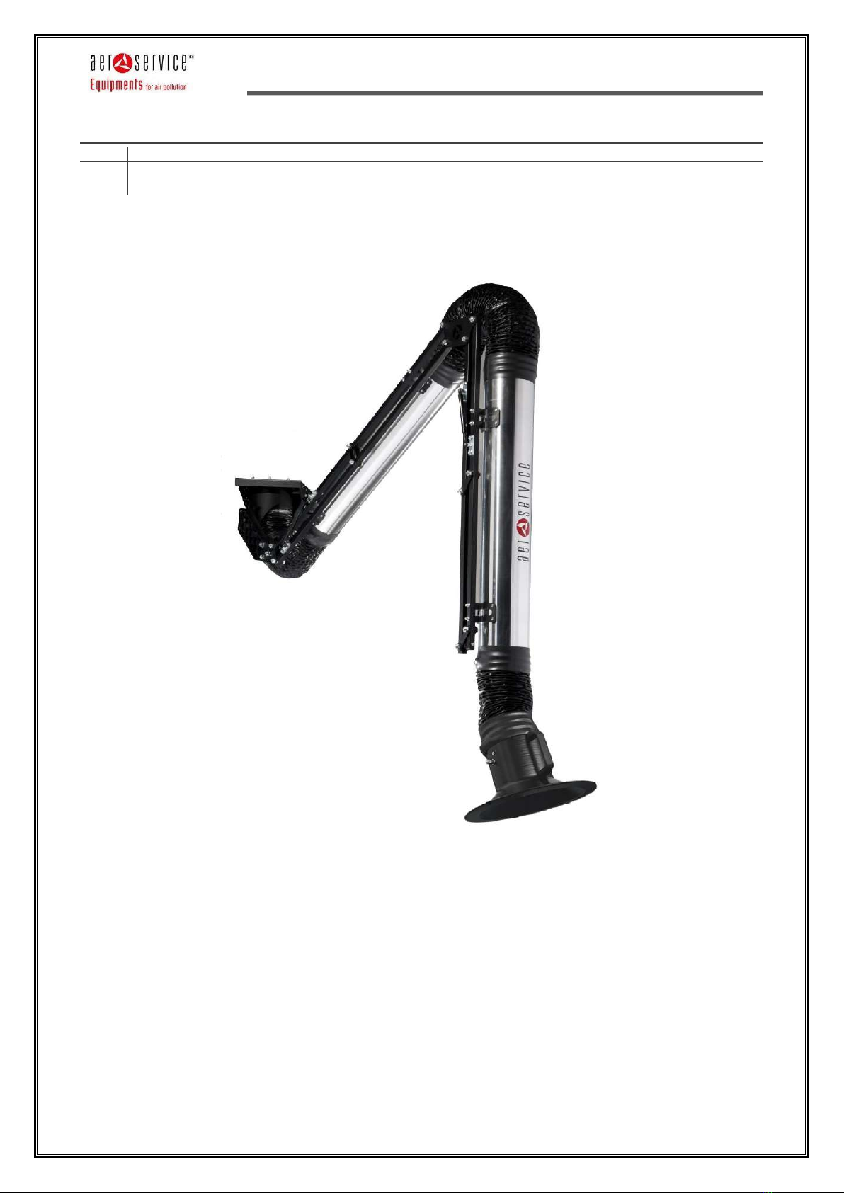
The new ARMOTECH series, thanks to the materials used and the innovative design, allows the operator to
count on high maneuverability, stable positioning and exceptional robustness, guaranteed by a pantograph
structure that supports the arm.
ARMOTECH arm represents the ideal solution for extracting the fumes produced by the various work
operations, in the metalworking, chemical industry, goldsmith laboratories, electronics industry etc. sectors,
capturing fumes as close as possible to the source of pollutant as required by EU regulations and in line with
international standards.
The reduced air flow rates, optimized by the possibility of choosing the type of ARMOTECH most appropriate
to the customer's needs, ease of installation and reduced maintenance, mean that this product increasingly
meets the favor of operators in the sector.

ARMOTECH
Rev 02.00
Pag. 8 di 24
©| Aerservice Equipments S.r.l. | 2021 all rights reserved è vietata la riproduzione del presente manuale, anche parziale.
CAUTION:
During the removal of the packaging, all resulting residues must be disposed of in accordance with
the provisions of the laws in force.
For greater simplicity and better comprehensibility of this manual, some images have been rendered
not exactly in conformity with reality (e.g. dismantled protections).
The installation operations (lifting, fixing, etc.) must be carried out through the use of appropriate
devices and means and in accordance with the Legislative Decree 626/94.
At the end of the installation, it should be checked that there are no exhaust gas leaks in the work
environment. Follow the provisions in force regarding emissions into the atmosphere.
Aerservice Equipments SRL declines all responsibility for damage to persons or things, which could
derive either from an improper use of the appliance or from failure to observe what is prescribed in
this manual.

ARMOTECH
Rev 02.00
Pag. 9 di 24
©| Aerservice Equipments S.r.l. | 2021 all rights reserved è vietata la riproduzione del presente manuale, anche parziale.
THE SUCTION ARM ARMOTECH
Par
Description
2
Technical data
AVAILABLE VERSIONS:
IBSA
Ø
LENGTH
AIR FLOW
HEAD LOSS
WEIGHT
TOT.
mm
mm
m³/h
Pa
Kg
100/2
100
2000
600 - 750
average 700
15
100/3
3000
23
125/2
125
2000
800 - 900
average 700
16
125/3
3000
24
125/4
4000
28
160/2
160
2000
1000 - 1200
average 700
18
160/3
3000
26
160/4
4000
30
IBSAV
Ø
LENGTH
FAN
POWER
EXTRACTION
CAPACITY
ERSIDUAL
PRESSURE
NOISE
WEIGHT
TOT.
mm
mm
mod.
kW
m³/h
Pa
dBA
Kg
100/2
100
2000
EV 15
1,1
750
520
74
31
100/3
3000
39
125/2
125
2000
EV 15
1,1
900
520
74
32
125/3
3000
40
125/4
4000
44
160/2
160
2000
EV 18
1,5
1200
520
74
34
160/3
3000
42
160/4
4000
46
IBSAC
Ø
LENGTH
AIR FLOW
HEAD LOSS
WEIGHT
TOT.
mm
mm
m³/h
Pa
Kg
100/2
100
2000
600 - 750
average 700
15
100/3
3000
23
125/2
125
2000
800 - 900
average 700
16
125/3
3000
24
125/4
4000
28
160/2
160
2000
1000 - 1200
average 700
18
160/3
3000
26
160/4
4000
30
ARMOTECH
Rev 02.00
Pag. 10 di 24
©| Aerservice Equipments S.r.l. | 2021 all rights reserved è vietata la riproduzione del presente manuale, anche parziale.
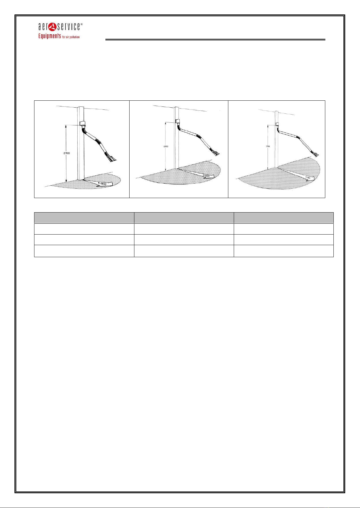
For arms with a length of 2, 3, 4 m, the table shows the range of action (corresponding to the maximum
extension of the arm), installation height, figure and diagram.
Mod.
Height of installation (m)
Radius of action (m)
ARMOTECH L = 2000
2,40
2,25
ARMOTECH L = 3000
2,40
3,25
ARMOTECH L = 4000
2,70 - 3,80
4,25

ARMOTECH
Rev 02.00
Pag. 11 di 24
©| Aerservice Equipments S.r.l. | 2021 all rights reserved è vietata la riproduzione del presente manuale, anche parziale.
ASSEMBLY OF THE ARM ARMOTECH
Par
Description
1
Assembly
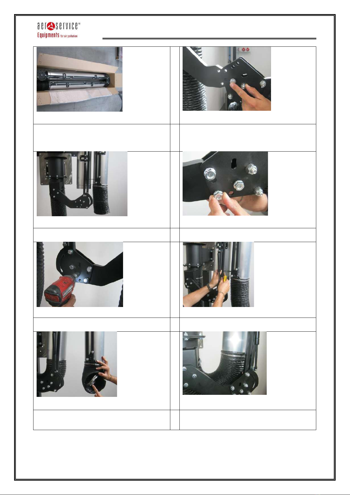
The arm is packed inside n ° 4 cardboard boxes:
1. Rotating base unit
2. Lever (for wall arm version)
3. Articulated arm assembly incl. aluminium tubes and PVC sleeves
4. Suction hood incl. bolts
1
2 –open the box with the rotating base and check
that the hardware kit, the rotating base unit, the
flexible hose and the 3 pre-assembled screws are
present.
3 –use the screws of the bag to connect the
rotating flange of the rotating base unit to the
lower flange of the wall bracket.
In this phase, lubricate the internal part of the r
rotating base unit with grease.
4 –ensure that all M8 screws are tightened fix.
5 –open the box of the lever and check that the
hardware kit and the lever are present.
6 –use the pre-assembled screws on the rotating
base unit to secure the lever on it.
Be sure to tighten all three screws.
1
4
3
2
ARMOTECH
Rev 02.00
Pag. 12 di 24
©| Aerservice Equipments S.r.l. | 2021 all rights reserved è vietata la riproduzione del presente manuale, anche parziale.
7 –open the box of the articulated arm assembly
and check its integrity.
8 –use one of the screws of kit supplied to fix the
structure to the lever.
Use the hole indicated first, to make assembly
easier.
9 –lift the structure until the remaining holes
match and insert the appropriate screws.
10 –screw the flanged nuts to the screws.
11 –be sure to tighten all three M10 screws.
12 –carefully remove the plastic band that keeps
the pantograph system closed.
13 –remove the two hose clamps from inside the
hose.
14 –use a clamp to secure the flexible sleeve to
the aluminum tube.

ARMOTECH
Rev 02.00
Pag. 13 di 24
©| Aerservice Equipments S.r.l. | 2021 all rights reserved è vietata la riproduzione del presente manuale, anche parziale.
15 –open the suction hood box and check the
integrity of the hood and the presence of the
protective band called "clamp cover".
16 -
17 –remove the screw and nut. The red bakelite
washers must remain attached to the joint
structure.
18 –insert the clamp cover into the hood
19 –screw the suction hood to the joint using the
screws removed previously, making sure to insert
the belleville washers (dished washers) in the
correct direction.
Make all the adjustments of the joint by screwing
or unscrewing the system.
20 –use the second hose clamp to fix the flexible
sleeve and finally use the clamp cover to hide
everything.
21 –move and check correct maneuverability and, if necessary, review the adjustments made previously.
ARMOTECH
Rev 02.00
Pag. 14 di 24
©| Aerservice Equipments S.r.l. | 2021 all rights reserved è vietata la riproduzione del presente manuale, anche parziale.
TYPES OF WALL BRACKET
Par
Descrption
1
Description types of wallbracket:
1) Bracket for central ventilation plants;
2) Bracket for fan;
3) Bracket with RF1 adapter.
Bracket for central ventilation plants, without hose.
ARMOTECH
Rev 02.00
Pag. 15 di 24
©| Aerservice Equipments S.r.l. | 2021 all rights reserved è vietata la riproduzione del presente manuale, anche parziale.
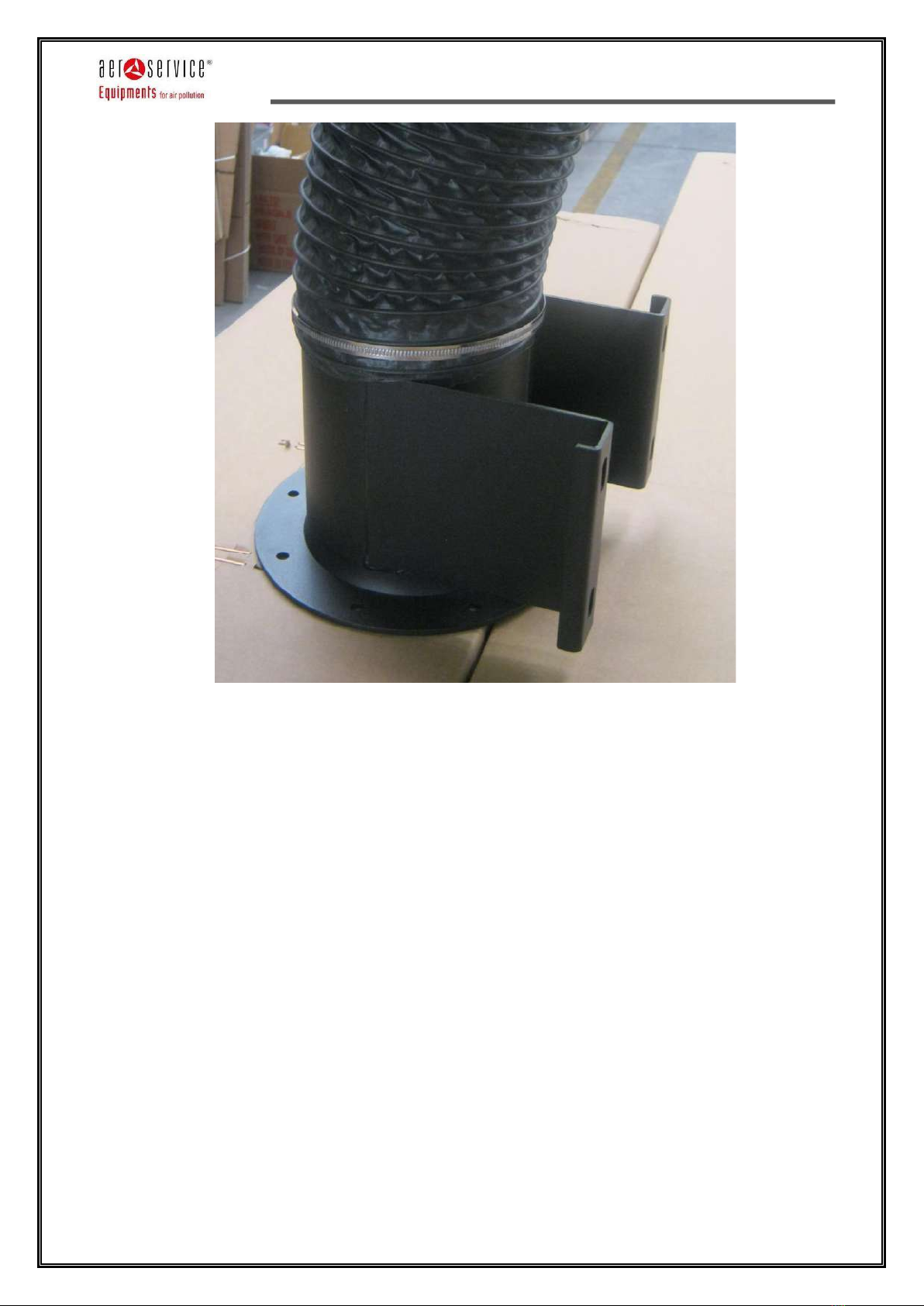
Bracket for central ventilation plants, with hose

ARMOTECH
Rev 02.00
Pag. 16 di 24
©| Aerservice Equipments S.r.l. | 2021 all rights reserved è vietata la riproduzione del presente manuale, anche parziale.
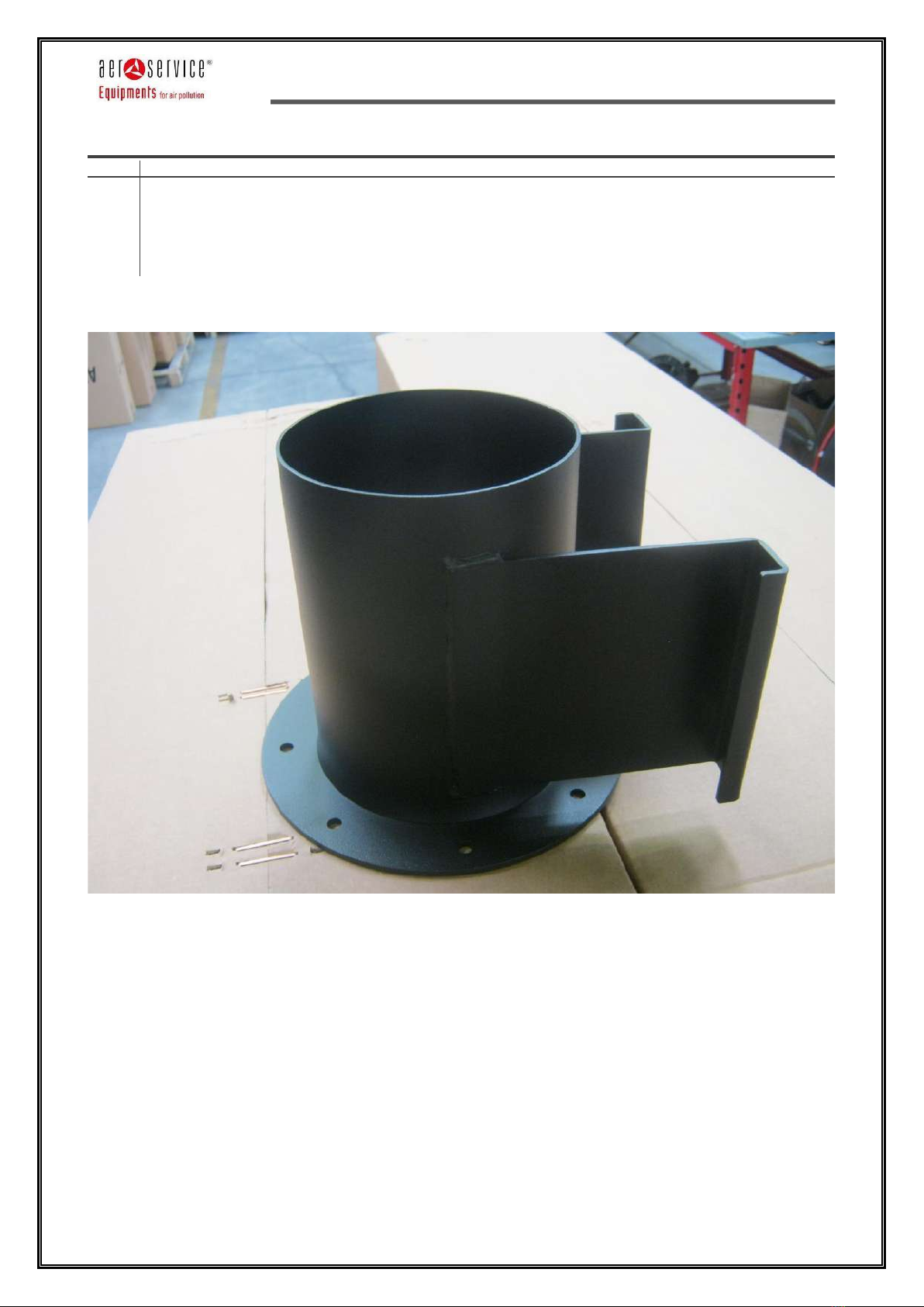
Bracket for extractor fan
FLANGE WITH HOLES FOR
FIXING OF FAN
MOD. EV 15 / EV 18
FLANGE WITH HOLES FOR
FIXING OF ROTATING
BASE UNIT OF THE
SUCTION ARM

ARMOTECH
Rev 02.00
Pag. 17 di 24
©| Aerservice Equipments S.r.l. | 2021 all rights reserved è vietata la riproduzione del presente manuale, anche parziale.
Bracket with RF1 adapter

ARMOTECH
Rev 02.00
Pag. 18 di 24
©| Aerservice Equipments S.r.l. | 2021 all rights reserved è vietata la riproduzione del presente manuale, anche parziale.
FIRST START
Par
Description
1
Recommendations
Permitted environmental conditions
-The ambient operating temperature of the machine is between -10 ° C and 60 ° C.
-The humidity of the internal environment in which the work is carried out must be between 0% and
90%.
-THE EQUIPMENT CANNOT BE USED IN AN EXPLOSIVE ATMOSPHERE!
Indications relating to the removal / elimination of waste materials
The elimination of this material must be carried out according to current regulations.
Recommendations on the prevention measures that must be adopted by the user
For the replacement operations of any damaged parts, consult the manufacturer.
Testing the machine
It is carried out by the manufacturer at its headquarters before shipment.
After carrying out the checks described above, turn on the suction arm with the switch on the panel and
adjust the position of the suction arm.

ARMOTECH
Rev 02.00
Pag. 19 di 24
©| Aerservice Equipments S.r.l. | 2021 all rights reserved è vietata la riproduzione del presente manuale, anche parziale.
FIRST START
Par
Description
2
Normal use
The equipment must only be used to suck in semi-dusty air of low and medium grain size deriving from
industrial processes through the suction arm or the flexible hose whose ends are inserted one into the
special attachment on the suction arm, the other near the position where the fumes are generated (e.g.
welding fumes).
For any other use, other than that described, the manufacturer is not liable.
Usage rules
- In general, do not disassemble or remove any part of the suction arm when it is in operation or connected
to the power supply.
- Do not insert the electric cable into the joints of the arm.
- Do not tamper with the components of the electrical panel.
- Do not operate the vacuum cleaner for a long time with the arm nozzle closed.
- Do not suck up liquids.
IMPORTANT NOTE!
THE EQUIPMENT CANNOT BE USED IN AN EXPLOSIVE ATMOSPHERE!
Most frequent faults: causes and remedies
Given that most of the malfunctions occur due to incorrect use of the system, some possible malfunctions
that may occur and the measures to be taken to remedy them are indicated in the following table.
FAULT
POSSIBLE CAUSE
REMEDY
The suction arm does not support itself,
maneuverability and positioning of the
hood is compromised.
•The clutches are loose :
• new clutches that must grip
the support material
• consumption of the same
Tighten the fixing bolts gradually and not
too much so as not to compromise
maneuverability.
The sleeves break near the grip
The clutch bolts are tightened too much,
overcoming the resistance of the joints
•Loosen the clutch bolts, and
replace the hoses:
• hood connection forearm tube
(replacement can be carried out
by the customer)
• spring part tube (must be
replaced by the manufacturer
for safety reasons)
Breakage of flexible fittings.
Wear, abrasion, puncture etc. caused by
incandescent material sucked in by the
arm.
Remove and replace the hose clamps
The fan over the suction arm stops
suddenly.
Power failure.
Restore the power supply
The fuse has blown
Replace the fuse.
The thermal switch has tripped.
Open the switchboard and reset the
switch.
Check the reasons why the thermic
tripped.
The engine burned out.
Repair where possible or replace. See
related manual.
Turn off
To turn off the arm, turn OFF the switch on the electric switch box.
ARMOTECH
Rev 02.00
Pag. 20 di 24
©| Aerservice Equipments S.r.l. | 2021 all rights reserved è vietata la riproduzione del presente manuale, anche parziale.
Description of dangers and specific protections
However, the manufacturer has taken steps to reduce the dangers that may arise due to incorrect use of the
machine by installing protective devices on the machine itself.
Description of hazards that cannot be eliminated from the security measures adopted
The dangers that cannot be eliminated from the safety measures adopted by the manufacturer are caused
by incorrect use of the machine or by a failure by the user to comply with the safety standards described in
this manual.
INSTRUCTIONS FOR EMERGENCY SITUATIONS
In case of fire, use powder fire extinguishers complying with current regulations.
Never use liquid fire extinguishers.
In case of fire, pay attention to the combustion gases (plastic system).
MAINTENANCE
Par
Description
1
Ordinary and extra-ordinary maintenance
CLEANING AND ROUTINE MAINTENANCE
Adequate cleaning is recommended for optimal operation. Regular checks and cleaning of the fan impeller
should be provided.
For normal cleaning operations, commercially available cleaners can be used.
Regular maintenance of the system increases its duration and operating safety, the hood internal joint must
be periodically greased.
EXTRAORDINARY MAINTENANCE, REPLACEMENTS AND REPAIRS
Extraordinary operations are those for the repair and replacement of one or more components of the
the system that normally becomes necessary only after years of good operation, which do not alter the
characteristics of the machine.
The device does not require any particular replacements except in cases where there is a possible filtering of
the fluid downstream of the system.
The parts most subject to wear and which need to be replaced over time can be the flexible hose, the nozzle
and the centrifugal impeller of the fan.
In the event of substantial changes, the manufacturer cannot be held responsible for any dangers that may
arise.
Table of contents
Other Aerservice Equipments Welding Accessories manuals


