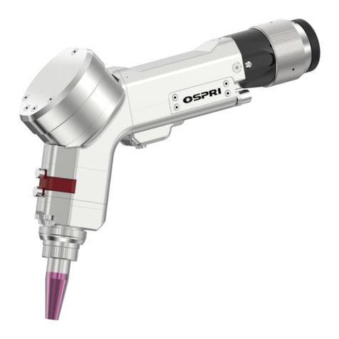
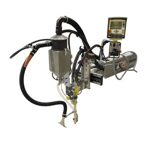
OSPRI LHSW200 User manual

LHSW200 User Manual V7.0
Product Description

CONTENTS
Chapter 1 Application Methods
Application Methods...................................................................... 01
Chapter 2 General Introduction
2.1 Product Parameter ..................................................................02
2.2 Product Feature ......................................................................02
Chapter 3 Structural Feature
3.1 Brief Description of Product Structure .....................................03
3.2 Brief Description of Product Parts ...........................................04
Chapter 4 Product Installation
5.1 Maintenance of Protection Window.........................................12
5.2 Maintenance of Collimation Lens........................................... 14
5.3 Maintenance of Focus Lens....................................................15
Chapter 5 Product Maintenance
4.1 LHSW200 Dimension Drawing................................................05
4.2 Welding Head Connection.......................................................06
4.2.1 Cooling Water Connection....................................................06
4.2.2 Gas Connection....................................................................07
4.2.3 Fixed Mount Installation for Wire Feeding…………………...08
4.2.4 Methods to Find the Focus………….......................………...08
4.3 QBH Fiber Connection......……………………………......……..09
Chapter 6 Wiring Connection
6.1 Wiring Diagram.......................................................................16
6.2 Controller Wiring Definition.....................................................16
6.3 Touch Screen Instruction........................................................18
Chapter 7 Technique Parameter
7.1 Welding Parameter Table ........................................................27

Chapter 1 Application Methods
01
Method 1:
Method 2:

2.1 Product Parameter
2.2 Product Feature
02
Chapter 2 General Introduction
Product Name Handheld Wobble Welding Head
Model LSHW200
Connector Type QBH
Wavelength 1080±10nm
Laser Power 2KW
Focus Length 125mm/150mm
Collimation Length 50mm
Nozzle M13*0.75
Wobbling Speed 0~4000mm/s
Wobbling Range 0~5mm
Gas Blowing Way Coaxial Blowing
Gas Pressure ≤1Mpa
Protection Window 20x3 mm
Net Weight 0.94KG
① User-friendly for maintenance with dual cartridges of protection windows
design,to extend service lifespan of focus lens;
② Made of high-precition industial machinery, 0.94KG in weight is portable
to carry;
③Various nozzles to meet different welding technical demands;
④ Water cooling for all optics and welding head cavity;
⑤ Capactive safety protection to avoid laser damage during handheld
operation;
⑥ Ergonomi design for comfortable operation

03
Chapter 3 Structural Feature
3.1 Brief Description of Product Structure
QBH Connector
Collimator
Protection
Window Cartidge Wobble&Focus
Part
Focus
Protection
Window
Welding
Protection
Window
Gas Blowing&Focusing
Module

04
3.2 Brief Description of Product Parts
① QBH Module: Locked connection between QBH fiber tip and handheld
welding head;
② Collimation Module: Convert the diverged beam into parallel beam;
③ Wobbling Focus Part: Focus the parallel beam into a spot and control
the wobbling trajectory of range 0~5mm;
④ Focus Protection Window Cartridge: Avoid dirts from entering onto the
focus lens, which can extend the service lifespan of focus lens;
⑤ Welding Protecion Window Cartridge: Prevent the dusts and spatters
entering the head and protect the focus lens;
⑥ Gas Blowing&Focusing Module: Adjusting focus, and blowing gas to
prevent the workpiece from being oxidized, by destroying the laser effect
on the workpiece surface of the ionosphere to form isolation the workpiece
and air.

Chapter 4 Product Installation
4.1 LHSW200 Dimension Drawing
05
For collimation length F50mm and focus length F150mm
Attention
Attention
1.Ensure standard and reliable grounding before power on;
2.Clean the QBH fiber tip carefully before connect it to the
welding head as any dirst and dust would caused optics
burned inside;
3.Clean and dust-free environment is required when
replacing protection window.
4.LHSW200 welding head is not allowed to work without
water cooling;
5.Hot plugging is forbiden;
6.Ensure the red light comes out of the nozzle before firing
the laser;

4.2 Welding Head Connection
06
4.2.1 Cooling Water Connection
Integrated design for water cooling system:
one inlet and one outlet cooling connection
Cooling Water
Hose φ6mm
Cooling Water
Hose φ6mm

4.2.2 Gas Connection
07
Attention:Gas should be filtered and dried otherwise the
protective window would be contaminated and damaged.
① Gas connector shoule be connected with φ6mm hose and input
protective gas, with suggested input flow <30L/Min, which will protect
the weld material surface and extend the lifespan of protective window.
High purity of N2 and Argon gas is suggested to process
Protective Gas
Hose φ6mm

08
Due to the different datum of every laser source,
here we introduce methods to find the focus
point:
a) Loosen the part ①, fit the tube part ② where
the smallest point of red light appears ( this
point does not coincide with the laser focus)
b) Turn off the ‘PE Protect’ in control panel and
set the laser power at 150W approximately.
Then aim the hand-held welding head at the
stainless steel sheet and, point the laser and
move the head up and down. The focus point is
where the spark is greatest;
c) To set laser power to 250W around and
operate in the same way with alumium sheet
instead of stainless steel will help find the focus
point more precisely.
4.2.3 Fixed Mount Installation for Wire Feeding
4.2.4 Methods to Find the Focus

4.3 QBH Fiber Connection
09
① Put the welding head horizontally, then take out dust-proof cover;
Note: In case the fiber head is with original dust-proof gasket, users
can choose whether install dust-proof cover or not according to actual
demand.
Dust-proof Cover
② Cover the dust-proof cover which is in the white accessory box, onto the
fiber laser tip;

10
③ Turn the QBH connector into the open state, that is, screw it to the
limit position counterclockwise (where can hear a “thud”)
④ Align the red dot on the fiber head with the red dot on the QBH
connector, and slowly insert the fiber tip into the QBH connector.
Red Dot Mark

11
⑤ Turn the QBH connector to the locked state, that is, screw it toward
the limit position clockwise (where can hear a “thud” sound). Then lift
the swivel nut up and screw the nut clockwise again until the fiber tip is
compressed tightly. (Clockwise: toward the direction of the “locked”
icon)
Note: Wrape with masking tape after plugging fiber tip.

Chapter 5 Product Maintenance
12
Loosen the two M2.5 screws and pull out
the cartridges
5.1 Maintenance of Protection Window
In case poor welding performance occurs while welding protection
window is normal, but burning points on the SKL-A (ceramic piece) the
collimator protection window or focus protection window possibly is
polluted or damaged. In this condition, please pull out the protection
window drawer to check the windows.
5.1.1 Disassembly of Welding Protection Window

13
The structure of welding protection window as shown below:
Protection Window
Clamp Ring
Protection Window
PMD20T3
O Sealing Ring
21×15×3

14
Remove the three screws in sequence as shown above, and
disassemble the collimation protection window and lens to
maintenance with lens dismantling tool. Please mind the proper
direction of collimation lens when assembling it.
④ Hold the wiping swabs with right hand to gently wipe both sides of the
lens in a single direction from bottom to top or from left to right, and blow
the lens surface with the rubber air blow to confirm that there is no foreign
matters on the cleansed lens surface.
5.2 Maintenance of Collimation Lens
5.2.1 Disassembly of Collimation Lens
5.2.2 Cleaning of Collimation Lens
① Tools:dust-free wiping swabs, isopropyl alcohol, dry and pure compressed air.
② Spray isopropyl alcohol onto the dust-free wiping swabs.
③ Gently pinch the both sides of the lens with the left thumb and index finger.
⑤ The cleansed lens must be installed into the cutting head’s body as soon
as possible or stored in other clean and sealed container.

15
Remove the two parts in sequency as shown above, and disassemble
the focus lens to maintenance with lens dismantling tool. Please mind
the proper direction of collimation lens when assembling it.
5.3 Maintenance of Focus Lens
5.3.1 Disassembly of Focus Lens
5.3.2 Cleaning of Focus Lens
① Tools:dust-free wiping swabs, isopropyl alcohol, dry and pure compressed air.
② Spray isopropyl alcohol onto the dust-free wiping swabs.
③ Gently pinch the both sides of the lens with the left thumb and index finger.
④ Hold the wiping swabs with right hand to gently wipe both sides of the
lens in a single direction from bottom to top or from left to right, and blow
the lens surface with the rubber air blow to confirm that there is no foreign
matters on the cleansed lens surface.
⑤ The cleansed lens must be installed into the cutting head’s body as
soon as possible or stored in other clean and sealed container.

16
button cable
communication
cable
wire feeder cable
Wiring Diagram
6.2 Controller Wiring Definition
PIN Defintion Description
1. DA+ analog output (control the peak power of laser source)
9. DA- analog output GND
4. PWM+ pulse width modulation (control laser output duty cycle)
13. PWM- pulse width modulation ground
3. Enable enable output signal (PNP)
11. Red Light red light output signal (PNP)
15. 24V 24V power output
8. 24V 24V power output
12. 0V 0V output
Chapter 6 Wiring Connection
6.1 Wiring Diagram
A、CN1(DB15 Female):

17
Pin Description Pin Description
1 button signal input
(connect with the yellow wire)
8 24V controller
output
2 nozzle touched signal
(connect with the grenn wire)
14 0V controller
output
3 protective gas solenoid valve output
(PNP type)
15 24 controller
output
7 0V,controller output
C、CN3(DB9 Female):
RS232 communication port-Connect to the 7-inch hand-
touched controller screen;
B、CN2(DB15 Male):
Pin Definition Description
1 DIR+ Direction +
2 DIR- Direction -
3 PUL+ Pulse +
4 PUL- Pulse -
D、CN4(DB9 Male):
Connect to the drive of wire feeder ’s motor, the pulse
equivalent of the motor is set to 1000P/R;
E、POWER (3-pins power plug)
24V: Connect to switch power supply 24V;
0V:Connect to switch power supply COM;
PE:Ground Connection
F、3-pins 15V power plug
+15V:Connect to switch power supply +15V;
0V:Connect to switch power supply COM;
-15V:Connect to switch power supply -15V

18
1. Page Options: There are four pages to switch- technique, operation,
setting and test;
2. HMI Version: It indicates current version of the HMI interface;
3. Controller Version: It indicates the current program version;
4. Technique: There are 20 groups of weldign parameters available,from
No.1~No.20 each group of parameters can be saved repectively;
6.3 Touch Screen Instruction
1
2
3
4
Table of contents
Other OSPRI Welding Accessories manuals
Popular Welding Accessories manuals by other brands
Kemppi
Kemppi PFU 210e operating manual

ROBOD
ROBOD RINO TEXTILE MAX Manual for Use, Storage and Maintenance
Clarke
Clarke Weld WSC2 User instructions
Abicor Binzel
Abicor Binzel iCAT mini ABIROB G operating instructions
Sperian
Sperian Optrel STAR quick start guide
Lincoln Electric
Lincoln Electric Innershield NR-212 datasheet
