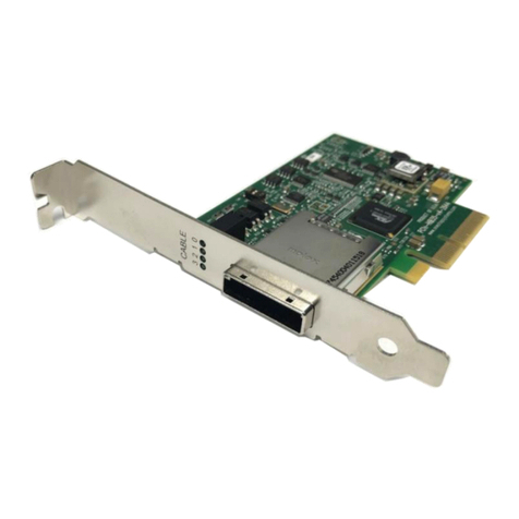
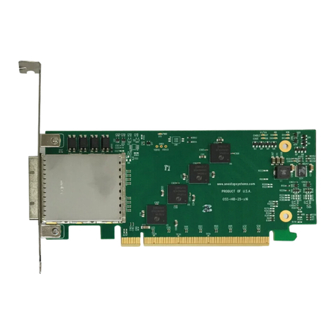
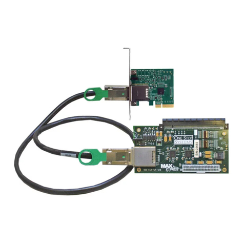
OSS OSS-PCIe-HIB25-x8 User manual

PCIe x8 Gen2 Cable Adapter
Model: OSS-PCIe-HIB25-x8
www.onestopsystems.com
Installation Guide
SKU: OSS-PCIe-HIB25-X8

One Stop Systems
OSS-PCIe-HIB25x8| 2
Table of Contents
Preface 4
Advisories 4
Safety Instructions 5
1 Introduction 7
1.1 Specifications 7
1.1 Overview 8
1.2 PCIe Card Edge x8 8
1.3 Power 8
1.4 PCIe Cable Sideband signals 8
1.5 Re-driver 9
1.6 Block Diagram & Signal Direction 9
1.7 HIB card Operating Mode 10
1.8 Connector Pin outs 11
1.9 PCI Express x16 Connector Pin out (Wired as x8) 12
2 Hardware Requirements 13
2.1 Hardware & System Requirements 13
2.1.1 HIB25-x8 card (Host and Target) 13
2.1.2 PCIe Slot & Motherboard Requirement 13
2.1.3 x16 iPass Cable 13
2.1.4 Gen3 Expansion Chassis / backplane 14
2.2 Software Requirement 14
2 Installation Procedures 15
2.1 Select Host and Target Card 15
2.2 Install HIB Host card 15
2.3 Install HIB Target card 16
2.5 Install PCIe card 17
2.6 Install link cable 17
2.7 Connect ATX Power Supply 18
2.8 Power ON the system 18
3Verify Hardware 19
3.1 LED Definition 19
3.2 LED Configuration Explanation 20
4 Software Installation 21
5 How to Get More Help 22
5.1 Contacting Technical Support 22
5.2 Returning Merchandise 22
5.3 Online Support Resources 22

One Stop Systems
OSS-PCIe-HIB25x8| 3

One Stop Systems
OSS-PCIe-HIB25x8| 4
Preface
Advisories
Five types of advisories are used throughout this manual to provide helpful information, or to alert you to the potential for hardware damage
or personal injury.
NOTE
Used to amplify or explain a comment related to procedural steps or text.
IMPORTANT
Used to indicate an important piece of information or special “tip” to help you
CAUTION
Used to indicate and prevent the following procedure or step from causing damage to the equipment.
WARNING
Used to indicate and prevent the following step from causing injury.
DANGER or STOP
Used to indicate and prevent the following step from causing serious injury or significant data loss
Disclaimer: We have attempted to identify most situations that may pose a danger, warning, or caution condition in this manual. However, the
company does not claim to have covered all situations that might require the use of a Caution, Warning, or Danger indicator.

One Stop Systems
OSS-PCIe-HIB25x8| 5
Safety Instructions
Always use caution when servicing any electrical component. Before handling the expansion chassis, read the following instructions and safety
guidelines to prevent damage to the product and to ensure your own personal safety. Refer to the “Advisories” section for advisory
conventions used in this manual, including the distinction between Danger, Warning, Caution, Important, and Note.
Always use caution when handling/operating the computer. Only qualified, experienced, authorized electronics personnel should
access the interior of the computer and expansion chassis per UL and IEC 60950-1
The power supplies produce high voltages and energy hazards, which can cause bodily harm.
Use extreme caution when installing or removing components. Refer to the installation instructions in this manual for precautions
and procedures. If you have any questions, please contact Technical Support.
WARNING
Never modify or remove the radio frequency interference shielding from your workstation or expansion unit. To do so may
cause your installation to produce emissions that could interfere with other electronic equipment in the area of your
system.
When Working Inside a Computer
1. Before taking covers off a computer, perform the following steps:
2. Turn off the computer and any peripheral devices.
3. Disconnect the computer and peripheral power cords from their AC outlets or inlets in order to prevent electric shock or system
board damage.
In addition, take note of these safety guidelines when appropriate:
To help avoid possible damage to systems boards, wait five seconds after turning off the computer before removing a component,
removing a system board, or disconnecting a peripheral device from the computer.
When you disconnect a cable, pull on its connector or on its strain-relief loop, not on the cable itself. Some cables have a connector
with locking tabs. If you are disconnecting this type of cable, press in on the locking tabs before disconnecting the cable. As you pull
connectors apart, keep them evenly aligned to avoid bending any connector pins. Also, before connecting a cable, make sure both
connectors are correctly oriented and aligned.
CAUTION
Do not attempt to service the system yourself except as explained in this manual. Follow installation
instructions closely.

One Stop Systems
OSS-PCIe-HIB25x8| 6
Protecting Against Electrostatic Discharge
Electrostatic Discharge (ESD) Warning
Electrostatic Discharge (ESD) is the enemy of semiconductor devices. You should always take precautions to eliminate any
electrostatic charge from your body and clothing before touching any semiconductor device or card by using an
electrostatic wrist strap and/or rubber mat.
Static electricity can harm system boards. Perform service at an ESD workstation and follow proper ESD procedures to reduce the risk of
damage to components. We strongly encourage you to follow proper ESD procedures, which can include wrist straps and smocks, when
servicing equipment.
You can also take the following steps to prevent damage from electrostatic discharge (ESD):
When unpacking a static-sensitive component from its shipping carton, do not remove the component’s anti-static packaging
material until you are ready to install the component in a computer. Just before unwrapping the anti-static packaging, be sure you
are at an ESD workstation or are grounded.
When transporting a sensitive component, first place it in an anti-static container or packaging.
Handle all sensitive components at an ESD workstation. If possible, use anti-static floor pads and workbench pads.
Handle components and boards with care. Do not touch the components or contacts on a board. Hold a board by its edges or by its
metal mounting bracket.

One Stop Systems
OSS-PCIe-HIB25x8| 7
1 Introduction
PCIe x8 Gen2 Host Cable Adapter install easily into a computer's PCIe slot. A PCIe cable can then be plugged into the adapter to extend the PCIe
bus from the motherboard to an external device, like an expansion enclosure or storage device. The PCIe x8 adapter extends the PCIe bus at
40Gb/s with extremely low latency because there is no conversion software
Part numbers:
OSS-PCIE-HIB25-x8-T (Target)
OSS-PCIE-HIB25-x8-H (Host)
1.1 Specifications
Item
Description
Form Factor
PCIe x8 half-height, half-length
Dimensions
4.5 x 2.7 inches
Bandwidth / Backplane
Interface
PCIe x8 Gen2
Power Consumption
4W
Connector
PCIe x8 Cable connector
PCIe x8 Edge connector
Re-drivers
5.0 Gbps 4-lane PCIe Gen2 Re-driver
Pericom, pat number P12EQX5804
Bracket
Standard and low profile brackets available
No LEDs on the bracket
Operating Temperature
0˚C to +70˚C environment
Operating Humidity
10% to 90% relative humidity non-condensing
Storage Humidity
5% to 95% relative humidity non-condensing
Industry Specifications
PCIe External Cabling Specification, Rev. 1.0
PCI Express™ Card Electromechanical
Specification, Rev. 3.0
PCI Express ® Base Specification, Rev. 3.0
ATX Specification, Version 2.2
Agency Compliance
• FCC Class A
• CE
• RoHS
Operating System
Windows 10, Windows Server 2012 R2; Linux OS based

One Stop Systems
OSS-PCIe-HIB25x8| 8
1.1 Overview
1.2 PCIe Card Edge x8
The PCIe Card edge will be directly routed x8 interface to the Pericom Chip
In host mode, the add-in card will accept a clock as an input.
In target mode, the add-in card will drive a clock. It will also provide a reset output and a PS_ON# signal.
1.3 Power
Power is provided by the PCI-e card slot.
Power required by internal components of OSS-PCIe-HIB-25-x16 is estimated to be 4 watts when both ports are fully linked and
operating in Gen2 mode.
Cable power is to be provided per PCIe cable specification. When an active cable (powered transceiver) is used, additional power is
required from the PCI-e card slot.
Power will be supplied +3.3V, +3.3Vaux through Card Edge.
Some power rails will be derived from the onboard circuitry.
1.4 PCIe Cable Sideband signals
All Cable sideband signals CPERST#, CPWRON, CPRSNT#, CWAKE# to be connected per the PCIe Cable specification.
Additional isolation of signal CE_PWRON# (card edge power control) shall be provided by a physical switch.
This switch allows user to electrically isolate this signal from the card edge connector.

One Stop Systems
OSS-PCIe-HIB25x8| 9
1.5 Re-driver
The board uses the Pericom chip to link from Card Edge to Cable Connector.
The HIB card interface includes the following features
oOne x8 PCIe bus routed to PCIe Card Edge
oOne x8 PCIe bus routed to the PCIe Cable Connector
oPCIe Clock route from Card Edge to Cable Connector via a Clock Buffer.
1.6 Block Diagram & Signal Direction

One Stop Systems
OSS-PCIe-HIB25x8| 10
1.7 HIB card Operating Mode
Use cases for all operating modes.
1. Mode 1: Target Mode: In this mode, the card is populated with three thermocouples. The card is set to operate in Target mode and
it is plugged into expansion backplane Upstream slot.
2. Mode 2: Host Mode. In this mode, the card is not populated with thermocouples. The card is set to operate in Host mode and it is
plugged into computer’s motherboard PCIe slot.

One Stop Systems
OSS-PCIe-HIB25x8| 11
1.8 Connector Pin outs
PCI Express x8 Cable Connector
Row A
Row B
Row A
Row B
Pin #
Signal Name
Signal
Name
Pin #
Signal
Name
Signal Name
1
GND
GND
13
GND
GND
2
PETp0
PERp0
14
CREFCLK+
PWR (3.3V)
3
PETn0
PERn0
15
CREFCLK-
PWR (3.3V)
4
GND
GND
16
GND
PWR (3.3V)
5
PETp1
PERp1
17
RSVD
PWR RTN
6
PETn1
PERn1
18
RSVD
PWR RTN
7
GND
GND
19
SB_RTN
PWR RTN
8
PETp2
PERp2
20
CPSRNT$#
CWAKE#
9
PETn2
PERn2
21
CPWRON
CPERST#
10
GND
GND
22
GND
GND
11
PETp3
PERp3
23
PETp4
PETp4
12
PETn3
PERn3
24
PETn4
PERp4

One Stop Systems
OSS-PCIe-HIB25x8| 12
1.9 PCI Express x16 Connector Pin out (Wired as x8)
PIN#
NAME
PIN#
NAME
B1
+12V
A1
PRSNT1#
Mechanical Key
B2
+12V
A2
+12V
B3
+12V
A3
+12V
B4
GND
A4
GND
B5
SMCLK
A5
TCK
B6
SMDAT
A6
TDI
B7
GND
A7
TDO
B8
+3.3V
A8
TMS
B9
TRST#
A9
+3.3V
B10
3.3Vaux
A10
+3.3V
B11
WAKE#
A11
PERST#
B12
RSVD
A12
GND
End of the x1 connector
B13
GND
A13
REFCLK+
B14
PETp0
A14
REFCLK-
B15
PETn0
A15
GND
B16
GND
A16
PERp0
B17
PRSNT2#
A17
PERn0
B18
GND
A18
GND
B19
PETp1
A19
RSVD
End of the x4 connector
B20
PETn1
A20
GND
B21
GND
A21
PERp1
B22
GND
A22
PERn1
B23
PETp2
A23
GND
B24
PETn2
A24
GND
B25
GND
A25
PERp2
B26
GND
A26
PERn2
B27
PETp3
A27
GND
B28
PETn3
A28
GND
B29
GND
A29
PERp3
B30
RSVD
A30
PERn3
B31
PRSNT2#
A31
GND
B32
GND
A32
RSVD
B33
PETp4
A33
RSVD
End of x8 connector
B34
PETn4
A34
GND
B35
GND
A35
PERp4
B36
GND
A36
PERn4
B37
PETp5
A37
GND
B38
PETn5
A38
GND
B39
GND
A39
PERp5
B40
GND
A40
PERn5
B41
PETp6
A41
GND
B42
PETn6
A42
GND
B43
GND
A43
PERp6
B44
GND
A44
PERn6
B45
PETp7
A45
GND
B46
PETn7
A46
GND
B47
GND
A47
PERp7
B48
PRSNT2#
A48
PERn7
B49
GND
A49
GND
NC = NOT CONNECTED

One Stop Systems
OSS-PCIe-HIB25x8| 13
2Hardware Requirements
The following steps will guide you through the installation of your HIB25-x8 Host and Target card.
2.1 Hardware & System Requirements
1. Computer / Server motherboard with x8 Gen2 PCIe slot
2. HIB25-x8-H, qty 1: Host card
3. HIB25-X8-T, qty 1: Target card
NOTE: The HIB25-x8 card works in pair (one as host card and other as target card)
4. One x8 iPass cable
5. OSS Expansion chassis with Gen2 backplane, or OSS expansion backplane and power supply.
2.1.1 HIB25-x8 card (Host and Target)
2.1.2 PCIe Slot & Motherboard Requirement
For Host Adapter card: Use a server-computer type motherboard that has a Gen3 or Gen2 x16 PCIe slot in order for the card to operate to its
max performance. The Host adapter card is recommended to be installed in a x16 connector.
2.1.3 x16 iPass Cable
Use x16 iPass cable for connecting host card and target card

One Stop Systems
OSS-PCIe-HIB25x8| 14
2.1.4 Gen3 Expansion Chassis / backplane
You need an expansion chassis with Gen2 or Gen3 backplane . Photos below are example of Gen3 OSS backplanes and an expansion unit.
The HIB card has custom pin out that unique to OSS and only OSS Target adapters will work in the upstream slot of our
expansion backplanes.
2.2 Software Requirement
1. Computer running Windows 7, 8, 10 and or Server
2. No driver is needed for the OSS-HIB25-x8

One Stop Systems
OSS-PCIe-HIB25x8| 15
2Installation Procedures
2.1 Select Host and Target Card
Select the appropriate card to use, makes sure you have the correct host and target cards. Below are photos to help you
identify between Target and Host card.
2.2 Install HIB Host card
Power down the host computer first before installing the host card. Do not install the host card while the computer is ON.
Install the HIB25-X8 host card into the available PCIe slot in the computer motherboard. Use a x8 or x16 Gen2/Gen3 PCIe slot.
Secure the card

One Stop Systems
OSS-PCIe-HIB25x8| 16
2.3 Install HIB Target card
Do not plug in the target card while expansion unit or the expansion backplane is ON as this can damage the board. Turn OFF
the unit first before installing the card.
The HIB Target card will only work in the OSS backplane designated “Upstream”slot. It will not function in the downstream
slot or the end-point slot of the backplane.
Install the Target card in the OSS expansion backplane. Plug-in the target card in the designated Upstream slot of the backplane.
Photos below are different backplanes showing where the location of the Upstream slot.

One Stop Systems
OSS-PCIe-HIB25x8| 17
2.5 Install PCIe card
Plug-in your 3rd party PCIe card in the expansion backplane. Use the downstream slot of the OSS backplane. See photos below.
2.6 Install link cable
Connect the PCIe iPass x8 cable between the host and target cards. Plug in the cable to the host card.
Plug in the other end of the cable to the target card. Make sure the cable is firmly latched in to the cable connectors of the card.
Photo below is a block diagram of an OSS expansion unit linked to a host server / computer.

One Stop Systems
OSS-PCIe-HIB25x8| 18
2.7 Connect ATX Power Supply
If you are using an expansion chassis, the power supply is already part of the unit. You can skip this step.
If you are using an expansion backplane, plug-in the ATX power supply cable into the 24pin ATX power connector on the OSS board
Connect power to the PSU and turn the switch to ON position.
2.8 Power ON the system
Turn On the main power of the host computer.
Start the computer by pushing the power button.
Upon powering ON the Host system, it will send a sideband signal to the Target card triggering the target expansion system to turn
ON.
If the expansion unit or the HIB card are not powering ON, check the link cable make sure it is firmly connected. The target and
host card must be fully seated in the PCIe slot in order to work correctly.

One Stop Systems
OSS-PCIe-HIB25x8| 19
3 Verify Hardware
A operational host and target cards will have the following LEDs on the board illuminated.
1. PWR LED
2. x4 CBL and EDGE LEDs
3. x8 CBL and EDGE LEDs
3.1 LED Definition
PWR –Board has power
CBL –Signal detect on cable*
EDGE –Signal detect on card edge*
*Signal detect does not mean it has a link, but rather it identifies there is a signal on the card edge. If the link does not appear to be stable, it
could mean that there is a compliance pattern being generated by the PCIe device interfacing with this card.
If the board is operating on x4 mode, x4 CBL and EDGE are illuminated. This is indicative of a x4 slot PCIe slot (electrical) where the host or
target card is installed.

One Stop Systems
OSS-PCIe-HIB25x8| 20
3.2 LED Configuration Explanation
D17
D19
D18
D20
Indication
0
0
0
0
No valid signal from root or endpoint
0
0
0
1
NA
0
0
1
0
Root is sending valid training signals on either lane 0 only (x1) or lanes 0-3 (x4) to the
target; no valid signal coming from endpoint.
0
0
1
1
Root is x8 and is sending valid training signals on lanes 0-7 to the root; no valid signal
coming from endpoint.
0
1
0
0
NA
0
1
0
1
NA
0
1
1
0
NA
0
1
1
1
NA
1
0
0
0
Endpoint is sending valid training signals on either lane 0 only (x1) or lanes 0-3 (x4) to the
root; no valid signal coming from root.
1
0
0
1
NA
1
0
1
0
Valid signal levels from both root and endpoint on either lane 0 only (x1) or lanes 0-3 (x4)
1
0
1
1
Endpoint is sending valid signals on either lane 0 only (x1) or lanes 0-3 (x4) to the root,
but root is sending valid signals on lanes 0-7 (x8) (root and endpoint can’t agree on lane
width)
1
1
0
0
NA
1
1
0
1
NA
1
1
1
0
Root is sending valid signals on either lane 0 only (x1) or lanes 0-3 (x4) to the endpoint,
but endpoint is sending valid signals on lanes 0-7 (x8) (root and endpoint can’t agree on
lane width)
1
1
1
1
Valid signal levels from both root and endpoint on lanes 0-7 (x8)
Table of contents
Other OSS PCI Card manuals
