OSS OSS-EOS-2U-41 User manual

User Manual
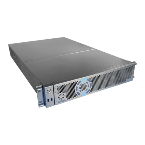
2U EOS Server
Expansion Optimized Server
SKU: OSS-EOS-2U-41
www.onestopsystems.com

One Stop Systems
OSS-EOS-2U-4I | 2
Table of Contents
Preface.................................................................................................................................................................................... 4
Advisories ............................................................................................................................................................................................................4
Safety Instructions ...............................................................................................................................................................................................5
Protecting Against Electrostatic Discharge ..........................................................................................................................................................6
1 Introduction...................................................................................................................................................................... 7
1.1 General Specifications...............................................................................................................................................................................7
1.2 Overview...................................................................................................................................................................................................9
1.3 Motherboard Layout...............................................................................................................................................................................11
1.4 Quick Reference......................................................................................................................................................................................12
1.5 Quick Reference Table ............................................................................................................................................................................ 13
1.6 Motherboard Features............................................................................................................................................................................15
1.7 Pre-Installation Information....................................................................................................................................................................16
1.8 Tools Required for Installation................................................................................................................................................................16
2 Set-up / Installation .........................................................................................................................................................17
2.1 Installation-Procedures Overview ........................................................................................................................................................... 17
2.2 Remove Top Cover ..................................................................................................................................................................................18
2.3 Check Storage & USB 3.0 Cables................................................................................................................................................................19
2.4 Remove faceplate....................................................................................................................................................................................20
2.5 Remove Drive Tray ..................................................................................................................................................................................20
2.6 Install Storage Drive .................................................................................................................................................................................21
2.7 Connect Input and Output devices...........................................................................................................................................................22
2.8 Power ON the system...............................................................................................................................................................................23
2.9 Configure BIOS .........................................................................................................................................................................................24
2.10 Install Operating System.........................................................................................................................................................................27
3OSS Target Card Installation..........................................................................................................................................28
4Attach OSS Expansion Unit............................................................................................................................................30
4.1 Connect LINK Cables.................................................................................................................................................................................30
4.2 Power Up..................................................................................................................................................................................................31
4M.2 NVME Installation ..................................................................................................................................................32
5How to Remove Power Supply ......................................................................................................................................35
6How to Remove PSU Housing........................................................................................................................................36
7How to Remove the Fan................................................................................................................................................38
8How to Install the Fan ...................................................................................................................................................39
10 BMC ..............................................................................................................................................................................41

One Stop Systems
OSS-EOS-2U-4I | 3
11 Contacting Technical Support ........................................................................................................................................43
12 Returning Merchandise to One Stop Systems ................................................................................................................43
13 APPENDIX A Compliance..............................................................................................................................................44
FCC ...............................................................................................................................................................................................................44
CE .................................................................................................................................................................................................................44

One Stop Systems
OSS-EOS-2U-4I | 4
Preface
Advisories
Five types of advisories are used throughout this manual to provide helpful information, or to alert you to the potential for hardware damage
or personal injury.
Disclaimer: We have attempted to identify most situations that may pose a danger, warning, or caution condition in this manual. However, One
Stop Systems does not claim to have covered all situations that might require the use of a Caution, Warning, or Danger indicator.

One Stop Systems
OSS-EOS-2U-4I | 5
Safety Instructions
Always use caution when servicing any electrical component. Before handling the One Stop Systems Expansion chassis, read the following
instructions and safety guidelines to prevent damage to the product and to ensure your own personal safety. Refer to the “Advisories” section
for advisory conventions used in this manual, including the distinction between Danger, Warning, Caution, Important, and Note.
Always use caution when handling/operating the computer. Only qualified, experienced, authorized electronics personnel should access the
interior of the computer and expansion chassis.
WARNING
Never modify or remove the radio frequency interference shielding from your workstation or expansion unit. To do so
may cause your installation to produce emissions that could interfere with other electronic equipment in the area of
your system.
When Working Inside a Computer
Before taking covers off a computer, perform the following steps:
Turn off the computer and any peripheral devices.
Disconnect the computer and peripheral power cords from their AC outlets or inlets in order to prevent electric shock or system board damage.
In addition, take note of these safety guidelines when appropriate:
To help avoid possible damage to systems boards, wait five seconds after turning off the computer before removing a component,
removing a system board, or disconnecting a peripheral device from the computer.
When you disconnect a cable, pull on its connector or on its strain-relief loop, not on the cable itself. Some cables have a connector
with locking tabs. If you are disconnecting this type of cable, press in on the locking tabs before disconnecting the cable. As you pull
connectors apart, keep them evenly aligned to avoid bending any connector pins. Also, before connecting a cable, make sure both
connectors are correctly oriented and aligned.
CAUTION
Do not attempt to service the system yourself except as explained in this manual. Follow installation instructions
closely.

One Stop Systems
OSS-EOS-2U-4I | 6
Protecting Against Electrostatic Discharge
Electrostatic Discharge (ESD) Warning
Electrostatic Discharge (ESD) is the enemy of semiconductor devices. You should always take precautions to eliminate
any electrostatic charge from your body and clothing before touching any semiconductor device or card by using an
electrostatic wrist strap and/or rubber mat.
Static electricity can harm system boards. Perform service at an ESD workstation and follow proper ESD procedures to reduce the risk of
damage to components. One Stop Systems strongly encourages you to follow proper ESD procedures, which can include wrist straps and
smocks, when servicing equipment.
You can also take the following steps to prevent damage from electrostatic discharge (ESD):
When unpacking a static-sensitive component from its shipping carton, do not remove the component’s anti-static packaging material until you
are ready to install the component in a computer. Just before unwrapping the anti-static packaging, be sure you are at an ESD workstation or
are grounded.
When transporting a sensitive component, first place it in an anti-static container or packaging.
Handle all sensitive components at an ESD workstation. If possible, use anti-static floor pads and workbench pads.
Handle components and boards with care. Do not touch the components or contacts on a board. Hold a board by its edges or by its metal
mounting bracket.

One Stop Systems
OSS-EOS-2U-4I | 7
1Introduction
1.1 General Specifications
The 2U EOS server revolutionizes the capabilities of homogenous systems containing tightly coupled processors, NVMe solid-state storage,
high-speed networking, and accelerator co-processing elements such as GP-GPUs and FPGAs. The 2U EOS contains two of the newest Intel
Scalable Processors and provides the widest BIOS compatibility with dense storage and accelerator expansion systems. This allows the highly
integrated server to stand alone or form the core CPU and memory resources for a scale-out, rack level, expandable solution. The EOS server
features two storage and I/O configurations providing up to six PCIe 3.0 x16 half-height slots or 24 U.2 NVMe drives. The server supports up to
4TB of memory and a resource expanded BIOS for scale-out device enumeration and large memory mapped I/O used for GP-GPUs and
accelerators
Item
Description
Dimensions
3.45” H x 17.2” (19” with rack ears) W x 28” D (8.7 x 43.7 x 71 cm)
CPU
Dual Intel® Xeon® Scalable Processors up to 205W TDP and 28 cores
LGA 3647 socket P with 3 UPI chip-to-chip bus up to 10.7GT/s
System Memory
16x 288-pin DDR4 DIMM sockets
Up to 4TB DDR4-2933MHz 3DS ECC RDIMM or LRDIMM, 1.2V low profile
2933/2666/2400/2133MHz Frequencies in 64GB, 128GB and 256GB capacities each module
Up to 2TB Intel® Optane™ DC Persistent Memory in memory mode (Cascade Lake only)
Expansion Slots
EOS configuration:
• 4 x PCIe 3.0 x16 HH/FL Double Width slots
• 2 x PCIe 3.0 x16 HH/HL Single Width slots
• 1 x PCIe 3.0 x4 HH/HL slot with x8 physical connector
• 1x PCIe3.0 x4 M.2 slot for 2280 and 22110 M-Key modules
NVMe configuration:
2 x PCIe 3.0 x16 FH/HL Single Width slots
2 x PCIe 3.0 x16 HH/HL Single Width slots
1 x PCIe 3.0 x4 HH/HL slot with x8 physical connector
1x PCIe3.0 x4 M.2 slot for 2280 and 22110 M-Key modules
Storage Subsystem
EOS configuration:
24x hot-swap configurable SATA-3, SAS-3 or NVMe x4 2.5” x 15mm drive carriers
12Gb SAS-3 or 6Gb SATA-3 SFF-8680 slots via 3x SFF-8643 backplane connectors
NVMe x4 32Gb slots via 24x Oculink connectors
Up to 10 SATA-3 slots use no PCIe slots
12x and 24x SAS-3 slots require 1 and 2 PCIe x16 HHHL slots respectively
8x and 16x NVMe x2 slots require 1 and 2 x16 PCIe HHHL slots respectively (for 24x NVMe x4 use NVMe config)
Further expansion up to 4PB possible using OSS JBOF expansion systems
1x M.2 x4 and 2x SATA-DOM internal drive connections
NVMe configuration
24x hot-swap NVMe x4 2.5” x 15mm drive carriers
Up to 10 NVMe drive bays can be SATA-3 configured
-1x M.2 x4 and 2x SATA-DOM internal drive connections
On-board devices
Intel® C621 Express chipset
ASPEED AST2500BMC IPMI support for IPMI 2.0 with virtual medial over LAN and KVM-over-LAN support
Network Controllers
2x Intel X550 10Gigabit Ethernet each with an RJ-45
Additional 25, 40 and 100Gb Ethernet, 100Gb Infiniband or 32Gb Fiber Channel interfaces available

One Stop Systems
OSS-EOS-2U-4I | 8
USB
5 USB 3.0 with 2 on rear panel, 2 on front panel and 1 Type A internal
4 USB 2.0 with 2 on rear panel and 2 internal headers
Input/Output
7.1HD Audio Header, 1 VGA port, 2 COM ports (1 rear and 1internal header
2 Disk-on-Module ports
1 Trusted Platform Management TPM 1.2 20-pin header
BIOS
128 Mb SPI flash EEPROM with AMI BIOS
Supports PnP, PCI 3.0, ACPI 1.0-4.0, USB keyboard support, UEFI 2.3.1,
1TB BAR1 max size and 256 PCI bus enumeration support
Cooling Fans
Four 80mm x 38mm PWM hot-swap Cooling fans
Chassis
Rugged steel enclosure
Liquid paint with customizable front bezel
Weight
33-48lbs (15-22 kg)
Power Supply
1000W 100-240VAC, 47-63Hz Input:
1+1 Redundant 80plus Silver efficiency with Active PFC, PM Bus and Over Voltage Protection
15A input current at 115VAC and 7.5A at 230VAC each module
15A @ 115VAC and 30A @ 230VAC max inrush current each module
EPS 12V Output type with 22A at+5V, 83A at +12V, 0.5A at -12V, 22A at+3.3V and 3A at +5V Standby
Environment
Operating:
5°C to 35°C (41°F to 95°F) at 0 to 915m (3,000ft) altitude
5% to 90% non-condensing relative humidity, max dew point 21°C, max rate of change 5°C/hr
Non-Operating:
-20C to 60°C (-40°F to 140°F)
5% to 90% non-condensing relative humidity, max dew point 27°C, max rate of change 5°C/hr
Agency
Tested to conform to the following standards:
FCC - Verified to comply with Part 15 of the FCC Rules, Class A
Canada ICES-003, issue 4, Class A
CE Mark (EN55022 Class A, EN55024, EN61000-3-2, EN61000-3-3)
CISPR 22, Class A
Designed to conform to the following extended standards:
NOM-019
Argentina IEC60950-1
Japan VCCI, Class A
Australia/New Zealand AS/NZS CISPR 22, Class A
China CCC (GB4943), GB9254 Class A, GB17625.1
Taiwan BSMI CNS13438, Class A; CNS14336-1
Korea KN22, Class A; KN24
Russia/GOST ME01, IEC-60950-1, GOST R 51318.22, GOST R 51318.24, GOST R 51317.3.2,
GOST R 51317.3.3
TUV-GS (EN60950-1 /IEC60950-1,EK1-ITB2000)
Compliance
RoHS Compliant WEEE

One Stop Systems
OSS-EOS-2U-4I | 9
1.2 Overview

One Stop Systems
OSS-EOS-2U-4I | 10

One Stop Systems
OSS-EOS-2U-4I | 11
1.3 Motherboard Layout

One Stop Systems
OSS-EOS-2U-4I | 12
1.4 Quick Reference

One Stop Systems
OSS-EOS-2U-4I | 13
1.5 Quick Reference Table

One Stop Systems
OSS-EOS-2U-4I | 14

One Stop Systems
OSS-EOS-2U-4I | 15
1.6 Motherboard Features
CPU
Supports two 3rd Gen. Intel Xeon Scalable Processors (in Socket P+ LGA 4189) with up to 38 cores per CPU and a
thermal design power (TDP) of up to 270W
Memory
Supports up to 4 TB of 3DS LRDIMM/LRDIMM/3DS RDIMM/RDIMM DDR4 (288-pin) ECC memory with speeds of
3200/2933/2666 MHz in 16 memory slots and up to 4 TB of Intel Optane PMem 200 Series with speeds of up to 3200
MHz Note 1: The Intel Optane Persistent Memory (PMem) 200 Series are supported by the 3rd Gen. Intel Xeon
Scalable (83xx/63xx/53xx/4314) series processors. Note 2: Memory speed and capacity support depends on the
processors used in the system.
DIMM Size
Up to 256 GB at 1.2V Note: For the latest CPU/memory updates, please refer to our website at
http://www.supermicro.com/products/ motherboard
Chipset
Intel PCH C621A
Expansion Slots
• One PCIe 4.0 x8 slot (CPU2 Slot11)
• Six PCIe 4.0 x16 slots (CPU1 Slot2 / CPU1 Slot4 / CPU1 Slot9 / CPU2 Slot6 / CPU2 Slot8 / CPU2 Slot10)
• Two PCIe 4.0 x4 M.2 slots (supports M-Key 2242, 2260, 2280, and 22110)
• Two PCIe 4.0 x8 SlimSAS ports w/support of two connections each port (P1_NVME0/1, P1_NVME2/3)
Network
• Two 10G Ethernet LAN ports supported by Intel X550 LAN controller
•One Dedicated BMC LAN located on the rear I/O panel (via AST2600 BMC)
Baseboard
Management
Controller (BMC)
ASPEED AST2600 BMC
Graphics
Graphics controller & VGA support via ASPEED AST2600 BMC
I/O Devices
Serial (COM) Port
• One (serial port on the rear I/O panel (COM1)
• One front accessible serial port header (COM2)
SATA 3.0
• Eight I-SATA 3.0 ports at 6 Gb/s (I-SATA0~3, I-SATA4~7)
• Two Intel PCH powered S-SATA 3.0 Ports with support for
SuperDOM (Disk on Module) devices (S-SATA4, S-SATA5)
Video (VGA) Connections
• One VGA port on the rear I/O panel (VGA2)
• One VGA header on the motherboard for front access (VGA1
Peripheral Devices
• Four USB 3.0 ports on the rear I/O panel (USB2/3, USB4/5)
• One front-accessible USB header with support for two USB 2.0 ports (USB0/1)
• One front-accessible USB header with support for two USB 3.0 ports (USB6/7)
• One internal USB 3.0 Type-A header (USB8)
BIOS
• AMI BIOS
• ACPI 3.0 or later, PCI firmware 4.0 support, BIOS rescue hot-key, SPI dual/quad speed support, RTC (Real Time
Clock) wakeup, and SMBIOS 3.0 or later
Power
Management
• ACPI power management
• Power button override mechanism
• Power-on mode for AC power recovery
• Wake-on-LAN
• Power supply monitoring
System Health
Monitoring
• Onboard voltage monitoring for +/-12V, +5V/+5V standby, +3.3V, and +3.3V standby
• Onboard temperature monitoring for CPU, VRM, LAN, PCH, system, and memory
• 7+1 CPU switch phase voltage regulator
• CPU thermal trip support
• Platform Environment Control Interface (PECI)
Fan Control
• Fan status monitoring via BMC connections
• Single cooling zone
• Low-noise fan speed control
• Ten 4-pin fan headers
LED Indicators
• Power LED
• UID/remote UID
• LAN activity LED
• BMC Heartbeat LED
Dimensions
15.12" (W) x 13.2" (L) ATX (384.05 mm x 335.28 mm)

One Stop Systems
OSS-EOS-2U-4I | 16
1.7 Pre-Installation Information
Before using the One Stop Systems expansion chassis, you should perform the following steps:
•Inventory the shipping carton contents for all of the required parts
•Gather all of the necessary tools required for installation
•Read this manual
1.8 Tools Required for Installation
To complete the installation of the product you will need a Phillips-head screwdriver and ESD wrist strap to prevent electrostatic discharge.

One Stop Systems
OSS-EOS-2U-4I | 17
2 Set-up / Installation
CAUTION
Hardware installation shall be performed only by qualified service personnel per UL and IEC 60950-1.
Electrostatic Discharge (ESD) Warning
All PCI cards are susceptible to electrostatic discharge. When moving PCI cards, it is best to carry the cards in anti-static
packaging. If you need to set a PCIe card down, be sure to place it inside or on top of an anti-static surface. For more
information, see “Protecting Against Electrostatic Discharge” in the Preface.
WARNING
High voltages are present inside the expansion chassis when the unit’s power cord is plugged into an electrical outlet.
Disconnect the power cord from the AC outlet before removing the enclosure cover. Turning the system power off at
the power on/off switch does not remove power to components. High voltage is still present.
CAUTION
Before touching anything inside the enclosure, move to an ESD station and follow proper ESD procedures. Failure to do
so may result in electrostatic discharge, damaging the computer or its components. For more information, see
“Protecting Against Electrostatic Discharge” in the Preface.
2.1 Installation-Procedures Overview
Steps on how to setup and use the EOS system. You will find instructions for the following procedures:
1. Remove the top cover.
a. Check inside the unit for loose components or damaged parts.
2. Check SlimSas and USB cables
a. Make sure cables are firmly installed and secured
3. Remove front Bezel
4. Install NVME or M.2 Storage devices
a. Mount your choice of NVME or M.2 storage devices
5. Plug in external IO devices and power cables
6. Power UP System & Configure BIOS
7. Load or install Operating System
8. Connect OSS Expansion system

One Stop Systems
OSS-EOS-2U-4I | 18
2.2 Remove Top Cover
Remove the screw located on each side of the panel, see photo below.
Remove the screw located on the top-end of the cover, see photo below
Lift the front top cover up and slowly slide it out.

One Stop Systems
OSS-EOS-2U-4I | 19
After removing the front top cover, remove the back-end top cover. Stand right behind the unit, using both hands push the cover and then lift it
up.
2.3 Check Storage & USB 3.0 Cables
Check the “SlimSAS 8-Lane to OCulink 4-Lane x2 cables” are rigidly attached to the ports on the motherboard.
Check the other end of the cable (Oculink) is connected to the storage carrier interface board, see photos below.

One Stop Systems
OSS-EOS-2U-4I | 20
Check the USB 3.0 cable is attached to the USB3.0 port on the motherboard.
2.4 Remove faceplate
Carefully remove the front faceplate or the front bezel.
•Hold the front face plate on the right-side (as shown from the photos below) and gently pull it to detach.
2.5 Remove Drive Tray
Locate the locking tab, slide it to the left to unlock.
Pull the drive tray out from the unit by pressing the release button. The drive tray handle will extend.
Table of contents
Other OSS Server manuals
