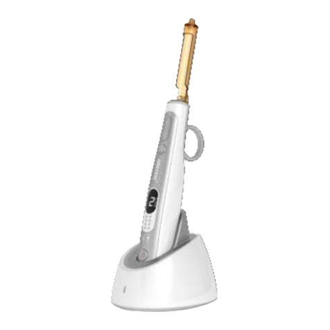
Osstem Implant K3 User manual

K3 Unit Chair Installation
Osstem Implant
Technical Support Division

K3 Unit Chair Installation
(Mechanical)
Osstem Implant

3
*Contents
ⅠK3 installation Checklist
Ⅱ
ⅢK3 UNIT CHAIR Installation
Select installation location
ⅣPipeline installation
ⅤAir / Water Line Diagram

4
K3 Installation
Checklist
Ⅰ

5
ⅠK3 Installation Checklist
Packing Box Components
1. CHAIR
BOX
2. UNIT BOX
3. TABLE BOX
4. LIGHT ARM BOX
5. LIGHT
HEAD BOX
6. SEAT BOX
7. DOCTOR
STOOL BOX

6
ⅠK3 Installation Checklist
Checklist before Installation
•Check the product transportation route.
•The product must be transported in a packed state.
If packing materials need to be removed before transportation, soft materials must
be used to prevent damage to the product.
•Before installation, confirm that all components are included in the packing box.
# Packing Component
1Chair BOX CHAIR ASS’Y, ARM REST “L”, “R”, HEADREST BOX
2UNIT BOX UNIT ASS’Y, FOOT ASS’Y, ASSIST TABLE ASS’Y (Distilled water tank ASS’Y)
3TABLE BOX DOCTOR TABLE ASS’Y, Hanaro Console Box, MONITOR ARM BOX, ASSIST BOX
(SCALER, ELECTRIC MOTOR)
4LIGHT ARM BOX DENTAL LIGHT ASS’Y, LIGHT POLE
5LIGHT HEAD BOX LIGHT HEAD ASS’Y
5SEAT BOX SEAT ASS’Y, BACKREST ASS’Y
7STOOL BOX STOOL ASS’Y, MOTOR COVER, BASE FRONT COVER, BASE BACK COVER
§Check components in the box

7
Select installation location
Ⅱ

8
ⅡSelect installation location
Requirements for Installation Location
•Must be level
•A floor to ceiling distance must be secured 2.5m at least
•Distance from piping to the spittoon must be within 2m
•Sufficient space must be secured for repair and maintenance
•Support structure must be able to withstand the weight of equipment
§K3 Unit Chair Size

9
K3 UNIT CHAIR Installation
Ⅲ

10
ⅢK3 UNIT CHAIR Installation
CHAIR INSTALLATION
§Installation procedures #1
1. Install the base plate
Check the direction to place the main plate (A) on
the installation location agreed upon with the
user, as shown in <Figure 01>, and place the chair
on the floor.
2. Check the application position for
each bolt use
Referring to <Figure 02>, identify the use-specific
location of bolts to be applied to Base Plate (A).
M8mm head wrench bolts for fixing chair - 5EA
M10mm headless wrench bolts for levelness - 6EA
M8mm head wrench bolts for fixing unit - 5EA
< Figure 02 >
『CHAIR Installation』
Piping position
Narrow gaps
Small R size
Large gaps
Large R size
< Figure 01 >
Wall

11
ⅢK3 UNIT CHAIR Installation
CHAIR INSTALLATION
§Installation procedures #2
3. Install the chair assembly
As shown in <Figure 03>, place the chair
assembly (B) on the main plate (A), align the bolt
hole positions and fasten the fixing bolts and level
adjustment bolts, referring to <Figure 02>.
4. Install Armrest
As shown in <Figure 04>, unfasten the armrest
fixing bolts on the chair assembly (B) and
assemble the armrest (C).
< Figure 03 >
< Figure 04 >
Use 5mm and 6mm T-wrench
Use 5mm T-wrench
『CHAIR Installation』

12
ⅢK3 UNIT CHAIR Installation
CHAIR INSTALLATION
§Installation procedures #3
5. Install backrest bracket
As shown in <Figure 05>, assemble the
backrest bracket (D) to the backrest
support ①.
6. Install backrest seat
As shown in <Figure 06>, assemble the
backrest seat (E) to the backrest bracket
(D).
Use a Phillips screwdriver
1
< Figure 05 >
< Figure 06 >
『CHAIR Installation』

13
ⅢK3 UNIT CHAIR Installation
CHAIR INSTALLATION
§Installation procedures #4
7. Install backrest cover
Referring to <Figure 07>, align the heads of 4
bolts for the backrest cover (F) with the holes (b)
of the backrest seat (E), and push the bolts down
to insert them into the holes.
8. Install headrest
As shown in <Figure 08>, put the headrest
assembly into the groove on the sliding rail of the
backrest bracket (D) mounted in Step 5.
※ Difference in steps between backrest
cover and the backrest seat can be adjusted
by fastening the bolt.
< Figure 07 >
< Figure 08 >
『CHAIR Installation』

14
ⅢK3 UNIT CHAIR Installation
CHAIR INSTALLATION
§Installation procedures #5
9. Install seat
As shown in <Figure 09>, push the seat
assembly (H) in the backrest direction to set
the position to mount the seat assembly.
10 Fasten the bolts fixing the seat
As shown in <Figure 10>, fix the seat
assembly (H) to the chair assembly (B) using
bolts.
Use a Phillips screwdriver
< Figure 09 >
< Figure 10 >
『CHAIR Installation』

15
ⅢK3 UNIT CHAIR Installation
CHAIR INSTALLATION
§Installation procedures #6
11. Remove the main power cable
As shown <Figure 11>, remove the main
power cable located in the chair assembly.
12. Assemble power switch
As shown in <Figure 12>, plug the main
power switch into the base back cover (I)
and mount it on the base plate.
< Figure 11 >
< Figure 12 >
『CHAIR Installation』

16
ⅢK3 UNIT CHAIR Installation
CHAIR INSTALLATION
§Installation procedures #7
13. Assemble main power cable
As shown in <Figure 13>, connect the
connector.
14. Assemble power switch
As shown in <Figure 14>, place the base
front cover (J) on the base plate and fasten
with bolts on both sides.
< Figure 13 >
< Figure 14 >
Use a Phillips screwdriver
『CHAIR Installation』

17
ⅢK3 UNIT CHAIR Installation
CHAIR INSTALLATION
§Installation procedures #8
15. Install motor cover
As shown in <Figure 15>, mount a hook (C)
located on the front side of the motor
cover (K) aligning with the groove on the
base front cover (J).
16. Fasten motor cover
As shown in <Figure 16>, fasten with a bolt
on each side of the motor cover (K).
< Figure 15 >
< Figure 16 >
Use a Phillips screwdriver
『CHAIR Installation』

18
ⅢK3 UNIT CHAIR Installation
CHAIR INSTALLATION
§Installation precautions #1
1. Align the backrest cover with the center of the headrest
2. Perform an armrest operating test to check whether there is any interference with
the seat
Regular gaps Irregular gaps
『CHAIR Installation』
Push Button
Push Button
Good Example Bad Example

19
ⅢK3 UNIT CHAIR Installation
CHAIR INSTALLATION
§Installation precautions #2
3. Chair levelness adjustment
After installing the unit chair, check the
levelness using a level gauge, and balance
the unit chair using the levelness
adjustment bolt shown in <Figure 01>.
4. Chair speed adjustment
Use 5mm T-wrench
『CHAIR Installation』
Chair speed adjustment valve Chair speed adjustment valve
Chair Up
Chair Down Back Down
Back Up
Chair levelness adjustment bolt

20
ⅢK3 UNIT CHAIR Installation
UNIT INSTALLATION
§Installation procedures #1
1. Remove Unit Base Cover_R
Unfasten 2 bolts as shown in <Figure 01>
and remove the Unit Base Cover_R (A).
2. Remove Back Lower Cover
As shown in <Figure 02>, grab the Back
Lower Cover (B) and pull in the direction
of the arrow to remove it from the cover.
< Figure 02 >
< Figure 01 >
Use a Phillips screwdriver
『UNIT Installation』
Table of contents
Other Osstem Implant Medical Equipment manuals
Popular Medical Equipment manuals by other brands

Boston Scientific
Boston Scientific RELIANCE 4-FRONT Series Physician's lead manual

Holiste
Holiste Bol d'air Jacquier aero2 operating instructions

DeVilbiss Healthcare
DeVilbiss Healthcare IGO 306DS quick start guide

Bodypoint
Bodypoint Ankle Huggers FT240 Installation and user instructions

Imetec
Imetec SCALDAPIEDI Instructions and warnings

ARJO HUNTLEIGH
ARJO HUNTLEIGH Malibu Instructions for use