SP Scientific VirTis BenchTop Pro Series User manual
FREEZE DRYER OPERATOR’S MANUAL
VIRTIS BENCHTOP PRO
FREEZE DRYERS


Rev 002, 01/14 i
© SP Scientific 2014
Copyright © 2014 SP Scientific. All marks herein are used under license.
All brand or product names mentioned may be trademarks or registered trademarks of their respective companies.
Part Number: 100007682
Rev 002, 01/14
SP Scientific
3538 Main Street
935 Mearns Road
815 State Route 208
Stone Ridge, NY 12484
USA
Warminster, PA 18974
USA
Gardiner, NY 12525
USA
(800) 251-1531
(800) 523-2327
(800) 431-8232
(845) 687-0071
(215) 672-7800
(845) 255-5000
SP Service
(800) 548-4666
SP Service Fax
(845) 687-0024
Website
http://www.spscientific.com/
This Freeze Dryer Operator’s Manual contains confidential and proprietary information of SP Scientific and
may be used only by a recipient designated by and for purposes specified by SP Scientific.
Reproduction of, dissemination of, modifications to, or the creation of derivative works from this Freeze Dryer
Operator’s Manual, by any means and in any form or manner, is expressly prohibited, except with the prior
written permission of SP Scientific. Permitted copies of this document must retain all proprietary notices
contained in the original.
The information in this document is subject to change without prior notice. Always confirm with SP Scientific
that you are using the most current version of this document. SP Scientific is free to modify any of its
products and services, in any manner and at any time, notwithstanding the information contained in this
document.
THE CONTENTS OF THIS DOCUMENT SHALL NOT CONSTITUTE ANY WARRANTY OF ANY KIND,
EITHER EXPRESSED OR IMPLIED, INCLUDING BUT NOT LIMITED TO THE IMPLIED WARRANTIES OF
MERCHANTABILITY AND/OR FITNESS FOR A PARTICULAR PURPOSE OR GIVE RISE TO ANY
LIABILITY OF SP SCIENTIFIC, ITS AFFILIATES OR ITS SUPPLIERS.
The terms and conditions governing the use of this Freeze Dryer Operator’s Manual shall consist of those set
forth in written agreements with SP Scientific.

ii Rev 002, 01/14
© SP Scientific 2014
Important Symbols
WARNING!
INJURY OR EVEN DEATH
MAY RESULT IF A
RECOMMENDATION
MARKED WITH THIS
SYMBOL IS NOT HEEDED.
CRUSH HAZARD. KEEP HANDS
CLEAR WHEN OPERATING
DOOR.
ELECTRIC SHOCK DANGER!
USE APPROPRIATE
CAUTION TO AVOID INJURY
OR DEATH.
CORROSIVE CHEMICAL. WEAR
SUITABLE GLOVES, SAFETY
GLASSES, AND PROTECTIVE
CLOTHING.
BURN DANGER!
POTENTIALLY HOT
SURFACE. USE
APPROPRIATE CAUTION.
PROPERTY CAUTION! TO
PREVENT DAMAGE TO
CHAMBER EQUIPMENT
AND/OR LOAD, ADHERE TO
PROCEDURES MARKED BY
THIS SYMBOL.
DO NOT STORE
FLAMMABLE MATERIALS IN
CHAMBER.
PRACTICAL OPERATING TIP.
THESE RECOMMENDATIONS
STREAMLINE UNIT OPERATION
AND PREVENT COMMON
OPERATOR ERRORS.
ALWAYS WEAR CERTIFIED
PERSONAL PROTECTIVE
EQUIPMENT (PPE) SUITED
FOR THE TASK YOU ARE
PERFORMING.
EXPLOSIVE MATERIALS
HAZARD! KEEP OBJECTS
AWAY FROM HEAT.
Freeze Dryer Safety Warnings
Do not freeze-dry explosive or highly flammable substances.
Always assume that shelf, condenser and internal parts may be very cold or very hot. Wear protective
equipment to avoid burns.
Always ensure that only an authorized technician services the refrigeration, heat transfer, vacuum and electrical
systems.
Always ensure that refrigeration air intake is clear and clean.
Always ensure vacuum pump exhaust is properly ventilated and/or contained.
Always practice team lifting when moving heavy equipment.
Always use a maximum one pound regulator if backfilling from an inert gas source.
Always wear safety glasses when using glass flasks.
Do carefully read the entire instruction manual before attempting to operate the freeze dryer.
Do verify that the electric service and other utilities match the unit’s requirements before connecting to power.
Never allow hand or body contact with open vacuum ports.
Never clean with solvents. Use mild detergent and water only.
Never operate the unit without all covers in place.
Never pressurize chambers. Laboratory freeze-drying systems are designed for vacuum only.
Never use acrylic closures if they are cracked or crazed.
Never use with toxic, corrosive, flammable or organic materials unless special precautions are in place to
prevent injury to personnel or damage to equipment.

Rev 002, 01/14 iii
© SP Scientific 2014
Warranty Information (VirTis Lyophilizers)
VirTis BenchTop Pro Lyophilizers are warranted by SP Scientific to be free of defects in material and
workmanship when operated under normal conditions as specified in the instructions provided in this
manual. Please take this opportunity to locate the serial tag on your new VirTis BenchTop Pro and record
the information below for future reference. SP Scientific also recommends that you complete and return
your unit’s warranty registration card.
Model Number
Serial Number
Part Number
Limited Warranty
SP Scientific (the “Company”) shall warrant each of its products against defects in material or workmanship for a period
of 12 months from the date of installation or 15 months from the date of shipment (whichever comes first) provided that
the product is used in a reasonable manner under appropriate conditions and consistent with the applicable operating
instructions. In addition, the Company shall warrant the refrigeration system for a period of 24 months provided the
system is used in a reasonable manner under appropriate conditions and consistent with the applicable operating
instructions.
The obligation of the Company shall be, at its option, to repair or replace, without charge any parts that prove to be
defective within the warranty period, if the purchaser notifies the Company promptly in writing of such defect. No
product shall be returned to the Company without prior approval of the Company.
This limited warranty shall cover the costs of parts and labor to repair or replace all defective product(s) at the Seller’s
factory. For all products installed by the Company and located within the Company service travel areas, this warranty
shall cover transportation charges to ship the product to and from the Company’s factory and/or the costs of travel,
room and board if the Company’s employees conduct repair at the Buyer’s location. In lieu of repair or replacement at
the Company’s factory, the Company may, in its discretion, authorize a third party to perform the repair or replacement
at the Buyer’s location, and at the Company’s sole expense.
The Company shall not be responsible for labor charges payable with respect to persons other than Company
employees. Replacement or repair of parts pursuant to this warranty shall not in any way extend the original warranty
period. The Company shall not be responsible for any unauthorized repairs, replacements or product modifications, nor
will it be responsible for any product failures resulting from such unauthorized repairs, replacements or product
modifications negligently or otherwise made by persons other than Company employees or authorized representatives
of the Company. The buyer shall assume transportation charges to ship the product to and from the Company’s factory
and the costs of travel, room and board if the Company’s employees conduct repair at the Buyer’s location within the
warranty period if the product was not installed by the Company’s and/or is not located within the Company’s service
travel areas.
THE COMPANY DOES NOT MAKE AND EXPRESSLY DISCLAIMS ANY WARRANTY OF MERCHANTABILITY OR
FITNESS FOR A PARTICULAR PURPOSE OR ANY OTHER WARRANTY, EXPRESSED OR IMPLIED, WITH
RESPECT TO THE SALE, INSTALLATION, DESIGN OR USE OF ITS PRODUCTS. ADDITIONALLY, THE
COMPANY SHALL NOT BE LIABLE FOR ANY CONSEQUENTIAL DAMAGES RESULTING FROM THE USE OF OR
ANY DEFECTS IN ITS PRODUCTS.
The Company’s employees are available to provide general advice to customers concerning the use of the Company’s
products; however, oral representations are not warranties with respect to particular products or their uses and may not
be relied upon if they are inconsistent with the relevant product specifications for the items set forth herein.
Notwithstanding the above, the terms and conditions set forth in the Company’s formal sales contracts shall be
controlling and supersede any inconsistent terms contained herein, and any changes to such contracts must be made
in writing and signed by an authorized executive of the Company.
WARNING! THE DISPOSAL AND/OR EMISSION OF SUBSTANCES USED IN CONNECTION WITH
THIS EQUIPMENT MAY BE GOVERNED BY VARIOUS FEDERAL, STATE OR LOCAL
REGULATIONS. ALL USERS OF THIS EQUIPMENT ARE URGED TO BECOME FAMILIAR WITH
ANY REGULATIONS THAT APPLY IN THE USERS AREA CONCERNING THE DUMPING OF
WASTE MATERIALS IN OR UPON WATER, LAND OR AIR AND TO COMPLY WITH SUCH
REGULATIONS.

iv Rev 002, 01/14
© SP Scientific 2014

Rev 002, 01/14 v
© SP Scientific 2014
Contents
Important Symbols...............................................................................................................................................ii
Freeze Dryer Safety Warnings.............................................................................................................................ii
Warranty Information (VirTis Lyophilizers).......................................................................................................... iii
Introduction .................................................................................................................1
Features...............................................................................................................................................................1
BenchTop Pro Usage...........................................................................................................................................1
Cold Trap Condenser Module..............................................................................................................................1
Available Configurations ......................................................................................................................................2
Installation and Startup ...............................................................................................3
Initial Inspection...................................................................................................................................................3
Lifting Instructions................................................................................................................................................3
Service Connections............................................................................................................................................4
Vacuum Pump Installation ...................................................................................................................................4
Installing the Vacuum Pump............................................................................................................................5
Oil Mist Eliminators..........................................................................................................................................6
BenchTop Pro Setup............................................................................................................................................7
Vacuum Baffle Plate ............................................................................................................................................8
Basic Operation...........................................................................................................9
Getting Started.....................................................................................................................................................9
Product Preparation: Flask/Manifold Drying.........................................................................................................9
Product Preparation: Drum Manifold Shelf Drying ...............................................................................................9
Product Preparation: Chamber Drying...............................................................................................................10
Quickseal Valves ...............................................................................................................................................10
Basic Operation Instructions..............................................................................................................................11
Meltback.............................................................................................................................................................13
Preventing Glassware Breakage........................................................................................................................13
Product Dryness End Point................................................................................................................................13
Cold Trap Condenser................................................................................................15
Overview............................................................................................................................................................15
Product Requirements .......................................................................................................................................15
Cold Trap Setup.................................................................................................................................................16
Accessories and Options ..........................................................................................17
Manifolds............................................................................................................................................................17
Shelf Racks........................................................................................................................................................17
Liquid Nitrogen Trap ..........................................................................................................................................19
Filter Trap...........................................................................................................................................................20
Degassing Filter Trap Cartridges...................................................................................................................20
Stoppering-Tainer ..............................................................................................................................................21
Stoppering-Tainer Operation.........................................................................................................................21
General Maintenance................................................................................................23
Vacuum System.................................................................................................................................................23
Vacuum Pump...............................................................................................................................................23

Contents
VirTis BenchTop Pro
vi Rev 002, 01/14
© SP Scientific 2014
Changing Vacuum Pump Oil .........................................................................................................................23
Clearing the Vacuum Pump Maintenance Alarm...........................................................................................24
Scheduling Oil Changes................................................................................................................................24
Vacuum Tubing and Gaskets ........................................................................................................................24
Condenser Gasket ........................................................................................................................................25
Vacuum Pump Gas Ballast Valve..................................................................................................................25
Quickseal Valves...........................................................................................................................................25
Refrigeration System .........................................................................................................................................26
The Air-Cooled Condenser............................................................................................................................26
Condenser Chamber.....................................................................................................................................26
Appendix A: Troubleshooting....................................................................................27
Vacuum Problems..............................................................................................................................................27
Product Melting..................................................................................................................................................28
Appendix B: Serum Vial Capacities...........................................................................29
Appendix C: Stainless Steel Cleaners.......................................................................31
Appendix D: Chemical Resistance Charts ................................................................33
Acrylic Parts.......................................................................................................................................................33
BenchTop Pro Bezel (ABS)................................................................................................................................34
BenchTop Pro Front Panel (Kydex) ...................................................................................................................38
BenchTop Pro: Miscellaneous Parts..................................................................................................................40
BenchTop Pro Top.............................................................................................................................................53
Protective Cover for Omnitronics™ Controller...................................................................................................57

Rev 002, 01/14 1
© SP Scientific 2014
Chapter
1
Introduction
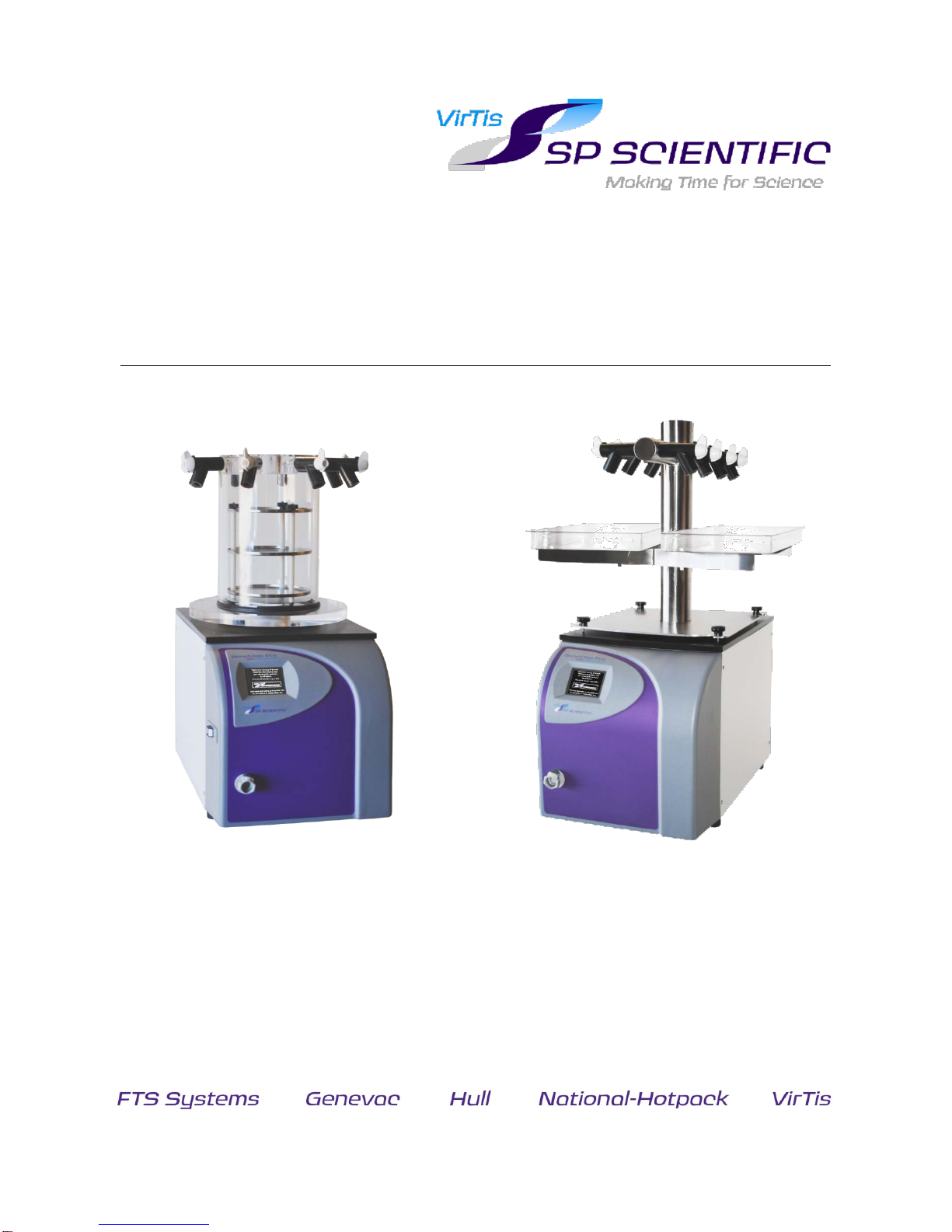
VirTis BenchTop Pro freeze dryers offer a solution for laboratories with space
constraints. Featuring condenser temperatures of -55 °C to -105 °C, BenchTop Pro
freeze dryers can handle a wide range of processing requirements.
Features
Compact design.•
Direct chamber, flask and/or shelf drying capabilities.•
Versatile Omnitronics™ controller with digital display of temperatures•and system status.
Three- to nine-liter condenser capacity.•
Quickseal valves for processing flasks.1•
Manual Stoppering-Tainer (optional).•
BenchTop Pro Usage
BenchTop Pro freeze dryers are mechanically refrigerated condenser modules that
can be utilized as freeze dryers, as well as cold traps and for initial product freezing.
When used in freeze-drying mode, the BenchTop Pro can effectively remove up to
99% of product moisture.
Cold Trap Condenser Module
When using a vacuum concentrator or gel dryer with your BenchTop Pro unit, the
condenser module can be used as a cold trap, trapping vapors driven off the product
before they reach the vacuum pump. To configure a BenchTop Pro unit for a cold trap
application, replace the condenser cover plate or adapter plate with a cold trap
adapter plate and a ¾-inch stainless steel port. For more information, refer to Chapter
4: Cold Trap Condenser.
Note: A low condenser temperature is required when trying to trap organic solvents.
1Requires optional manifold.

Introduction
VirTis BenchTop Pro
2 Rev 002, 01/14
© SP Scientific 2014
Available Configurations
Freeze-drying in the
condenser (3L & 8L Only)
Stainless Steel
Vertical Manifold
Vertical Acrylic Drum
Manifold with Shelf Rack
Stainless Steel
Drum Manifold
Stainless Steel
Tree-Type Manifold
Vertical Acrylic
Drum Manifold

Rev 002, 01/14 3
© SP Scientific 2014
Chapter
2
Installation and Startup
Initial Inspection
Inspect the contents of your shipment immediately upon arrival. Check packing
material for possible small accessory items. DO NOT ACCEPT damaged shipments
from a carrier without a signed notification of damages.
If concealed damage and/or loss is discovered, contact the freight carrier immediately.
Keep the contents, packing material and related paperwork intact until the written
report is obtained.
Note: SP Scientific will cooperate in the matter of collecting your claim, but shall not assume
responsibility for the collection or free replacement of the material. When possible, replacement
parts shall be shipped and invoiced to you, making them a part of your claim.
Lifting Instructions
If no damage was discovered following the initial inspection of the BenchTop Pro unit,
make sure that two (2) individuals are available to safely lift the unit. The BenchTop
Pro should be lifted by the metal frame near the unit’s four (4) feet, not by the front
panel.
WARNING! THE BENCHTOP PRO WEIGHS UP TO APPROXIMATELY
131 LBS (59.4 KG). ALWAYS PRACTICE TEAM LIFTING WHEN MOVING
HEAVY EQUIPMENT.
Lift Here
Lift Here
Do Not Lift at
Front Panel

Installation and Startup
VirTis BenchTop Pro
4 Rev 002, 01/14
© SP Scientific 2014
Service Connections
Make sure that the outlet you intend to use meets the voltage, and amperage
requirements listed on the serial tag of your unit. An IEC 60320 C19 receptacle is
provided with the BenchTop Pro unit. If the plug does not match your receptacle,
contact SP Scientific for replacement or follow the instructions below.
CAUTION! ONLY A QUALIFIED ELECTRICIAN SHOULD CONNECT THE UNIT
DIRECTLY TO THE AVAILABLE ELECTRICAL SUPPLY.
The line cord has three individual conductors inside the outer jacket.2To make the
appropriate plug connection:
Trim back enough of the jacket to facilitate installation of the plug.1.
The three individual conductors are BROWN, BLUE, and GREEN with a2. YELLOW tracer.
Connect the BROWN wire to the line (hot) terminal on the plug.3.
Connect the BLUE wire to the neutral terminal.4.
Connect the GREEN/YELLOW wire to the ground terminal.5.
Vacuum Pump Installation
A remotely mounted vacuum pump is required for the operation of your BenchTop Pro
freeze dryer. The vacuum pump must be a two-stage, rotary vane, dry scroll or
equivalent pump that can achieve at least 20 mT or required process vacuum, that
does not exceed the maximum allowable amperage listed on the unit’s serial tag and
back panel label.
The following parts are included with your BenchTop Pro unit for connection to the
vacuum pump:
Four (4) feet of ¾-inch ID (Inside Diameter) rubber vacuum tubing.•
One (1) 90° rubber elbow•
One (1) plastic connector•
2Consult SP Scientific and a qualified electrician if electrical configurations vary from standard, specified service requirements.

VirTis BenchTop Pro
Installation and Startup
Rev 002, 01/14 5
© SP Scientific 2014
Installing the Vacuum Pump
If you are installing a previously used vacuum pump, refer to the vacuum pump’s
manual and Chapter 6, General Maintenance of this manual. Ensure that the pump
was properly maintained prior to installation. A vacuum pump inlet port adapter and
sufficient tubing are required for connection to the vacuum pump. If you need
assistance, please contact SP Scientific.
Position the vacuum pump in a convenient location near1. the freeze dryer. Ensure that the pump will be easily
accessible during routine maintenance.
Cut the supplied vacuum tubing as short as possible.2. Allow enough length between the vacuum pump and the
BenchTop Pro unit.
Note: Clamp and cut the ¾-inch ID vacuum hose. If you do not
wish to cut the hose, it may be used at its full length, but might
take up more space than necessary.
Locate the inlet port on your vacuum pump.3.
Note: Refer to the vacuum pump’s manual.
Remove any material with the exception of the inlet filter4. screen and gasket.
Place the adapter on the inlet port and secure with a5. fitting. If an adapter is not present, contact SP Scientific.
Remove all objects from the vacuum pump outlet port,6. but retain for future use.
Connect the BenchTop Pro unit to the vacuum pump7. using the ¾-inch vacuum tubing. If connecting to a
vacuum pump purchased from SP Scientific, attach the
¾-inch tubing from the BenchTop Pro to the vacuum
pump intake nipple, add a tubing clamp and tighten
securely.
Check the vacuum pump oil level. The oil level should8. read half way up the sight glass.
Note: Refer to your vacuum pump’s manual for more information.
Add oil only if necessary. Do not overfill!
Vacuum pump

Installation and Startup
VirTis BenchTop Pro
6 Rev 002, 01/14
© SP Scientific 2014
If applicable, check the vacuum pump exhaust piping. SP Scientific suggests9. that the vacuum pump exhaust piping travel horizontally from the pump,
across to a “T” with a drainable trap, then 90° vertically to an outside vent.
Place the trap as close to the pump as possible.
Verify that the power switch on the vacuum pump is off.10.
Verify that the VAC and AUTO buttons on the controller are off (i.e., the11. buttons are not green).
Plug the vacuum pump into the receptacle 60320 C13 marked VACUUM12. PUMP on the back of the unit. The receptacle is an IEC universal outlet. This
allows you to control the pump using the Omnitronics™ controller. The
voltage, phase and frequency of the vacuum pump must match the voltage,
phase and frequency specified on the back panel of the freeze dryer.
Note: You can power your vacuum pump from a wall socket if it does not have an IEC
connector, but you will not be able to control the pump from the Omnitronics™
controller. Only a qualified electrician should perform installation of an IEC connector.
The pump used should not exceed the amperage listed on the BenchTop Pro serial
tag.
Enable power to the vacuum pump by switching the pump’s power switch to13. the on position.
Oil Mist Eliminators
To reduce fumes from the vacuum pump and/or vent the vacuum exhaust externally,
SP Scientific recommends the installation of an Oil Mist Eliminator (OME). An OME
should be installed on the vacuum pump’s exhaust port (i.e., the OUT port located on
the top of the vacuum pump).
Vacuum Exhaust
Piping
Drain for condensed pump oil
and moisture vapors

VirTis BenchTop Pro
Installation and Startup
Rev 002, 01/14 7
© SP Scientific 2014
BenchTop Pro Setup
To set up your BenchTop Pro freeze dryer:
Note: Refer to Chapter 3, Basic Operation for complete equipment operation instructions.
Install the condenser gasket (i.e., black rubber ring with a slit in it) on the top1. of the unit. It should have a light film of vacuum grease on the outer surface.
Note: Only apply a light film of vacuum grease. Over greasing gaskets may contribute
to a failure in system performance.
Prepare the unit for your intended use.2.
a. If the unit is to be used as a standalone freezer, cover the condenser with
a plain cover plate to prevent air circulation from warming the samples.
Skip to step 5.
b. If the unit is to be used as a manifold dryer, place a manifold adapter
plate (i.e., clear acrylic or stainless steel circular disk with a hole) over the
gasket.
a. If you are using an acrylic drum manifold, place a second
condenser gasket (i.e., black rubber ring with a slit in it) around the
bottom lip of the manifold.
b. If you are using a stainless steel drum manifold, place the supplied
O-ring in the groove of the manifold adapter plate.
Note: A manifold O-Ring is different than a condenser gasket.
c. If you are using a vertical or T / tree-type stainless steel manifold, place
the manifold directly on the condenser gasket, locating and locking the 4
notched corners.
NEVER RETIGHTEN THUMBSCREWS WHILE THE SYSTEM IS UNDER
VACUUM.
If using a manifold, attach Quickseal valves to each port on the manifold and3. ensure that each is in the closed position. For more information, refer to the
Quickseal valve section in Chapter 5: Optional Components.
Note: Quickseal valves are siliconized at the factory. Vacuum grease is not required.
Plug the unit into an appropriate outlet and switch on the circuit breaker4. located on the left side of the unit. The Omnitronics™ controller will illuminate.

Installation and Startup
VirTis BenchTop Pro
8 Rev 002, 01/14
© SP Scientific 2014
Vacuum Baffle Plate
The BenchTop Pro 3L and 8L models include a two-position vacuum baffle plate.
Note: A vacuum baffle plate is not available on a BenchTop Pro 9L unit.
Baffle Plate on Chamber Bottom (Position 1).•By raising the baffle plate handle, the plate can be
dropped to the bottom of the chamber. This allows
you to pre-freeze items on the baffle plate. In
some cases, it may be more convenient to remove
the baffle plate completely and freeze items
directly on the bottom of the chamber.
Note: Freeze-drying cannot be performed with the baffle on the chamber bottom
(position1) as the product will remain too cold for water vapor transfer.
Baffle Plate in Raised Position (Position 2).•Lower the baffle plate handle to raise the baffle
plate when freeze-drying products directly on the
baffle. This allows ice to build up on the
condenser below and provides more room for
the materials to be dried.

Rev 002, 01/14 9
© SP Scientific 2014
Chapter
3
Basic Operation
Getting Started
Prior to operating your freeze dryer, ensure that your condenser is clean, dry and
empty.
Product Preparation: Flask/Manifold Drying
BenchTop Pro units include Quickseal valves for processing samples using flasks or
other glassware.
To prepare samples for freeze-drying in glassware:
Fill flasks with your product.3Do not fill more than half of the flask’s total1. capacity. When using Wide Mouth Flasks, ensure that the filter paper and
O-ring are positioned correctly within the flask cover. Snap the cover securely
onto the flask.4
Pre-freeze product samples in a laboratory freezer, dry ice bath or shell bath2. freezer. Freezing to -40 °C is adequate for most products.5
Product Preparation: Drum Manifold Shelf Drying
As an alternative to using flasks, you may use an optional drum manifold and racks to
dry vials of product.
To prepare samples for rack drying:
Fill vials or other suitable containers with product.3Do not fill containers to1. more than half of their total capacity.
Pre-freeze product samples. This can be accomplished directly in the2. condenser of BenchTop Pro 3L and 8L units, or in a laboratory freezer, dry ice
bath or shell bath freezer. Freezing to -40 °C is adequate for most products.5
Note: Pre-freezing directly in the condenser cannot be done in a BenchTop Pro 9L
unit.
If your unit is equipped with the Stoppering-Tainer and you are processing3. product in vials, partially insert a split rubber stopper into each vial.
Load samples onto the shelf (or shelves). If you are using product probes,4. connect the probes to the thermocouple jacks provided.
3Refer to Appendix B for a list of standard serum vial capacities.
4Wide Mouth Flasks are the most popular glassware type, but other types of flasks, vials and ampoules are available. If you are
not certain how to use glassware accessories, contact SP Scientific.
5Dry ice methods can freeze a product to approximately -78 °C, while liquid nitrogen (N2(liq)) methods can freeze a product to
approximately -190 °C.
Basic Operation
VirTis BenchTop Pro
10 Rev 002, 01/14
© SP Scientific 2014
Product Preparation: Chamber Drying
BenchTop Pro 3L and 8L freeze dryers can process product in vials or trays directly in
the condenser chamber.
Note: Processing products in vials or trays directly in the condenser cannot be done in a
BenchTop Pro 9L unit.
To process samples in the chamber:
Fill a tray or vials with your product.6Do not exceed more than half of the1. container’s total capacity.
Ensure that the vacuum baffle plate is in the desired position (i.e., position 12. for pre-freezing or position 2 for freeze-drying).
Note: Refer to Chapter 2, Vacuum Baffle Plate for further information.
Close and secure the chamber lid.3.
PRACTICAL OPERATING TIP. TO MINIMIZE DRYING TIME, ALWAYS FREEZE PRODUCTS
IN AS THIN A LAYER AS POSSIBLE. NEVER FILL A CONTAINER TO MORE THAN HALF
ITS TOTAL CAPACITY.
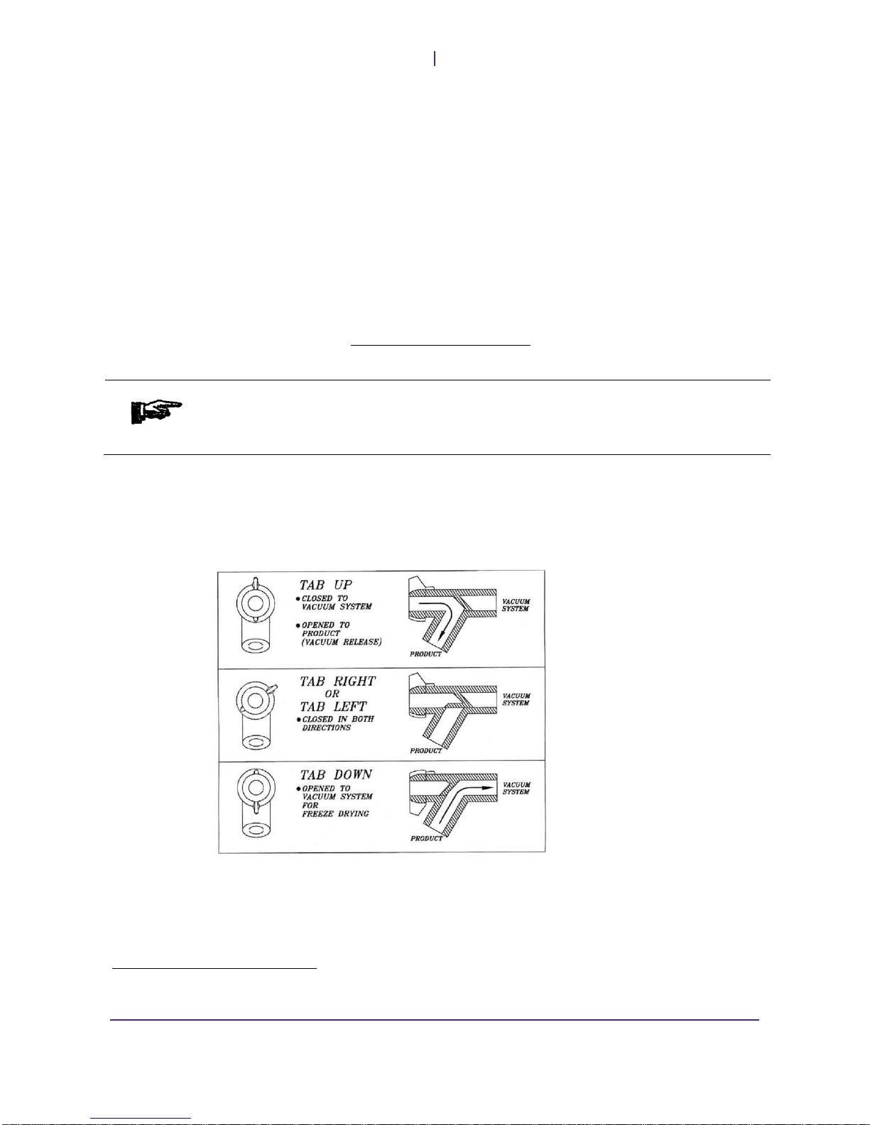
Quickseal Valves
Quickseal valves are utilized in many methods of drying. They permit the attachment
of flasks for in vitro freeze-drying. They may also be used to break vacuum after a
cycle completes. Quickseal valves operate as follows:
Note: Quickseal valves are an integral part of the freeze-drying process and must be
maintained as such. For information regarding upkeep and service of Quickseal valves, see the
General Maintenance section of this manual.
6Refer to Appendix B for a list of standard serum vial capacities.

VirTis BenchTop Pro
Basic Operation
Rev 002, 01/14 11
© SP Scientific 2014
Basic Operation Instructions
Ensure that the condenser is clean, dry and empty before proceeding. Check1. the drain line for residual moisture, which can cause slow vacuum pump-
down.
Ensure that the plastic quick-connect drain fitting is not inserted into the drain2. fitting receptacle on the front of the unit.
Pre-freeze the product to a minimum of -40 °C.3.
Check that all connections and ports are secure. Ensure that Quickseal4. Valves are closed.
Press the COND button to begin cooling the condenser. Wait for the
condenser to reach the controller’s Condenser Threshold setpoint
(i.e., -40 °C). Before proceeding, confirm that the condenser temperature on
the System Status screen has reached the Condenser Threshold setpoint
(i.e., -40 °C).
Alternatively, press the AUTO button and allow the system to proceed
through the freeze-drying process using the controller’s settings. If using the
AUTO function, skip to step 7.
Note: The Condenser Threshold setpoint is configured at the manufacturing facility.
Enable vacuum by pressing the VAC button. Allow the system to evacuate.5. Before proceeding, confirm that the current vacuum level displayed on the
System Status screen is at the desired vacuum level.
Note: If your vacuum pump is not connected to the BenchTop Pro unit, the
Omnitronics™ controller will not be able to enable it. Switch on the vacuum pump
manually. See your vacuum pump manual for more information.
Add product as appropriate:6.
If using a manifold, attach a flask to a Quickseal valve and turn the valve•to the open position to begin the freeze-drying process. Allow the
vacuum level to recover to your vacuum control setpoint (at least 200
millitorr) before connecting additional flasks.
If using a vacuum concentrator with your BenchTop Pro, add samples•and begin spinning.
Note: For more information, refer to Chapter 4, Cold Trap Condenser.
Ensure that critical system parameters stay within the acceptable ranges7. (i.e., refrigeration and vacuum). The condenser temperature and vacuum
pressure values displayed on the System Status screen appear as green or
red, providing an easy status check. Periodically check the condenser for ice
build-up and defrost as needed.
Observe the product to determine when drying is complete. For manifold8. drying, the drying process is typically complete when the exterior glassware
reaches ambient temperature and the product appears dry
(i.e., approximately 90 to 95% of the moisture has been removed). Lower
moisture content may be achieved by allowing the product to continue to dry
for several hours.

Basic Operation
VirTis BenchTop Pro
12 Rev 002, 01/14
© SP Scientific 2014
For heated shelf and chamber drying, the process is complete when one or9. more of the following conditions are met:
The condenser approaches its maximum low temperature.•
System vacuum approaches a constant low pressure reading.•
Appearance of the product indicates dryness (i.e., uniformly powdery or•fluffy).
Switch off the vacuum and refrigeration systems. If running an automatic10. cycle, press the AUTO button to disable both systems simultaneously.
For manifold flask drying, close Quickseal valves and remove flasks. If using11. a vacuum concentrator, turn off the unit and close Quickseal valves. If using a
chamber or manifold with shelves, break vacuum and remove the product.
If your system is still under vacuum, release vacuum by inserting the drain12. plug into the drain fitting or by opening a Quickseal valve.
After removing all product, press the DEFR button to enable condenser13. defrost. The defrost function allows ice to be lifted out of the condenser
without fully melting. A drain line is connected to a plastic quick-connect
fitting, which is then inserted into the drain receptacle on the front of the unit.
To open the drain, push the fitting into the drain receptacle. To close the drain
line, press the small gray release button on the top of the receptacle. The
fitting will pop out.
Note: The quick-connect fitting must be removed prior to freeze-drying or the
appropriate vacuum pressure will not be achieved.
Once the ice has melted away from the condenser, the ice can be removed.14. Thoroughly clean and rinse the condenser with a mild detergent or baking
soda solution (to neutralize acids).
Note: Do not chip away at the ice, as this may damage the condenser. Refer to
Appendix D, Chemical Resistance Charts for further information.
The defrost system turns off automatically after one (1) hour or when the15. condenser reaches 60.0 °C (140.0 °F). To deactivate the defrost process
manually, press the green DEFR button.
Table of contents
Other SP Scientific Laboratory Equipment manuals


Popular Laboratory Equipment manuals by other brands

Grant
Grant SAP Series Service manual

RR Mechatronics
RR Mechatronics STARRSED TL user manual

Optika Italy
Optika Italy Modular Series instruction manual

Tamson Instruments
Tamson Instruments TV12LT user manual

Endress+Hauser
Endress+Hauser Liquiline Control CDC90 operating instructions

Element
Element ELCG-02ASP instruction manual


