UMS HYPROP User manual

Operation Manual
HYPROP
This manual is also available in German:
http://www.ums-muc.de/static/Bedienungsanleitung_HYPROP-VIEW.pdf

At a glance – how it works
Evaporation
Soil sample
Sampling ring
Balance
Tensio Top
Tensio Bottom
to USB
interface
Pressure sensors
Sensor unit
HYPROP®is a fully automated measuring and evaluation system to
determine the hydraulic properties of soil samples. HYPROP measures
the water tension at two levels of a sample using two tensio shafts. If the
conductivity of the sample is poor the soil in the upper horizons dries
out whereas the lower horizons are still humid. So the upper tensio shaft
measures much drier tensions than the lower one which is still humid. If the
conductivity is good water is evaporated out of the whole sample and
both tensions are almost identical. The water content for the pF/WC curve
is calculated based on the weight loss of the sample.
This measuring concept is based on Schindler’s method. Please find further
information in the chapter “Theory”.
Legend
water electronics soil
water vapor ceramic all other parts cross section of a part

Parts of the device
and scope of delivery
sample ring
sensor unit
O-ring (red)
for sealing the tensio shafts
to the pressure sensor
ceramic
shaft
silicone gasket
tensio shafts
O-ring (black)
for dirt protection
balance
Note
This manual does not describe the evaluation of the measuring data using the HYPROP-FIT
software. For this please find another manual:
http://www.ums-muc.de/static/Manual_HYPROP-FIT.pdf

Additional parts
in the scope of delivery
sensor unit
O-rings
tensio shafts
50 mm and 25 mm HYPROP
connecting cable
plastic caps silicone gasket and
nonwoven cloths
tensioLink®
T-piece
refilling attachment
for sensor unit saturation plate
5 | Scope of delivery

droplet syringe
tensio shaft auger tube for vacuum syringe
and attachment for sensor unit
vacuum syringe reservoir syringe
6 | Scope of delivery

auger guide
sample ring 250 ml
with plastic caps deionized water power device
HYPROP USB adapter
7 | Scope of delivery

8 | Content
Contents
At a glance – how it works ................................................................................... 2
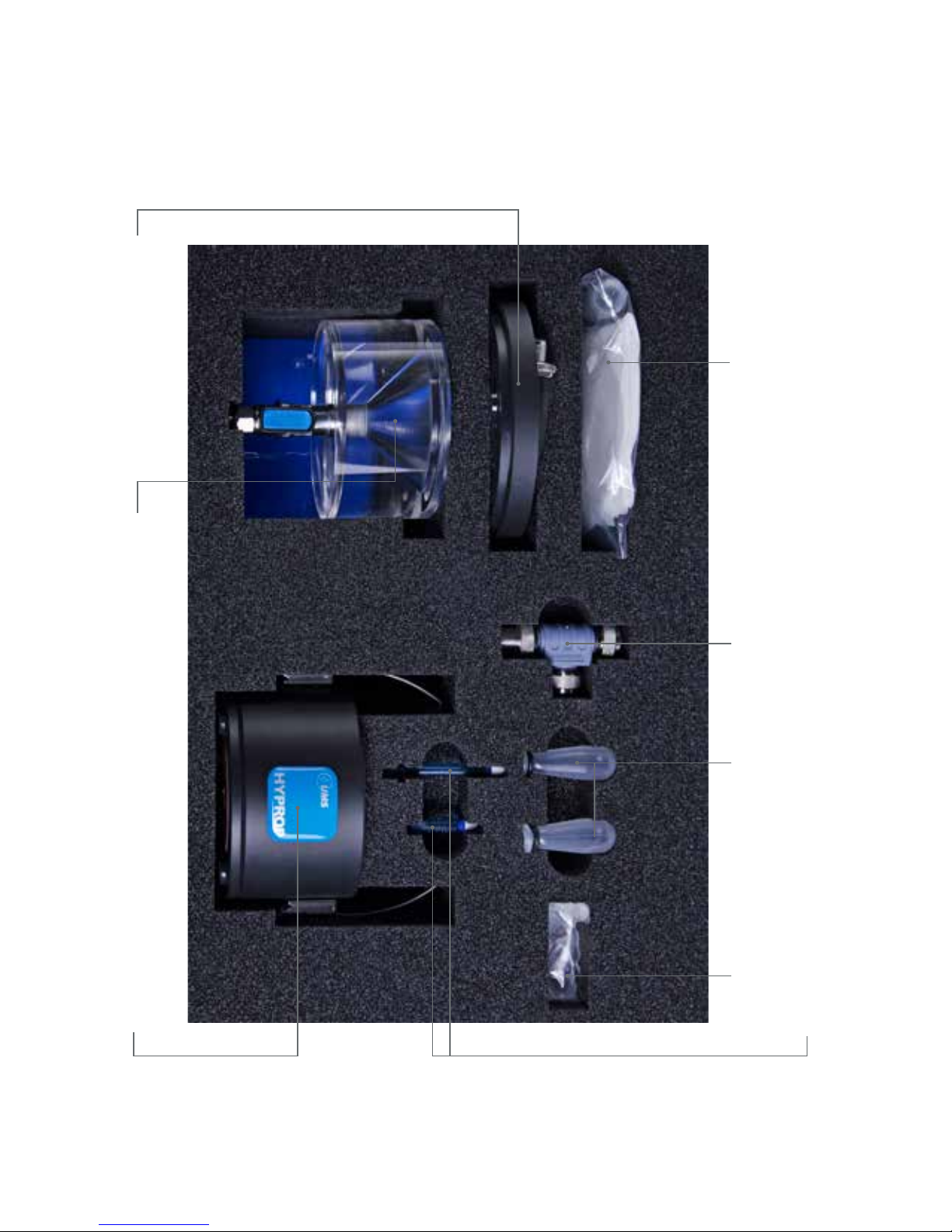
Parts of the device and scope of delivery .......................................................... 3
Important information ......................................................................................... 10
Safety instructions ............................................................................................10
Intended use ....................................................................................................10
Warranty ...........................................................................................................10
HYPROP-VIEW software functions ....................................................................... 11
Key functions ....................................................................................................11
User support .....................................................................................................11
Show devices ...................................................................................................12
Device tree ......................................................................................................13
Initial operation .................................................................................................... 16
Software installation: HYPROP-VIEW and HYPROP-FIT .................................16
Hardware configuration ..................................................................................17
How to use the tube connections .................................................................18
General measuring procedure .......................................................................... 19
Preparing the measurement .............................................................................. 20
Saturating the soil sample ..............................................................................20
Filing the device ..............................................................................................22
using the Refill Unit (accessories) ..........................................................23
using syringes ...........................................................................................28
Offset recalibration ..........................................................................................41
Implementing the tensio shafts in the sensor unit ........................................43
Attaching the dirt protection .........................................................................46
Function check ................................................................................................47
Assembling the sensor unit and the soil sample ..........................................49
Connecting the sensor unit and the balance .............................................51
Preparing the balance ...................................................................................53
Adjusting............................................................................................................55
Default settings .................................................................................................57
Measuring ............................................................................................................ 58
Multi balance mode (one balance per sensor unit) ..................................58
Single balance mode (one balance for more sensor units) ......................59
Optimal measuring curve ................................................................................... 61
Notes on suboptimal measuring curves .......................................................63

Finishing a measurement .................................................................................... 64
Determining the dry weight ................................................................................ 67
Weighing the dry mass ....................................................................................68
Evaluating the measurement ............................................................................. 69
Trouble shooting .................................................................................................. 70
Cleaning and maintenance ............................................................................... 71
Cleaning the sensor unit .................................................................................71
Changing the O-rings in the sensor unit .......................................................72
Storage .............................................................................................................73
Additional accessories ....................................................................................... 74
Theory ................................................................................................................... 76
Preliminary note ...............................................................................................76
Measuring method ..........................................................................................77
Explanation of terms ........................................................................................78
Generating data points ..................................................................................80
Additional notes ..............................................................................................82
Addendum ........................................................................................................... 83
Typical measuring curves ...............................................................................83
Standard pF curves .........................................................................................90
Procedure of sampling for WP4 measurements
after a HYPROP measurement .......................................................................91
Units for soil water and matrix potentials ......................................................91
Facts and figures ................................................................................................. 93
Technical data ................................................................................................93
Literature cited ..................................................................................................... 94
9 | Content

Important information
10 | Important information
Electrical installations must meet the safety and EMC requirements of the
country in which the system is used. Damages caused by the user are not
covered by the warranty. HYPROP is a device to measure soil tensions as well
as soil water pressures and temperatures and is only intended for this parti-
cular use. Please keep the following notes in mind:
Note
Please do not touch the ceramic of the tensio shafts with bare fingers. Grease or soap
reduces the hydrophilic characteristics of the ceramic.
Note
Do not stick sharp objects into the holes of the sensor unit. You may damage the
pressure sensor.
Intended use
Safety instructions
Warranty
HYPROP®is a measuring system that is intended to be used for measuring the
water retention function and the hydraulic conductivity as a function of the
water tension or the water content of soil samples.
UMS offers a warranty for material and production defects for this device in
accordance with the locally applicable legal provisions, but for a minimum
of 12 months. The warranty does not cover damage caused by misuse, inex-
pert servicing or circumstances beyond our control. The warranty includes
replacement or repair and packing but excludes shipping expenses. Please
contact UMS or our representative before returning equipment. Place of ful-
fillment is Gmunder Str. 37, Munich, Germany.

Software functions
The key functions are:
•displaying the connected devices,
•displaying the measurement data
•filling assistant
•measurement configuration wizard
The wizard is explained in the respective chapter.
User support
Key functions
Example of user support: Help Function
Note
After starting the software the user support leads you through all software functions.
If you are an experienced user you may not like to use the wizard of the measuring
configuration and enter the data directly instead. This is possible too.
When you start the software and the help
function is activated notes of the next
step are displayed, e.g. here you are
asked to click on the “Show device” icon.
11 | Software functions

Show connected devices
Click on an icon in the upper screen bar
e.g. “Measurement”.
Click on the icon “Show devices”.
In case a balance does not show, check
if the balance is switched on.
Follow the wizard.
When all steps are done, click on “Apply”
if you want to enter the configuration.
If you click on “Cancel” you return to the
initial page, where you have opened the
wizard.
Data you have entered are set in the
program.
All connected balances and sensor
units are displayed.
Example of user support: Wizard
12 | Software functions

The device tree (example)
Sensor unit “soil lab 18” is connected to
the computer via a HYPROP balance.
Sensor unit “soil lab 15” is connected
to the computer via the USB adapter.
A Kern balance is connected to
the computer via a RS232 interface.
Sensor unit “soil lab 17” is connected to
the computer via a HYPROP USB Cable.
13 | Software functions

Main window with manager
Mode (one or
more balances)
Connected
devices
One measurement
file per soil sample is
generated
Data to be typed
in by the user
Device ID
(click right mouse
button to change)
Short cuts to
key functions Unit Link to the HYPROP-FIT
software
Next step
Switches to displaying
the measurement
values when a mea-
surement is running
Default folder for
measurement files
Interrupt, stop or start
all measurements
14 | Software functions

Main window with measurement values
Stops the
measurement
Runs an immediate
measurement
Display of the soil sample’s
tensions and weights over
time (graphical)
Display of the soil sample’s
tensions and weights over
time (tabular)
Opens the measurement
file in HYPROP-FIT when
the measurement
is running
Deletes all measurements
performed
15 | Software functions

Initial operation
Put the CD with the HYPROP software into
the computer. If you do not have a CD
download the software using the link
http://www.ums-muc.de/static/
HYPROP-VIEW.zip
http://www.ums-muc.de/static/
HYPROP-FIT.zip.
Double click on Setup.exe
Follow the wizard.
Connect the HYPROP balance
to the USB port.
Start the HYPROP software.
The wizard leads you through the
installation.
The balance connects automatically
to the computer.
Your HYPROP is ready to measure.
Note
For installing the HYPROP software you may need administrator rights.
Software installation: HYPROP-VIEW and HYPROP-FIT.
16 | Initial operation

Hardware configuration
Change device ID
Each sensor unit needs its particular device ID otherwise a communication
collision may occur.
Click on device with right mouse button.
Click on “apply”.
Choose “Chance Device ID”.
Choose an available ID from the
pulldown menu.
Click on device with right mouse button.
Choose “Rename”.
Click on “apply”.
Change device name (optional)
17 | Initial operation

Note
Cut the tube always rectangular otherwise the connection will be leaking.
To connect the tube to the fitting push the tube in as far as it will go.
To remove the tube press blue ring and pull.
How to use the tube connections
18 | Initial operation

General measuring procedure
A measurement consists of the following steps:
•soil sampling and preparation
•saturating the soil sample
•preparing the measuring system
•setting up the sample in the measuring system
and starting the measuring campaign
•evaluating the measuring results with HYPROP-FIT.
In the following this manual will guide you through the measuring
process step-by-step.
19 | General measuring procedure

Take the sample ring with soil out of the
transport box and clean it. Prepare top
and bottom side of the sample (e. g. with
a saw blade).
Put a plastic cap upside down on the
sample ring – on the side where the ring
has the cutting edge. The cap works
as a support. This makes sure that no
soil gets lost even when loose sand is
in the sample ring.
Preparing the measurement
Saturating the soil sample
20 | Preparing the measurement
Turn soil sample upside down and put it
on a table. Remove cap on top, place
nonwoven cloth on the soil and put the
filling bowl on the sample ring.
Turn soil sample again upside down.

Note: Recommended time for saturation
Material Refilling after Aufgesättigt nach
Coarse sands about 9 min about 10 min
Fine sands about 45 min about 1 h
Silts about 6 h about 24 h
Clay n. a. up to 2 weeks
Raise the water level up to 5 mm below
the sample rim (recommended times
see below). Do not pour water on the
sample – you may trap air. Use the time
table below as a reference to determine
how long samples take to saturate.
Fill 2 cm (1 in) of degassed water into a
tray. Put the soil sample into the tray – tilt
it so that air under the soil can escape.
Let soil sample capillary saturate until the
surface is shining.
Put a plastic cap upside down on the
sample ring. Do not fix it so that air can
ventilate. The cap protects the soil from
sun radiation and evaporation.
21 | Preparing the measurement
Other manuals for HYPROP
2
Table of contents
Other UMS Laboratory Equipment manuals
Popular Laboratory Equipment manuals by other brands

YOKOGAWA
YOKOGAWA DL850E user manual

Thermo Scientific
Thermo Scientific Sorvall ST40R instruction manual

10x Genomics
10x Genomics Chromium Controller Readiness Test manual

Gilson
Gilson Pipetman P2G user guide

Miele
Miele APLW 631 operating instructions

Lifecanvas Technologies
Lifecanvas Technologies SmartBatch+ user manual