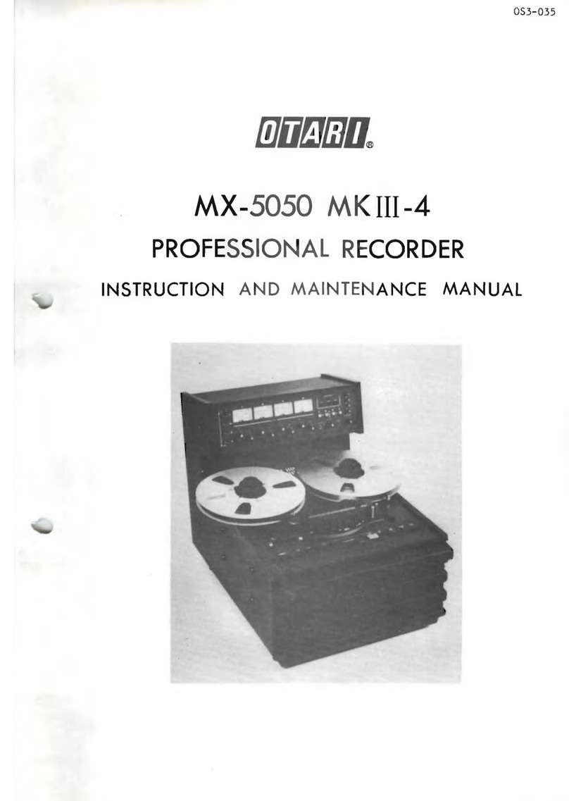
OTARI MX-5050MKIII-2 User manual

Parts No. OS3-042
MX-5050MKIII-2
PROFESSIONAL RECORDER
OPERATION MAN AL
Richard L. Hess
Audio Tape Restoration
I-877-TAPE-FIX
(Toll Free U S. S Canada)
14845-6 Yonge Street
Suite 124
Aurora ON L4G 6H8
CANADA
(905) 713-6733 (V)
(905) 751-1984 (F)
http://www.richardhess.com/tape/
richard@richardhess.com
Edition No. 3
Printed : Feb. 1986

CA TION
To prevent fire or shock hazard :
Do not expose this appliance to rain or moisture.
Do not remove cover.
No user-serviceable parts inside.
Refer servicing to qualified service personnel.
PLEASE READ THRO GH SAFETY INSTR CTIONS
ON THE NEXT PAGE.

SAFETY INSTR CTIONS
1.
2.
3.
4.
5.
6 .
7 .
8 .
9.
10.
11.
12 .
13 .
14.
Read Instructions — All the safety and o erating instruc
tions should be read before the a liance is o erated.
Retain Instructions — The safety and o erating instructions
should be retained for future reference.
Heed Warnings — All warnings on the a liance and in the
o erating instructions should be adhered to.
Follow Instructions — All instructions should be followed.
Water and Moisture -— The a liance should not be used near
water - for exam le, near a bathtub, washbasin, kitchen sink,
laundrytub, in a wet basement, or near a swimming ool, etc.
Carts and Stands — The a liance should be used only with
a cart or stand that is recommended by the manufacturer.
Ventilation — The a liance should be situated so that its
location or osition does not interfere with its ro er
ventilation.
For exam le, the a liance should not be situated on a bed,
sofa, rug, or similar surface that may block the ventilation
o eratings; or, laced in a built-in installation, such as a
bookcase or cabinet that may im ede the flow of air through
the ventilation o enings.
Heat — The a liance should be situated away from near
sources such as radiators, heat registers, stoves, or other
a liances (including am lifiers) that roduce heat.
Power Sources — The a liance should be connected to a
ower su ly only of the ty e described in the o erating
instructions or as marked on the a liance.
Grounding or Polarization — Precautions should be taken so
that the grounding or olarization means of an a liance are
not defeated.
Power-Cord Protection — Power-su ly cords should be routed
so that they are not likely to be walked on or inched by
items laced u on or against them, aying articular atten
tion to cords at lugs. Convenience rece tacles, and the
oint where they exit from the a liance.
Cleaning — The a liance should be cleaned only as recom
mended by the manufacturer.
Nonuse Periods —— The ower cord of the a liance should be
un lugged from the outlet when left unused for a long eriod
of time.
Object and Liquid Entry — Care should be taken so that

WARNING
This equipment generates, uses, and can radiate
radio frequency energy and if not installed and
used in accordance with the instructions manual,
may cause interference to ratio communications.
It has been tested and found to comply with the
limits for a Class A computing device pursuant to
Subpart J of Part 15 of FCC Rules, which are de
signed to provide reasonable protection against
such interference when operated in a commercial
environment. Operation of this equipment in a re
sidential area is likely to cause interference in
which case the user at this own expense will be
required to take whatever measures may be re
quired to correct the interference.

COMM NICATION WITH OTARI
FOR SERVICE INFORMATION AND PARTS
The OTARI PRODUCTS are manufactured under strict quality control
and each unit is carefully tested and ins ected rior to shi ment
from our factory.
If, however, some adjustments or technical su ort become neces
sary, re lacement arts are required, or technical questions arise,
lease contact your nearest Otari dealer or write to:
OTARI CORPORATION
2 Davis Drive, Belmont,
California 94002, U.S.A.
Phone: (415) 592-8311
Telex: 25 9103764890
Fax : (415) 591-3377
OTARI SINGAPORE PTE., LTD.
625 Aljunied Road #07-05
Aljunied Industrial Com lex,
Singa ore 1438
Phone: 743-7711
Telex: 87 36935 RS36935 OTARI
Fax : (743) 6430
OTARI ELECTRIC (UK) LTD.
22 Church Street Slough Berkshire SLl 1PT
United Kingdom
Phone: SLOUGH (0753) 822381
Telex: 849453 OTARI G
Fax : (0753) 823707
OTARI ELECTRIC CO., LTD.
4-29-18, Minami Ogikubo,
Suginami-ku, Tokyo, 167, Ja an
Phone: (03) 333-9631
Telex: J26604 OTRDENKI
Fax : (03) 331-5802
OTARI ELECTRIC DEUTSCHLAND GmbH.
Gielenstrasse 9, 4040 Neuss 1
F.R. Germany
Phone: 02101-274011
Telex: 41 8517691 OTEL D
Fax : (02101) 222478
Another art of Otari's continuous technical su ort rogram for
our roducts, is the continuous revision of manuals as the equi
ment is im roved or modified.
In order for you to receive our information and service a licable
to your requirements, and for the technical su ort to function
ro erly, lease include the following information, most of which
can be obtained from the name late on the equi ment in all
corres ondences.
1. Model Number
2. Serial Number
3. Date of urchase
4. Name and address of dealer from whom machine was
urchased
5. Power requirements (voltage and frequency) of the
machine
6. Manual number to which you are referring
VII

TABLE OF CONTENTS
PAGE SECTION TOPIC
IGENERAL INFORMATION
1-1 1.1 System Descri tion
1-1 1.1.1 Ta e Trans ort
1-3 1.1.2 Record/Re roduce Electronics
1-3 1.1.3 Head Assemblies
1-4 1.2 Standard Accessories
1-4 1.3 O tional Accessories
1-5 1.4 Service and Re lacement Parts
1-5 1.5 S ecifications
II INSTALLATION
2-1 2.1 Un acking and Ins ection
2-1 2.2 Cable Connection
2-1 2.3 Location and Environment
2-2 2.4 Dimensions
2-3 2.5 Standard Switch Position on Shi ment
2-4 2.6 Power and Signal Connections
2-8 2.6.1 AC Power Connections
2-8 2.6.2 Signal Connections
III OPERATION
3-1 3.1 Controls and Indicators
3-9 3.2 O erating Informatin
3-9 3.2.1 Use of the Reel Hold Down Knobs
3-10 3.2.2 Pre-o erating Procedure
3-11 3.2.3 Re roduction
3-12 3.2.4 Normal Recording
3-13 3.2.5 Recording with Selective Production
3-14 3.2.6 Fast Winding
3-14 3.2.7 Editing and S licing Ta e
IV GENERAL INFORMATION OF MAINTENANCE
i—i
i
4.1 Test and Maintenance Equi ment Requirement
V ROUTINE MAINTENANCE AND CONVERSION
INFORMATION
5-1 5.1 Routine Maintenance
5-1 5.1.1 Cleaning
5-2 5.1.2 Demagnetizing
5-3 5.1.3 Lubrication
5-4 5.2 Ta e Re lacement
5-5 5.3 Equalizer Change
5-5 5.4 Line Voltage Conversion
5-7 5.5 Fuse Re lacement
5-9 5.6 S eed Conversion
VI P.C.B. ASSEMBLIES AND PARTS LISTS
VII EXPLODED VIEW DRAWINGS AND PARTS LISTS
VIII PATTERN LAYOUT
IX

SECTION I. GENERAL INFORMATION
The MX-5050 MK HI-2 Recorder is a rofessional quality two-s eed
audio ta e recorder/re roducer, designed for o timum erformance
and long life. It accommodates a 1/4 inch ta e, 7-1/2 i s (19.05
cm/sec) and 15 i s (38.1 cm/sec) ta e s eeds.
1.1 SYSTEM DESCRIPTION
Among the many rofessional features of the MX5050MKHI-2 are:
selective re roduction, motion sensing, an edit control that
ermits s illing, an adjustable cueing control for audible moni
toring in the fast-forward and rewind modes, a built-in two
frequency low distortion test and cue-tone oscillator, a com
uterized ela sed time indicator with a digital LED dis lay,
front adjustable record bias, equalization, and level controls,
active balanced in ut and out ut circuits, a reference flux level
indicator on the front am lifier anel, a standard reference
level out ut switch, se arate line and micro hone in ut level
controls for each channel, switches for recording levels, equal
ization, micro hone, and out ut level attenuators, lay-back
equalization ots for each s eed, a memory sto button for auto
matically searching the zero ta e time location with F. FWD or
RWD mode, ceramic ta e guides, big head housing, lower trans ort
noise, and xm roved s ecifications for distortion, erase effect,
and signal and noise ratio.
1.1.1 TAPE TRANSPORT
All com onents of the ta e trans ort system are mounted on a
rigid aluminum frame for stability. The trans ort design in
cor orates two 6- ole induction motors for the reels and a 3-
s eed DC servo motor (Direct drive) for the ca stan.
S eed selection is made by a front anel ush-button switch which
also switches the equalizer.
The trans ort accommodates ta e reels of 10-1/2 inches, 7 inches,
and 5 inches in diameter with NAB or EIA hub configurations. A
solenoid-actuated ta e lifter lifts the ta e away from the heads
in the fast forward and rewind modes, in addition to the sto
mode, to increase head and ta e life.
In addition to the editing controls, a ta e-s licing block (Fig.
3-3) mounted on the head cover holds the ta e for ease of editing
Momentary contact ush-button switches on the trans ort are used
to select o erational modes: record, lay, sto , rewind, and
fast forward. These modes may be controlled from a remote loca
tion by means of an o tional remote control unit ( age 1-5).

1.1.2 RECORD/REPRODUCE ELECTRONICS
FEATURES
(1) The RECORD/REPRODUCE am lifier unit is connected to the
trans ort unit only by the connectors and therefore can be
easily removed for ease in servicing.
(2) This machine contains a SEL. REP. function for overdubbing:
for exam le, SOUND WITH SOUND, SOUND ON SOUND, carried out
by the PUNCH-IN and PUNCH-OUT functions of the trans ort
control.
(3) This machine rovides both NAB and IEC equalizers, switchable
on the rear anel. However, when the equalizer osition is
changed, fine tuning the record and re roduce equalizer
adjustment controller is necessary.
(4) In order to give o timum erformance for different ty es of
recording ta es, record bias, level, and equalization con
trols on the front anel can be adjusted to meet any
requirements.
(5) To im rove the signal to noise ratio and increase the head
room, the record/re roduce electronics have been designed
with a high-fidelity am lifier.
1.1.3 HEAD ASSEMBLIES
As viewed from the front of the recorder, the configuration of the
head assembly of model MX-5050 MKIIt-2 is shown in Table 1-1.
Table 1-1 Head Assembly Configuration
Head Structure Record
Head
HI
Erase H2
Playback H3
Record H4
Playback
2T, 2CH 4T, 2CH 2T, 2CH 2T, 2CH 2T, 2CH
Stereo
1-3

OPTIONAL ACCESSORIES
1. Remote Control Unit
2. Auto Locator
3 . Cleaning Kit
4. Balanced In ut Transformer Ass'y
5. Balanced Out ut Transformer Ass'y
6. Hold Down Knob (for EIA hub)
CB-102
ZA-54C (CB-116)
ZA-51B
ZA-53T
ZA-53S
ZA-52Y
1.4 SERVICE AND REPLACEMENT PARTS
For service and re lacement arts, or for technical su ort,
lease contact your nearest service center, OTARI dealer, or write
directly to OTARI. (See age iii for com lete addresses.)
1.5 SPECIFICATIONS
The s ecifications of the MX-5050 MKIH-2 are as listed in Table
1-2 .
NOTE: S ecifications are based on ta e s eeds of 7-1/2 and 15
i s. S ecifications, although obtainable when serviced by
qualified service ersonnel, are not guaranteed when using
lower ta e s eeds.
Table 1-2 S ecifications of the MX-5050 MKHL-2
Ta e Width and Tracks 1/4 inch (6.3 mm) ta e:
2 tracks (0.079 in. or 2.0 mm
track width)
Ta e S eeds 7-1/2 and 15 i s (19 and 38 cm/sec) or
3-3/4 and 7-1/2 i s (9.5 and 19 cm/sec)
Maximum deviation: ± 0.2 % measured
with 1.5 mil (0.038 mm) ta e.
Reel Sizes 7 inch or 10-1/2 inch lastic or
metal, EIA or NAB.
Heads Half-track configuration.
Four head stacks:
2T erase, 4T re roduce,
2T record, 2T re roduce.
1-5

Out uts: Line
Head hone
Level: +4 dBm or -10 dBm, rear anel
switch selectable.
Active balanced (Floating ty e),
Source im edance: 5 ohms.
Load im edance: More than 600 ohms.
Maximum line out ut: +27 dBm with a
600 ohm load.
Level: -24 dBm with an 8 ohm load.
Load im edance: 8 ohms or greater.
Equalization NAB or IEC for 3-3/4, 7-1/2, and
15 i s.
Switchable on the rear anel, but
calibration is necessary.
Frequency Res onse 15 i s : 30 Hz to 20 kHz ± 2 dB
7-1/2 i s: 20 Hz to 18 kHz + 2 dB
3-3/4 i s: 20 Hz to 10 kHz ± 2 dB
S ecifications refer to a 1 kHz refer
ence when recorded on 3M 226.
Signal to Noise Ratio Over-all measured at the level of 520
nWb/m.
NAB Equalization:
Ta e S eed Weighted Unweighted
15 i s 6 6 dB 64 dB
7-1/2 i s 6 8 dB 6 8 dB
3-3/4 i s 66 dB 64 dB
IEC Equalization:
Ta e S eed Weighted Unweighted
15 i s 6 7 dB 65 dB
7-1/2 i s 66 dB 64 dB
3-3/4 i s 66 dB 64 dB
1-7

NOTES: 1. Signal to noise ratio is measured with res ect to a
recorded level of 520 nWb/m to biased ta e noise when
using Scotch 226 magnetic ta e.
Unweighted: Using a 30 to 18 kHz RC filter to atten
uate noise outside the audio s ectrum.
Weighted : Using an NAB or ASA "A" weighting filter
and a 1 kHz reference.
2. Otari reserves the right to change s ecifications
without notice and/or obligation.
1-9

SECTION II. INSTALLATION
This section of the manual rovides information on un acking and
ins ection, location and environment, and ower and signal
connections.
2.1 UNPACKING AND INSPECTION
The MX-5050 MKIH-2 system is shi ed from the factory in a single
cardboard acking case. U on recei t, examine the case for any
signs of damage. Un ack the equi ment and ins ect for any signs
of damage. Use great care when un acking the equi ment and remov
ing acking materials to revent damage to critical com onents
such as the ca stan, head assembly, and tension arms.
Referring to the lists in Secs. 1.2 and 1.3 (as a licable), veri
fy that all items have been received. Re ort any shortage or
damage to the carrier and your local Otari dealer. Save the
acking case for ossible reshi ment. Other ackaging may cause
damage during trans ortation and will void the warranty.
Please refer to the illustration which is attached to fla of the
acking box regarding the re acking method.
2.2 CABLE CONNECTION
Before installing the machine on the lace you desire, you should
connect the each cable to the ro er connector on the am lifier
unit as described below. (One end of each cable is already linked
to the connector on the trans ort rear anel.)
Table 2-1 Cable Connection
Trans ort Unit Am lifier Unit
1TO AMP connector TO DECK connector
2RECORD/ERASE HEAD connector RECORD/ERASE HEAD connector
3REPRODUCE HEAD connector REPRODUCE HEAD connector
2.3 LOCATION AND ENVIRONMENT
The area chosen for o eration should be adequately ventilated and
dust free. Since recording is by an electromagnetic rocess, it
is ossible that strong electromagnetic fields may affect the
system adversely. Common sources of interference are fluctuating
loads on nearby high-voltage lines, heavy duty transformers, and
transmitting equi ment.
2-1

2.5 STANDARD SWITCH POSITION ON SHIPMENT
Either the NAB standard or the IEC standard of equalization,
recording level, etc. may be used with the Otari MX-5050 MKHI-2.
These units have been rovided with a slide switch on the back
anel which selects one of these two standards; to change stand
ards, merely slide the switch to the desired osition.
Fig. 2-2(a) Standard Switch Position on Shi ment (NAB)
Fig. 2-2(b) Standard Switch Position on Shi ment (IEC)
Table 2-2 Standard Switch Position on Shi ment
Switch Ref. No. Tyi
NAB
>e
IEC
OUTPUT LEVEL 1HIGH HIGH
EQUALIZER 2NAB IEC
RECORD LEVEL 3 M H
MIC. ATT 4OFF OFF
2-3

Index
No. Name Function
1REMOTE CONTROL
Connector Remote control connector for use
with the o tional remote control
unit to control the record, lay,
sto , rewind, and fast forward
modes.
2 LINE OUTPUT
Connector Male XLR-ty e connector.
Active balanced out ut
(Floating ty e).
Source im edance: 5 ohms
Load im edance: 600 ohms or
greater.
Level: +4 dBm or -10 dBm at 0 VU
switchable by the OUTPUT
LEVEL switch.
3LINE INPUT Connector Female XLR-ty e connector.
Active balanced in ut
(Foating ty e).
In ut im edance: 10 k ohms
Minimum in ut: -15 dBm
Maximum in ut before cli ing:
+30 dBm
O tional transformer balanced
in ut.
In ut im edance: 10 k ohms
Minimum in ut: -15 dBm
Maximum in ut before cli ing:
+30 dBm
4 Micro hone INPUT
Connector Female XLR-ty e connector.
Active balanced in ut
(Floating ty e).
A licable micro hone im edance:
150-10 k ohms
Minimum in ut: -70 dBm or -50 dBm
switchable by means of the
MIC ATTENUATOR switch.
5 GROUND Terminal Auxiliary ground connection for use
with equi ment not connected to a
common AC ground.
6 AC POWER Connector Three-contacts socket for connec
tion to AC ower and ground.
2-5

For more detail information of ex
ternal sync, o eration. Please
contact to OTARI dealer.
13 Micro hone
ATTENUATOR Switch Used to adjust the sensitivity of
the micro hone am lifier in ac
cordance with the micro hone's
in ut level.
ATT Minimum In ut
(Sensitivity)
0 dB -70 dBm
-20dB -50 dBm
OFF Shorted to the
ground
14 REF FLUX
Selector Switch This switch is used for setting
the recording level: "High",
"Medium", and "Low".
Located on the Am lifier front
anel are 3 LED Ref Flux Selector
Indicator dis lays which indicate
the osition of the switch.
(185/250/320)
Position Flux Relative
Level Test Ta e Recording Ta e
to be used
Low 185 nWb/m* 0 dB Am ex O erat
ing Level Scotch 177
Am ex 641
Me d i urn 250 nWb/m* + 2.6 dB MRL NAB
Re ference
Flux
Scotch 206, 207,
226, 250
Am ex 406, 407,
456
High 320 nWb/m** +3.8 dB BASF or MRL
IEC Standard IEC Equaliza
tion
* Short circuit flux
** O en circuit flux
15 EQUALIZER Selector
Switch The two- osition EQUALIZER selec
tor switch is used to select
either LEC or NAB equalization.
2-7

(2) Connect the cable shield to in 1.
For unbalanced in uts using two-conductor shielded cable, wire
the male XLR-connector as follows:
(1) Connect the signal leads of a cable to in 3 (high) and in
2 (low) of the connector.
(2) Connect the cable shield to in 1 of the connector.
(3) Connect a jum er from in 1 to in 2 of the connector.
For unbalanced in uts using single-conductor shielded cable, wire
the male XLR-connector as follows:
(1) Connect the center conductor of the single-conductor
shielded cable to in 3 of the connector.
(2) Connect the cable shield to ins 1 and 2.
Fig. 2-3 In ut/Out ut Assembly Connector Wiring
LINE OUTPUT CONNECTOR WIRING:
For balanced out uts, wire the female XLR-connector as follows:
(1) Connect the signal leads of a two-conductor shielded cable
to in 3 (high) and in 2 (low) of the connector.
(2) Connect the cable shield to in 1.
For unbalanced out uts using two-conductor shielded cable, wire
the female XLR-connector as follows:
(1) Connect the signal leads of the cable to in 3 (high) and
in 2 (low) of the connector.
2-9

SECTION III. OPERATION
This section of the manual rovides a descri tion of all
controls and indicators and their use in the system, and
ste rocedures for the various modes of o eration.
o erating
ste -by-
3.1 CONTROLS AND INDICATORS
Table 3-1 Ta e Trans ort Controls and Indicators
19 18 15 16 17 18 22
Located inside the head
cover is a switch for se
lection of either of the
two layback head stacks.
Fli the head cover "u "
for easy access.
3-1

8(Continued) Pressing the PLAY ushbutton during
the fast forward or rewind modes
sto s the ta e, then automatically
starts the lay mode.
9RECORD Pushbutton Used in conjunction with the PLAY
Switch ushbutton switch and the RECORD
channel selector. With the desired
channel ushbutton switches de ress
ed, simultaneously ressing the PLAY
and RECORD ushbuttons initiates the
record mode and the red indicator
illuminates. In the lay mode, when
the RECORD ushbutton is ushed, the
unit enters the record mode. (This
is called "Punch in".) In the
record mode, when the PLAY ush
button is ushed, the unit enters
the re roduce mode. (This is called
"Punch out".) Punch in and Punch
out are used for overdubbing in con
junction with the sel. re . function.
10 Record Indicator
(red) Used to indicate the record mode.
Trans ort
record
indicator
Am lifier
record
indicator Trans ort Recording
dark dark non rec. mode X
blinks illuminated non rec. mode x (ready)
remains
illuminated
dark rec. mode X
illuminated rec. mode o
Blinking means that the am lifier is
in the record-ready mode. Recording
is being carried out when the record
indicators of both the am lifier and
the trans ort remain illuminated.
11 EDIT Pushbutton
Switch Used to initiate the edit mode to
aid in cutting out unwanted ta e.
3-3

17 Re roduce Head
Selector Switch Used to select the a ro riate re
roduce head stack to conform to the
ty e of ta e to be re roduced.
18 NAB Hub Reel
Hold Down Knobs Used to attach EIA or NAB hub reels
to the reel table. (Refer to Sec.
3.2.1.)
19 Su ly Reel Used to su ly ta e for re roduction
or recording.
20 Tension Arm Used to eliminate ta e tension
fluctuations.
21 TACHO Pulse
Generator Roller Used to generate the ulses for the
ela sed time indicator.
22 Takeu Reel Used to take u ta e.
23 Pinch Roller Used to correctly transmit the rota
tion of the ca stan to the ta e.
24 Tension Arm with
Safety Switch Used to eliminate ta e tension
fluctuations. When ta e is exhaust
ed, su ly and takeu reel rotation
is automatically sto ed by the
safety switch attached to the ten
sion arm.
25 Ca stan Shaft The shaft used to kee s eed con
stant while in the re roduce and
record modes.
Table 3-2 shows the location and function of each control and
indicator on the record/re roduce electronics control anel.
3-5

4OUTPUT Level
Controls Used to control the layback level
of the corres onding channel.
(Control is deactivated when the SRL
switch is in the "SRL" osition.)
5SRL Switch and
Indicator (red) In the "SRL (Standard Reference
Level)" osition, the red indicator
is illuminated. The layback level
is then determined by an internal
reset otentiometer. The SRL can
be selected by the Record level
switch on the rear anel as follows:
RECORD
LEVEL Standard Reference Level
Flux Level Based on
L185 nWb/m Am ex O erating
level
M 250 nWb/m MRL reference
fluxivity of 250
nWb
H320 nWb/m BASF or MRL IEC
reference level
In the normal osition, the re ro
duce level is controlled by the
OUTPUT controls of the corres onding
channel.
DO NOT TURN THIS SWITCH OFF UNLESS
YOU TURN THE LINE OUTPUT LEVEL CON
TROLS (INDEX NO. 4 IN THIS TABLE)
DOWN TO THE MINIMUM LEVEL WHILE A
SIGNAL IS BEING OUTPUT TO OTHER
EQUIPMENT, TO PREVENT POSSIBLE
DAMAGE.
6RECORD Selector
Switch and
Indicator (red)
Used to select channels for record
ing, and used in conjunction with
the PLAY and RECORD ushbutton
switches (Index Nos. 8 and 9 of
Table 3-1). In the "out" osition
this switch revents activation of
the channel record mode.
3-7
Table of contents
Other OTARI Voice Recorder manuals

